Note : Les descriptions sont présentées dans la langue officielle dans laquelle elles ont été soumises.
CA 02413668 2007-08-10
24047-730
C:y.'~~ ~~~ ~ ~ ~6&TUS -A_ND 1'~~HOD FOR _A_RI'_F~RIA'L=G AVELN
Bzc;k tmci
? his invention relates generally to an apparatus and-method for converting
a vein for arterial blood flow. IVlore particularly the invention concerns an
apparatus and
method for expanding a portion of the vein in an area adjacent to an occluded
artery,
creating an opening tluough the artery wall and through the expanded poi-tion
of the vein
wall, creating a fistula between the two openings for blood flow from the
artery to the
vein, and creating a stationay embolism in the vein proxiinal to the openiu.g
to prevent
direct return of the blood to the hear.t.
The superficial femoral arteries and the popliteal arteries are leg arteries
that provide blood flow through the legs and td the feet, pazticularly to the
skin and areas
just below the skm.. Patients suffering from parlial or complete occlusions in
such
arteries typically experience claudication, i.e., leg pain or limping while
walhn.g, and
difficulty in healing wounds on tlle legs due to - ischemia, although the '
deep femoral
artery zna.y.provide enough circulation that at least the pain is reduced by
resting.
However, standard open bypass often is impossible on such patients,
particularly those
with diabetes-natzowed arteries, because of the subsiandard ability to heal
the necessaxy
incisions. Perforsniug, angioplasty or m.serting stents are twlil.Lely to help
where the
vessels are too small or the occlusion extends all the way down to the foot.
In severe
cases, non-heali.ng ulcers or resting pain may leave no alternative eZcept
amputation.
Th.us,.peripheral vascular disease presents a serious health.risk not
adequately addressed
by prior iueans and methods of intervention.
CA 02413668 2007-08-10
24047-730
la
Summary of the Invention
According to one broad aspect of the present
invention, there is provided a catheter apparatus for
arterializing a vein by creating a fistula between the vein
and an artery, the apparatus comprising: an arterial
catheter having a distal end insertable to a position
wherein the distal end is adjacent a site within the artery
for the fistula, a venous catheter having a distal end
insertable to a position wherein the distal end is adjacent
a site within the vein for the fistula, the venous catheter
including a radially expandable structure adjacent the
distal end which selectively extends outwardly a portion of
the wall of the vein adjacent the venous fistula site
towards contact with the wall of the artery adjacent the
arterial fistula site, a tool for creating an opening
through the wall of the artery adjacent the arterial fistula
site and an opening through the outwardly extending portion
of the wall of the vein adjacent the venous fistula site,
wherein the radially expandable structure of the venous
catheter includes a wire basket deployable adjacent the
distal end of the venous catheter, the wire basket being
expandable with sufficient force to extend outwardly the
wall of the vein towards contact with the arterial wall.
According to another broad aspect of the present
invention, there is provided a catheter apparatus for
arterializing a vein by creating a fistula between the vein
and an artery, the apparatus comprising: an arterial
catheter having a distal end insertable to a position
wherein the distal end is adjacent a site within the artery
for the fistula, a venous catheter having a distal end
insertable to a position wherein the distal end is adjacent
a site within the vein for the fistula, the venous catheter
including a radially expandable structure adjacent the
CA 02413668 2007-08-10
24047-730
lb
distal end which selectively extends outwardly a portion of
the wall of the vein adjacent the venous fistula site
towards contact with the wall of the artery adjacent the
arterial fistula site, and a tool for creating an opening
through the wall of the artery adjacent the arterial fistula
site and an opening through the outwardly extending portion
of the wall of the vein adjacent the venous fistula site,
wherein the tool includes a needle coupled to the arterial
catheter adjacent the distal end of the arterial catheter,
the needle being selectively switchable between a first,
inactive configuration wherein the needle can be guided
through the artery without causing trauma to the artery wall
and a second, active configuration wherein the needle is
operative to create the opening in the artery wall, and
wherein the needle is hollow and terminates in a beveled,
pointed tip, and wherein the tool further includes a wire
selectively insertable through the needle, the wire having a
generally blunt distal end, the wire and needle providing
the inactive configuration when the distal end of the wire
extends through the needle to a position at least flush with
the needle tip, and the wire and needle providing the active
configuration when the wire is retracted from the needle
tip.
According to yet another broad aspect of the
present invention, there is provided a catheter apparatus
for arterializing a vein by creating an opening in the vein
wall and an opening in an arterial wall, and developing a
fistula between the vein and the artery, the apparatus
comprising: an arterial catheter having a distal end
insertable to a position adjacent a site within the artery
for the fistula, a venous catheter having a distal end
insertable to a position adjacent a site within the vein for
the fistula, the venous catheter including a wire basket
CA 02413668 2007-08-10
24047-730
ic
adjacent the distal end of the venous catheter, the wire
basket selectively deployable to extend the wall of the vein
outwardly towards contact with the wall of the artery, and a
tool for creating an opening through the wall of the artery
and an opening through the wall of the vein adjacent the
sites for the fistula.
The invented device and method provides for
arterializing a peripheral vein lying alongside an artery
that is not allowing sufficient blood flow. The complexly
branched structure of peripheral veins typically provide
more than enough paths for blood flow back to the heart, and
thus switching a vein to arterial blood flow may allow
sufficient venous blood flow through other veins. The
arterialized vein improves arterial blood flow to the fine
network of capillaries that the vein formerly drained and, if
CA 02413668 2003-01-03
WO 02/02163 PCT/US01/21560
2
reconnected, to the artery distal to the occlusion. This results in improved
ability to heal
wounds and reduced ischemia and claudication. Typically, a vein that is a
candidate for
arterialization lies roughly parallel and in proximity to the occluded artery,
but some
distance inay separate the vein from the artery in a desired site for creating
a fistula
proxiunal to the occlusion.
According to the invention, in a patient having peripheral vascular disease
resulting in a partial or total occlusion of a peripheral artery, an angiogram
is performed
to map the occlusion in the artery and a venogram is performed using a
catheter inserted
in a parallel, candidate vein from the foot or contra-laterally via the
inferior vena cava.
The venogram catheter is used to inject contrast and thus to map the size and
branches of
the vein and its proximity to the occluded artery, particularly in an area
proximal to the
arterial occlusion where the arterial-venous (AV) fistula can be created. The
amount of
run-off, i.e., venous blood flow, is also assessed to determine the potential
downside of
arterializing the vein.
Once the vein and the sites for the fistula in the vein and the artery are
selected, a venous-expansion catheter that includes a structure for
selectively extending
outwardly the vein wall is inserted percutaneously into the vein and the
structure is
maneuvered into position adjacent the venous side of the fistula site. Another
catheter is
inserted percutaneously into the artery, this catheter including a tool at its
distal end
capable of creating an opening through the arterial wall and the venous wall.
With both
catheters in place, the venous-expansion catheter is used to expand the venous
wall
adjacent the fistula site until the wall touches or at least comes in closer
proximity to the
arterial wall. Proximity of the walls as well as expansion of the venous wall
may also be
promoted by attraction between magnetic devices disposed on the catheters.
Then, the
arterial catheter tool is used to create an opening in the vein and an opening
in the artery
in close enough proximity that a fistula between the vein and artery can be
completed.
The openings may be widened, if necessary, by balloon angioplasty. A
stent, or other device for maintaining blood flow through the openings and
preventing
blood lealcage between the vessels, is then inserted through the openings in a
CA 02413668 2003-01-03
WO 02/02163 PCT/US01/21560
3
compressed state. The stent may include small, radiopaque hoolcs on each end
that
embed in the inner walls of the vein and artery. As the stent reverts from a
narrowed,
lengthened configuration, produced by compression in an insertion device, to
its nominal
shortened, widened configuration, the hooks pull the vein and artery tightly
together,
even invaginating the vein into the artery or the artery into the vein. The
position of the
hoolcs can be observed radiographically to gauge the connection between the
vessels.
Thus, the vein is arterialized, i.e., it receives arterial blood flow in the
reverse direction of its previous venous flow. Then, the vein is blocked by
depositing a
device in the vein proxiunal to the fistula, either using the original venous-
expansion
catheter or by a separate thrombus-insertion catheter, in order to promote
arterial blood
flow to the smaller vessels formerly drained by the vein and to prevent the
vein from
simply providing a conduit from the fistula back to the heart. Under some
circumstances,
the vein may be reconnected to the artery distal of the occlusion using a
method and
apparatus similar to that described above and below for the AV fistula,
although such
reconnection is often not necessary, and may not be possible in the case of
lengthy
occlusions. In the case of reconnection of the vein to the artery, a
thrombotic device will
typically be used to close off the vein distal of the reconnection to the
artery. Branches
of the vein that lead to areas that are already well-served with arterial
circulation,
whether or not the vein is reconnected, will be occluded with thrombotic
material.
After creation of the fistula and the proximal closing of the vein, an
angiogram is performed to assess ru.n-off, and the patient may be helped by
the wearing
of full-length support hose to promote run-off. The success of the
arterialization is
gauged by the patient's improvement in claudication and ischemia, as well as
the
increase in the ratio of blood pressure at the ankle to blood pressure at the
upper arm,
known as ankle-to-braclv.al index or ABI.
To prevent valves in the arterialized vein from impeding reverse blood
flow, a cutting catheter, such as the TECTM System by InterVentional
Technologies, Inc.
of San Diego, California or the RotobladerTM, can be operated in the vein to
disable the
valves distal to the fistula site. The cutting catheter can be passed into the
vein either as
CA 02413668 2003-01-03
WO 02/02163 PCT/US01/21560
4
part of the venous-expansion catheter or separately tlirough the sasne route
as the
venous-expansion catheter before the vein is closed off, or as part of the
arterial catheter
or along the same route through the fistula.
Brief Description of the nra wings
Fig. 1 is a partial cross-sectional view of the present invention showing an
occluded artery, including the occlusion and the area proximal to the
occlusion, i.e.,
closer to the heart, and a vein alongside the artery, the vein including a
portion which
has been extended outwardly by inflation of a balloon on a tliree-lumen
catheter inserted
into the vein, an outer surface of the vein being moved by the radial
expansion of the
balloon closer to, and into contact with an outer surface of the artery. Fig.
1 is the first in
a series of six figures (Figs. 1-6) showing a set of steps to accomplish an
embodiment of
the invented method, the figures all showing the vein and artery in cross-
section and the
instruments inserted therein in solid side or isometric views.
Fig. 2 is a cross-sectional view of the catheter with the balloon inflated in
the vein as shown in Fig. 1, and an arterial catheter having three lumens
inserted in the
artery, one of the lumens having a stiffening guidewire extending beyond a
distal end of
the catheter to maintain the guidewire in a configuration wherein a distal tip
of the
catheter is generally aligned with a longitudinal axis of the main body of the
catheter,
another of the lumens having a needle stored therewithin in an inactive
configuration.
Fig. 3 is a cross-sectional view of the vein, artery, and two catheters, the
arterial catlzeter shown with the stiffening wire withdrawn from the distal
tip, and the
distal tip shown in a configuration wherein it is offset by about 30 from the
longitudinal
axis of the arterial catheter, and a sharp wire or needle extending from the
tip and into
the walls of the artery and vein to create openings through the artery and
vein walls for
connection of a fistula between the artery and the vein.
Fig. 4 is a cross-sectional view of the vein, artery, and two catheters with
the needle or sharp wire of the arterial catheter having just punctured the
balloon after
creating the opening through the vein wall, and the balloon deflating.
CA 02413668 2003-01-03
WO 02/02163 PCT/US01/21560
Fig. 5 is a cross-sectional view of a balloon catheter inserted into the
artery with the balloon disposed through and inflated within the openings in
the vein and
artery walls, eiilarging the openings.
Fig. 5a is a cross-sectional view of a cutting catheter about to cut througll
5 and remove by vacuum extraction a valve in the vein distal to the fistula
site.
Fig. 6 is a cross-sectional view of a stent in place between the artery and
vein to maintain the fistula open and a thrombotic device being ejected from a
catheter
as the catheter is withdrawn, the thrombotic device lodging in the vein
proximal to the
fistula to prevent blood flow toward the heart via the vein.
Fig. 7 is a cross-sectional view of an artery and a vein with a fistula
therebetween, the fistula maintained by a perpendicularly-disposed stent that
expands in
cross-section and contracts in length to a broader, shorter dimension than the
angularly-
extending stent of the embodiment depicted in Fig. 6.
Fig. 8 is an isometric view of an alternative embodiment of the arterial
catheter with the needle for creating the opening through the vein and artery
walls, the
needle in this embodiment installed externally on the arterial catheter, the
needle having
a nominal, inactive position flush alongside the catheter, generally parallel
to the
longitudinal axis of the catheter, and shown in a deployed, active
configuration at an
angle to the longitudinal axis of the catheter, the angle as shown in Fig. 8
being about
90 .
Fig. 9 is an isometric view of an alternative embodiment of the arterial
catheter similar to that shown in Fig. 8, the needle in this einbodiment shown
in the
deployed, active configuration at an angle to the longitudinal axis of the
catheter of
about 30 .
Fig. 10 is a partial cross-sectional view showiuig the artery and vein and
the stent of Fig. 6 witll a thrombotic coating on the frame of the stent to
prevent blood
lealcage.
Fig. 11 is a partial cross-sectional view showing the artery and the vein
and a side view of the stent as it would be positioned and compressed in an
insertion
CA 02413668 2003-01-03
WO 02/02163 PCT/US01/21560
6
device just prior to installation at a position extending through the openings
in the artery
and the vein, the stent including hooks on the end struts of the frame and
being shown in
a mechanically compressed state wherein the stent is much longer and narrower
than a
nominal state.
Fig. 12 is a partial cross-sectional view including a side view of the stent
of Fig. 11, the stent now shown in its nominal state that is much broader and
shorter than
that of Fig. 11 and the hooks embedded in the inner wall of the artery and the
vein and
pulling the wall of the vein into the artery.
Fig. 13 is a partial cross-sectional view of an embodiment of the present
invention showing an occluded artery, including the occlusion and the area
proximal to
the occlusion and a vein alongside the artery, the vein including a portion
which has
been extended outwardly by expansion of a wire basket on a three-lumen
catheter
inserted into the vein, an outer surface of the vein being moved by the radial
expansion
closer to an outer surface of the artery.
Fig. 14 is a partial cross-sectional view of the catheter with the wire basket
expanded in the vein as shown in Fig. 13, and an arterial catheter having
three lumens
inserted in the artery, one of the lumens having a stiffening guidewire
extending beyond
a distal end of the catheter to maintain the guidewire in a configuration
wherein a distal
tip of the catheter is generally aligned with a longitudinal axis of the main
body of the
catheter.
Fig. 15 is a partial cross-sectional view of the vein, artery, and two
catheters, the arterial catlleter shown with the stiffening wire withdrawn
from the distal
tip, and the distal tip shown in a configuration wherein it is offset by about
30 from the
longitudinal axis of the arterial catheter, and a sharp wire or needle
extending from the
tip and through the walls of the artery and vein to create openings through
the artery and
vein walls for connection of a fistula between the artery and the vein.
Fig. 16 is a cross-sectional view of an einbodiment of the present
invention showing a pair of longitudinally spaced balloons on the venous
catheter, the
CA 02413668 2003-01-03
WO 02/02163 PCT/US01/21560
7
balloons inflated to create an isolated area therebetween and also showing an
injection
port on the venous catheter in communication with the isolated area.
Fig. 17 is a cross-sectional view of the embodiment of Fig. 16 showing the
wall of the vein extended outwardly, adjacent the isolated area between the
balloons, due
to injection of a substance through the injection port.
Fig. 18 is a cross-sectional view of the embodiment of Figs. 16 and 17,
further showing the arterial catheter with the sharp-tipped wire extending
therefroin
creating openings through the vein and artery walls.
Fig. 19 is a cross-sectional view of the einbodiments of Figs. 16-18,
further showing the sharp-tipped wire extended through the openings in the
artery and
vein walls and into and along the vein.
Fig. 20 is a cross-sectional view of the needle of Figs. 3 asid 4 wherein the
needle is hollow and has a tip made pointed by a beveled cut, and the needle
is made
inactive by a blunt-tipped wire inserted therethrough to a position beyond the
needle tip.
Fig. 21 is a cross-sectional view of the needle of Fig. 20 wherein the
needle is made active for piercing by withdrawal of the wire to expose the
bevel-pointed
tip.
Detailed nescrinticn of the, Preferred F,mbedirnents
As shown in Fig. 1, an artery 30, formed by an artery wall 32, has a
blood flow, indicated by arrow A, partially or totally blocked by an occlusion
34,
typically formed by plaque. A vein 36 roughly similar in dimension to artery
30 lies
alongside and generally parallel to artery 30. Vein 36, formed by a vein wall
38,
includes, in the area proximal to occlusion 34, a portion 40 in close
proximity to artery
that the physician has selected as a venous site for creating a fistula
between artery
25 30 and vein 36. The normal blood flow througlZ vein 36 would be in the
direction
indicated by arrow B.
The invented device, indicated generally at 42 in Fig. 2, is a catheter
apparatus that includes a venous catheter 44 and an arterial catheter 46.
Venous
catheter 44 includes a radially expandable structure, such as balloon 48,
disposed
CA 02413668 2003-01-03
WO 02/02163 PCT/US01/21560
8
adjacent a distal end 50 of venous catheter 44. Balloon 48 is selectively
expandable by
inflating, typically with a solution including a radiopaque dye or contrast
52.
Radiographic marlcers adjacent the balloon may be used to check the position
of the
balloon before, during and after inflation. When expanded at venous fistula
site 40 in
vein 36, balloon 48 causes vein wall 38 to extend outwardly towards contact
with wall
32 of artery 30 adjacent a site 54 within the artery selected for the fistula.
The
physician can radiographically observe contrast 52 in balloon 48 to judge the
position
and efficacy of the expansion of vein 36.
Venous catheter 44, which may also be termed a venous-expansion
catheter, typically includes three lumens 56, 58, 60, which run generally
parallel to a
longitudinal axis LV of catheter 44. Balloon 48 is mounted on a wire 62
inserted
througll luinen 58. Wire 62 is controllable by the physician in position
relative to
catheter 44. Inflation of balloon 48 is controlled through an inflation tube
64. Wire 62
may be a guidewire for catheter 44, or a separate guidewire may be used, with
either of
lumens 56 and 60 providing the channel for the separate guidewire. Lumens 56
and 60
may also be used as conduits for injection of contrast to perform a venogram
or to
otherwise monitor the position of distal end 50 of catheter 44.
As shown in Fig. 2, arterial catheter 46 of catheter apparatus 42 includes
a distal end 66 that the physician inserts into artery 30 and positions
adjacent arterial
fistula site 54. Arterial catheter 46 includes three lumens 68, 70, 72, which
run
generally parallel to a longitudinal axis LA of catheter 46. Arterial catheter
46 at
lumen 70 is guided along a guidewire 74 inserted into artery 30. Arterial
catheter 46 is
typically 3 French in size or smaller.
Guidewire 74, also referred to as a stiffening wire, selectively controls
the position of a distal tip 76 of arterial catheter 46 relative to axis LA.
When
stiffening wire 74 extends beyond distal tip 76, as shown in Fig. 2, distal
tip 76 is
generally aligned with axis LA. When the physician withdraws stiffening wire
74 from
tip 76, as shown in Fig. 3, tip 76 returns to its nominal position, which is
typically at
least about 30 offset from axis LA. Alternatively, offsets of about 60 or
about 90 or
CA 02413668 2003-01-03
WO 02/02163 PCT/US01/21560
9
more, or any position in between, may be used depending on the geometry of the
fistula sites and the physician's preference. It will be understood that other
control
structure may be used to control the configuration of distal tip 76, e.g.,
heating and/or
cooling of shape-memory devices. Guidewire 74 is typically between about 0.010-
inches and about 0.035-inches in diameter.
A tool, sucli as sharp, bevel-tipped, hollow needle 78, is selectively
deployed, as shown in Figs. 3 and 4, to create an opening 80 through artery
wall 32
adjacent arterial fistula site 54 and an opening through the outwardly
extending
portion of vein wall 38 adjacent venous fistula site 40. Needle 78 is shown in
dotted
line in Fig. 2 in an inactive configuration withdrawn in lumen 72 into distal
tip 76 of
arterial catheter 46. In the inactive configuration, needle 78 can be guided
through
artery 30 without causing trauma to artery wall 32, and when deployed in an
active
configuration, the physician can guide needle 78 to create respective openings
80 and
82 in artery wall 32 and vein wall 38. Needle 78 is typically deployed by the
physician's operating a switch at a proximal end of catheter 46. Other tools
can be
used to create openings 80, 82, including an ultrasound device, a photo wire
system,
an RF wire, or other devices that can make puncture, pierce, cut or otherwise
niake
their way through a blood vessel wall.
Needle 78 may also puncture balloon 48, potentially causing a deflation
of the balloon as well as the expanded portion of the vein and leakage of
contrast 52
into the vein, as shown in Fig. 4. Such deflation and leakage are not
generally harmful,
although the deflation may cause needle 78 to slip out of opening 82 in the
vein.
Alternative einbodiments, described below, avoid such deflation.
As shown in Fig. 5, after creating openings 80, 82 with a tool such as
needle 78, venous catheter 44 is withdrawn from the fistula site and a balloon
catheter
84 may be inserted through openings 80, 82 and inflated to enlarge the
openings.
Balloon catheter 84 may have a larger diameter that requires insertion through
an
arterial catheter 46a having a larger, single lumen 86, as shown in Fig. 5,
but
CA 02413668 2003-01-03
WO 02/02163 PCT/US01/21560
alternatively, balloon catheter 84 may be inserted through an ua.iused one of
lumens 68,
70 or 72 of arterial catheter 46.
Alternatively, balloon catheter 84 may include the tool necessary to
create openings 80, 82 in the vessel walls. For example, as shown in Fig. 5,
balloon
5 catheter 84 may include a leading wire 88 having a tip 90 that is
sufficiently sharp to
pierce the artery and vein walls to create openings 80, 82, in which case
advancement
of balloon catheter 84 through openiulgs 80, 82 simply follows. Balloon 92 of
balloon
catheter 84 may include radiopaque inarlcers, such as leading and trailing
markers 94,
96, respectively, and may be inflated with a solution containing a radiopaque
dye or
10 contrast 98 to allow the physician to radiographically monitor and adjust
the position
of the balloon before, during, and after inflation.
As shown in Fig. 5a, a cutting catheter 150 may be inserted along
guidewire 62 into vein 36 to a position 152 distal of openings 80, 82 where a
valve
154 forms a part of vein 36. Most veins include one or mmore such valves, and
they are
particularly numerous in the legs, where the valves decrease the blood
pressure
necessary to puinp blood from the feet back to the heart by opposing reverse
flow of
the blood in the veins. Cutting catheter 150 includes a cutting device, such
as rotating
blade 156, and a vacuum-extraction tube 158 for removing excised tissue, i.e.,
some or
all of valve 154, and such other valves distal of the fistula as need to be
removed. The
TECTM System made by InterVentional Technologies, Inc. of San Diego,
California is
an example of an extraction catheter that can be used to disable the valves to
promote
arterialized blood flow. Depending on the pre-operative competency of the
valves,
they may or may not require disabling in this mamier-the pressure of the
arterialized
blood flow may be enough to overcome the resistance of the valves. The cutting
catheter may alternatively be inserted along guidewire 88 through artery 30
and
through the fistula to position 152 and beyond.
As shown in Fig. 6, a device for maintaining an open, leak-free
connection between openings 80 and 82, such as stent 100, is inserted through
the
openings. Stent 100 includes a frame 102 having two open ends 104 and 106 and
a
CA 02413668 2003-01-03
WO 02/02163 PCT/US01/21560
11
passageway 108 extending therebetween. With openings 80, 82 connected to form
a
fistula, indicated generally at 110, vein 36 is arterialized, and blood flows
from artery
30 into vein 36 in the direction indicated by arrows A and BA.
Stent 100 is typically a self-expanding type, e.g., the in-coil variety, or a
SmartTM, BardTM, VasocoilTM, or JomedTM stent. Stent frame 102 may be covered
with
a non-absorbable material 112 (see Fig. 10), such as DacronTM, PTFE,
thrombotic jell
or putty, in particular OnyxTM putty, and the stent may thus prevent venous
blood flow
proximal to the fistula. Further aspects of the stent of the present invention
are
described below with reference to Figs. 7 and 10-12.
As shown in Fig. 6, it may be desirable to close off venous blood flow in
vein 36 proximal to fistula site 110, i.e., at a position that would be
downstream from
fistula site 110 under normal venous blood flow conditions. A thrombotic
device 114
may be inserted in vein 36, typically by ejection from a thrombus-insertion
catheter,
which can be either venous-expansion catheter 44, or a separate catheter 116
as
shown. Thrombotic device 114 may be a gel-coated stent, a thrombotic material,
such
as putty, in particular OnyxTM putty, or PTFE in a solid form or any other non-
absorbable material for creating an immobile thrombus in the vein.
As shown in Fig. 7, a shorter stent 100a may alternatively be inserted
through openings 80, 82 that does not prevent venous blood flow in vein 36, in
conjunction with thrombotic device 114. Stent 100a is also shown in an
attitude
roughly perpendicular to artery 30 and vein 36, illustrating that the creation
of the
fistula may be done from artery to vein, as described above, or from vein to
artery, and
with the catheters inserted from either direction with respect to blood flow,
within the
scope of the present invention.
Figs. 8 and 9 show an alternative embodiment for the tool to create the
openings in artery wall 32 and vein wal138. In this embodiment, needle 78 is
mounted
externally on arterial catheter 46a, and the physician can selectively
position needle 78
either in the inactive configuration flush with a housing 117 on the outer
surface of the
catheter, or deploy needle 78 in the active configuration. Fig. 8 shows needle
78 in the
CA 02413668 2007-08-10
24047-730
actve coni:guration at an angle of about 90 with respect to azis LA of
arterial
catheter A6. Fia. 9 sho-ws the needle in the active cozlfiguradon at ar.
:onzle of about 30
with respect to a >is LA of arterial catheter =! 6a. 1t -will be understood
thai control of
needle 78 inay be setup so that the physician can maneuver needle 78 between
the
iuactive connguration and a single active angle, or alternatively to any
desired angle
relative to fhe arterial catheter., Needle 78 in the inactive conziguration.
is generally
parallel with longi.tudi.nal axis LA of arterial catheter 46a.
Sin.gle-lumen. arterial catheter 46a in the em.bodiment shown in Figs. 8
and 9 may alternatively be replaced with three-lumen catheter 46 of Figs. 2
and 3, and
TO needle 78, -which, as noted above, may be hollow, may have sharp-tipped
wire 88
insei-ted therethrough. Wire 88 may include a magnetic tip 90 attracted to
corresponding mazaets on venous catheter 44, which directs tip 90 towards vein
36
urhen both catheters are ad.jacen.t the fistala site to facili.tate creating
openings 80, 82.
Alternatively, wire 88 can be a radio-frequency wire of the type described in
U.S. Patent No. 5,743,900 and U.S. Patent No. 6,190,379 for creating
openings 80,82 through the artery and the vein.
As shown in. Fig. 10, stent frame 102 may be covered with a non-
absorbable ma.terial =112, such as DacronTM, PTFE, thronzbotic jell or putty,
and the
stent may thus prevent venous blood flow proximal to the nstula. If the stent
is
appropriately oriented in the vein and artery and of su.fficient size, and the
non-
absorbable material as assisted by the c7.otbn.g of additional blood on the
stent provides
a completely solid passageway, the stent wi11. preven.t venous blood flow
proximal to
the fistula site. However, as illustrated in Fig. 10, there maybe openings in
stent frame
102, and thus thrombotic device 114 may be inse.-ted into vein 36 to create a
complete
block.
Previously lrn.owu stents, typically cylindrical iu sh'ape, have been used
to maintain an openz.ng in a partially clogged or otherwise constricted
passageway,
such as an artery. Stents used for this purpose typicaliy have been
self=expanding, i.e.,
they a.re formed of a rnaterial having "meznory" in a particular
configuration. The
CA 02413668 2003-01-03
WO 02/02163 PCT/US01/21560
13
stents can be mechanically compressed to a sliglitly narrowed, lengthened
configuration for insertion into the clogged artery. When released from the
compressed configuration, the stents expand in cross-section and shorten
slightly to
maintain a passageway through the artery. For such uses, the expansion of the
stent
provides the beneficial maintenance of the passageway, while the shortening
reduces
the effective length of the stent, a generally undesirable characteristic in
previous
stents.
In the present invention, as shown in Figs. 11 and 12, a stent 100b for
maintaining fistula 110 includes small hooks 118 at open ends 104 and 106 of
frame
102 that are configured to embed in artery and vein walls 32 and 38. Stent
100b is
designed to pull together two separate tissues in a manner not contemplated
with
previous stents. Hooks 118 pull vein wall 38 and artery wall 32 tightly
together, even
invaginating vein wall 38 into opening 80 in artery wall 32, thus providing a
seamless
connection between the vein and the artery without blood leakage into the
surrounding
area. The self-expanding stent replaces or auginents the function of the
balloon
angioplasty, enlarging openings 80, 82 for adequate passage of blood
theretlirough.
Stent 100b, which is typically cylindrical in cross-section may have a
noininal diameter of about 5 mm, corresponding to a cross-sectional area of
about
19.6-mm2, and can be compressed to a diameter of about 1-mm to 1.5-rnm,
corresponding to a cross-sectional area of about 0.785-mm2 to 1.77-mm2. Thus,
the
ratio of the cross-sectional area of stent 100b in the nominal configuration
to the cross-
sectional area in the compressed configuration ranges from about 25.0 down to
about
11.1, and the corresponding ratio of diameter ranges from about 5.0 down to
about
3.33. The nominal length of stent 100b typically is from about 5-mm to about 8-
mm,
while the compressed length typically is from about 10-mm to about 20-mm.
These
diinensions and ratios may be altered and selected to fit the configuration of
the artery
and vein adjacent the fistula site.
Stent 100b is shown schematically in Fig. 11 in the position and
configuration in which it would be placed by an insertion catheter, which is
not shown.
CA 02413668 2003-01-03
WO 02/02163 PCT/US01/21560
14
The insertion catheter may be a single lumen catheter, or the three-lumen
catheter 46.
In either case, stent 100b compressed is within a catheter lumen, and the
catheter
includes a control for the physician to eject stent 100b when it is in the
appropriate
position. As stent 100b is ejected from the catheter, typically with the vein
end
emerging first and while the catheter is simultaneously withdrawn, the stent
begins to
expand in cross-section, and hooks 118 in vein 36 embed in the inner surface
of vein
wall 38. As stent 100b is further ejected it contracts in length, and embedded
hooks
118 pull vein wall 38 toward artery 30. Once fully ejected, as shown in Fig.
12, hooks
118 embed in the inner surface of artery wall 32, pulling artery wall 32
towards vein
36. The iuuler surface of the vessel wall in which the hooks are first
embedded tends to
invaginate into the opening of the other vessel, as shown for vein wall 32
into arterial
opening 80 in Fig. 12, thus creating a leak-free fistula between the vessels.
Alternatively, the fistula may be created by multiple pairs of openings
between the
artery and the vein, and the openings connected by multiple stents.
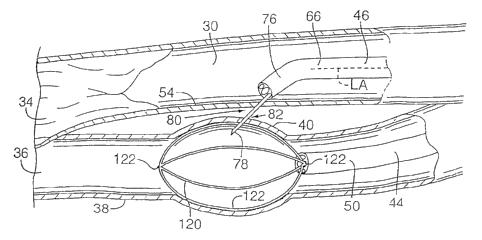
Figs. 13-15 show an alternative embodiment for venous-expansion
catheter 44, including a wire basket 120 deployable adjacent distal end 50 of
catheter
44. Wire basket 120 can be compressed within distal end 50 of catheter 44
while
catheter 44 is guided to the fistula site, and when deployed, the wire basket
expands
radially with sufficient force to extend outwardly wall 38 of vein 36 towards
contact
with artery wall 32. Wire basket is shown as formed of four limbs, but other
numbers
of liinbs may be used, e.g., six or eigllt. The maximum force of expansion for
any
particular wire basket 120 may be set by the nominal dimensions of the basket
and
may be adjusted by the physician during the operation, e.g., by adjusting the
extent to
which the basket is deployed beyond distal end 50. Wire basket 120 can dilate
the vein
typically about 3-mm to about 10-mm, or, if necessary, as much as about 15-mm.
Wire basket 120 may be made of a radiopaque material, or may include
one or more radiopaque markers 122 positioned to allow radiographic
determination
of the position and expansion of the basket, e.g., at the fore and aft ends of
the basket
CA 02413668 2003-01-03
WO 02/02163 PCT/US01/21560
and the midpoints of each limb. The physician can observe radiographically
basket
120 or markers 122 to judge the position and efficacy of the expansion of vein
36.
Wire basket 120 is typically coupled to a wire, such as wire 62 of Figs.
1-3 inserted through one of the lumens in venous catheter 44 and wire 62 is
5 controllable by the physician in position relative to catheter 44 to control
deployment
of basket 120. As with the embodiment shown in Figs. 1-3, arterial catheter 46
of
catheter apparatus 32 includes a distal end 66 that the physician inserts into
artery 30
and positions adjacent arterial fistula site 54. The physician creates
openings 80, 82 in
the artery and vein walls as for the previous embodiment, except that wire
basket 120
10 will maintain its shape and the expansion of the vein walls without concern
for
potential puncture and deflation of a balloon. Wire basket 120 may include one
or
more magnets, or other magnetically-attracted material cooperating with one or
more
magnets, or other magnetically-attracted material on arterial catheter 46,
needle 78 or
wire 88 to urge the basket and the catheter, needle, or wire toward one
another.
15 Figs. 16-19 show another embodiment of the present invention wherein
the radially expandable structure of venous catheter 44 includes two balloons
124, 126
longitudinally spaced along distal end 50 with an injection port 128 between
the
balloons. Balloons 124, 126 are shown inflated, in Fig. 16, creating an
isolated area
130 in the vein between the balloons and expanding outwardly vein wall 38
adjacent
fistula site 40. The balloons typically are inflated with a solution
containing a contrast,
and/or the catheter includes radiopaque markers, allowing the physician to
gauge the
position of the balloons before, during, and after inflation. As shown in Fig.
17, a
solution 132, also including a contrast, may be pumped into isolated area 130
through
injection port 128 under sufficient pressure to cause vein wall 38 further to
extend
outwardly toward contact with artery wall 32. The physician may check the
extension
of vein wall 38 by radiographically observing the contrast in solution 132.
The embodiment of Figs. 16-19 is similar to that of Figs. 1-3 for creating
openings 80, 82 in the artery and vein walls: the physician inserts arterial
catheter 46
into artery 30 and distal offset tip 76 is pointed at arterial fistula site
54. As shown in
CA 02413668 2003-01-03
WO 02/02163 PCT/US01/21560
16
Figs. 18 and 19 the tool for creating openings 80, 82 in the artery and vein
walls is
sharp-tipped wire 88. As wire 88 creates opening 82 in vein wa1138, vein 32
generally
maintains the expanded shape because the sharp-tipped wire enters into
isolated area
130, rather than either of balloons 124, 126. Balloons 124, 126 can then be
deflated
and withdrawn, and wire 88 further extended into vein 32, as shown in Fig. 19.
A
balloon catheter and/or a stent may be maneuvered through the openings, as
described
above for Figs. 5 and 11-12 respectively.
Figs. 20 and 21 show an alternative embodiment for providing the
inactive and active configurations, respectively, for needle 78. In this
embodiment,
needle 78 is hollow and terminates in a beveled, pointed tip 134, and is
typically
coupled to arterial catheter 46 in a fixed relative position beyond distal end
66 of
catheter 46. That is, needle 78 is not made inactive by retraction into distal
end 66 of
catheter 46. Instead, wire 74 terminates in a generally blunt distal end 136,
and to
provide the inactive configuration, as shown in Fig. 20, wire 74 is inserted
through
needle 78 to a position at least flush with needle tip 134 wherein tip 134
cannot causes
trauma to vessel walls. As shown in Fig. 21, the active configuration is
provided by
withdrawing wire 74 from needle tip 134, so that tip 134 can create the
desired
openings through the artery and vein walls as described above.
It is believed that the disclosure set forth above encoinpasses multiple
distinct inventions with independent utility. While each of these inventions
has been
disclosed in its preferred form, the specific embodiunents thereof as
disclosed and
illustrated herein are not to be considered in a limiting sense as numerous
variations
are possible. The subject matter of the inventions includes all novel and non-
obvious
combinations and subcombinations of the various elements, features, functions
and/or
properties disclosed herein. No single feature, function, element or property
of the
disclosed embodiments is essential to all of the disclosed inventions.
Similarly, where
the claims recite "a" or "a first" element or the equivalent thereof, such
claims should
be understood to include incorporation of one or more such elements, neither
requiring
nor excluding two or more such elements.
CA 02413668 2003-01-03
WO 02/02163 PCT/US01/21560
17
It is believed that the following claims particularly point out certain
combinations and subcombinations that are directed to one of the disclosed
'uiventions
and are novel and non-obvious. Inventions embodied in other combinations and
subcombinations of features, functions, elements and/or properties may be
claimed
through amendinent of the present claims or presentation of new claims in this
or a
related application. Such amended or new claims, whether they are directed to
a
different invention or directed to the same invention, whether different,
broader,
narrower or equal in scope to the original claims, are also included within
the subject
matter of the inventions of the present disclosure.