Sélection de la langue

Search

Sommaire du brevet 2419509 

Énoncé de désistement de responsabilité concernant l'information provenant de tiers

Une partie des informations de ce site Web a été fournie par des sources externes. Le gouvernement du Canada n'assume aucune responsabilité concernant la précision, l'actualité ou la fiabilité des informations fournies par les sources externes. Les utilisateurs qui désirent employer cette information devraient consulter directement la source des informations. Le contenu fourni par les sources externes n'est pas assujetti aux exigences sur les langues officielles, la protection des renseignements personnels et l'accessibilité.

Disponibilité de l'Abrégé et des Revendications

L'apparition de différences dans le texte et l'image des Revendications et de l'Abrégé dépend du moment auquel le document est publié. Les textes des Revendications et de l'Abrégé sont affichés :

  • lorsque la demande peut être examinée par le public;
  • lorsque le brevet est émis (délivrance).
(12) Demande de brevet: (11) CA 2419509
(54) Titre français: DISPOSITIF DE RINCAGE POUR CATHETER VASCULAIRE
(54) Titre anglais: APPARATUS FOR FLUSHING A VASCULAR CATHETER
Statut: Réputée abandonnée et au-delà du délai pour le rétablissement - en attente de la réponse à l’avis de communication rejetée
Données bibliographiques
(51) Classification internationale des brevets (CIB):
  • A61M 39/22 (2006.01)
(72) Inventeurs :
  • SCHWARTZ, ROBERT S. (Etats-Unis d'Amérique)
  • HOLMES, DAVID R. (Etats-Unis d'Amérique)
  • BERRY, DAVID (Etats-Unis d'Amérique)
  • ELLIS, DONALD G. (Etats-Unis d'Amérique)
(73) Titulaires :
  • MAYO FOUNDATION FOR MEDICAL EDUCATION AND RESEARCH
(71) Demandeurs :
  • MAYO FOUNDATION FOR MEDICAL EDUCATION AND RESEARCH (Etats-Unis d'Amérique)
(74) Agent: SMART & BIGGAR LP
(74) Co-agent:
(45) Délivré:
(86) Date de dépôt PCT: 2000-08-01
(87) Mise à la disponibilité du public: 2002-02-07
Licence disponible: S.O.
Cédé au domaine public: S.O.
(25) Langue des documents déposés: Anglais

Traité de coopération en matière de brevets (PCT): Oui
(86) Numéro de la demande PCT: PCT/US2000/040534
(87) Numéro de publication internationale PCT: US2000040534
(85) Entrée nationale: 2003-01-29

(30) Données de priorité de la demande: S.O.

Abrégés

Abrégé français

Cette invention concerne un dispositif de rinçage pour cathéter vasculaire. Des passages d'entrée et de sortie partant des orifices d'entrée et de sortie, respectivement, peuvent être mis sélectivement connectés l'un à l'autre via un élément à commande manuelle qui coopère avec un élément d'obturation et qui est rappelé à force en position fermée. Sont inclus mécanismes de rinçage périodiques ou permanents.


Abrégé anglais


An apparatus for flushing a vascular catheter. Inlet and outlet passages
extending from inlet and outlet ports, respectively, are selectably in
communication with one another via a manually operable member cooperating with
a sealing member and biased toward a closed position. Mechanisms for
continuously and periodically flushing the catheter are incorporated.

Revendications

Note : Les revendications sont présentées dans la langue officielle dans laquelle elles ont été soumises.


WE CLAIM:
An apparatus for flushing a vascular catheter, comprising:
(a) a housing having an inlet port for connection to a flushing liquid
source and an outlet port for communication with the vascular catheter;
(b) inlet and outlet passages in communication with said inlet and outlet
ports, respectively, and selectably in communication with one another;
(c) a manually operable member biased toward a closed position and
movable to an open position; and
(d) a sealing member cooperating with said manually operable member,
wherein in said closed position said inlet and outlet passages are sealed from
one
another by said sealing member, and in said open position said inlet and
outlet
passages are in communication with one another;
(e) said sealing member constructed and arranged such that a movement
of said sealing member toward a sealed position is substantially slowed,
thereby
flushing the vascular catheter for a period of time after said manually
operable
member has been moved to said open position.
2. An apparatus for flushing a vascular catheter according to claim 1, wherein
said manually operable member is a button movable between extended and
depressed positions corresponding to said closed and open positions
respectively.
3. An apparatus for flushing a vascular catheter according to claim 2, wherein
said sealing member is a plunger having a sealing gasket around it, said
plunger
being rigidly connected to said button.
4. An apparatus for flushing a vascular catheter according to claim 1, wherein
said manually operable member is biased toward said closed position by a
spring.
5. An apparatus for flushing a vascular catheter according to claim 1, wherein
said movement of said sealing member toward said sealed position is slowed by
means for creating a temporary differential pressure pulling said sealing
member
away from said sealed position.
6. An apparatus for flushing a vascular catheter according to claim 5, wherein
said pressure differential creating means comprise a sealed chamber having an
inlet
into which fluid slowly flows.

7. An apparatus for flushing a vascular catheter according to claim 6, wherein
said apparatus is constructed and arranged such that said fluid is flushing
liquid
received from said inlet port.
8. An apparatus for flushing a vascular catheter according to claim 6, further
including means for expelling fluid from said chamber when said sealing member
is
moved into said chamber.
9. An apparatus for flushing a vascular catheter according to claim 1, further
including means for continuously flushing the vascular catheter by providing a
relatively slow rate of flow of flushing liquid from said inlet port to said
outlet port.
10. An apparatus for flushing a vascular catheter according to claim 9,
wherein
said continuously flushing means are also employed to slow a movement of said
sealing member to a sealed position.
11. An apparatus for flushing a vascular catheter, comprising:
(a) a housing having an inlet port for connection to a flushing liquid
source and an outlet port for communication with the vascular catheter;
(b) means for continuously flushing the vascular catheter by providing a
relatively slow rate of flow of flushing liquid from said inlet port to said
outlet port;
(c) means for periodically flushing the vascular catheter by bypassing
said continuously flushing means to provide a relatively high rate of flow of
flushing
liquid from said inlet port to said outlet port; and
(d) said periodic flushing means including a manually operable member
constructed and arranged such that, after being moved to a bypass position, a
movement of said member toward a closed position is substantially slowed,
thereby
continuing to flush the vascular catheter at a relatively high rate for a
period of time
after said manually operable member has been moved to said bypass position.
12. An apparatus for flushing a vascular catheter according to claim 11,
wherein
said continuous flushing means comprise a capillary tube providing flushing
fluid at
a rate of about between 0.10 and 10.0 cubic centimeters per minute.
13. An apparatus for flushing a vascular catheter according to claim 11,
wherein
said manually operable member is a button biased toward said closed position
by a
compression spring.
6

14. An apparatus for flushing a vascular catheter according to claim 11,
wherein
said movement of said manually operable member toward said closed position is
slowed by means for creating a temporary pressure differential pulling said
manually
operable member away from said closed position.
15. An apparatus for flushing a vascular catheter according to claim 14,
wherein
said pressure differential creating means comprise a sealed chamber having an
inlet
into which fluid slowly flows.
16. An apparatus for flushing a vascular catheter according to claim 15,
wherein
said pressure differential creating means comprise at least a portion of said
continuously flushing means.
17. An apparatus for flushing a vascular catheter according to claim 11,
wherein
said apparatus is constructed and arranged such that said period of time is at
least 5
seconds.
18. An apparatus for flushing a vascular catheter according to claim 1,
wherein
said apparatus is constructed and arranged such that said period of time is at
least 5
seconds.
7

Description

Note : Les descriptions sont présentées dans la langue officielle dans laquelle elles ont été soumises.

CA 02419509 2003-O1-29
WO 02/09804 PCT/US00/40534
APPARATUS FOR FLUSHING A VASCULAR CATHETER
Field of the Invention
This invention relates generally to devices used in vascular catheter
procedures, and more particularly to devices for flushing a catheter during
such
procedures. 5
Background of the Invention
When performing diagnostic, therapeutic or interventional vascular
procedures involving a catheter, it is necessary to flush the catheter
(typically with
saline) in order to prevent blood clots from forming. The device most commonly
used today is a manifold with a number of manually operated stopcock valves.
Periodically the physician or technician must manually open or close one or
more
stopcocks for a period of time so that saline from a high pressure source can
flush
the catheter. After a satisfactory amount of flushing has been done, the
stopcocks
are again manually moved back to their original position, and the surgeon then
resumes performing the procedure.
There are a number of shortcomings with the existing manifold. One
is that the physician is "hands off' from performing the procedure for a long
period
of time (20 seconds or more per flush), which time could instead be used to
perform
the procedure on the patient. Having to manually flush also breaks the
continuity of
the procedure, which can be distracting. It also requires that the operator
(if not the
physician) is at all times sterile. Another shortcoming is that flushing must
be done
fairly often. During each flush, blood pressure readings are interrupted,
which is
undesirable. Each additional flush is also another interruption, potential
distraction
and further delay of the procedure.
What has been needed is an apparatus for flushing a vascular catheter
which automatically closes and which provides a relatively slow continuous
flush of
the catheter.
Summary of the Invention
According to the present invention, an apparatus for flushing a
vascular catheter is provided. The inventions can be used in a variety of
diagnostic,
therapeutic and interventional procedures involving a vascular catheter.
In one aspect of the invention, the apparatus comprises a housing
having an inlet port for connection to a flushing liquid source, and an outlet
port for
communication with the vascular catheter. Inlet and outlet passages are in
communication with the inlet and outlet ports, respectively, and are also
selectively

CA 02419509 2003-O1-29
WO 02/09804 PCT/US00/40534
in communication with one another. A manually operable member is biased toward
a closed position and moveable to an open position. A sealing member
cooperates
with the manually operable member such that, in the closed position, the inlet
and
outlet passages are sealed from one another by the sealing member; in the open
position, the inlet and outlet passages are in communication with one another.
Thus,
when the manually operable member is released, it automatically returns to a
closed
position. In a preferred version, the sealing member is slowed toward a sealed
position, thereby flushing the catheter for a period of time after the
manually
operable member has been moved to the open position.
In another aspect of the invention, the apparatus comprises a housing
having an inlet port for connection to a flushing liquid source and an outlet
port for
communication with the vascular catheter. Mechanisms for continuously and
periodically flushing are provided. The continuously flushing mechanism
provides a
relatively slow rate of flow of flushing fluid from the inlet port to the
outlet port.
The periodically flushing mechanism bypasses the continuously flushing
mechanism
to provide a relatively high rate of flow of flushing liquid from the inlet
port to the
outlet port.
These and other advantages and features of novelty which
characterize the invention are pointed out with particularity in the claims
annexed
hereto. However, for a better understanding of the invention and its
advantages,
reference should be made to the drawing which forms a further part hereof, and
to
the accompanying descriptive matter in which there is illustrated and
described a
preferred embodiment of the invention.
Brief Description of the Drawing
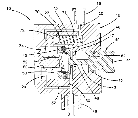
Figure 1 is a cross-sectional view of an apparatus for flushing a
vascular catheter according to the present invention.
Detailed Description of the Preferred Embodiment
Referring now to the drawing, an embodiment of the apparatus of the
present invention for flushing a vascular catheter is shown in figure 1.
Apparatus 10 comprises housing 1 S including inlet 16 and outlet 18
ports. Inlet port 16 is for connection to a high pressure liquid (typically
saline)
flushing source as is commonly used. Outlet port 18 is for communication with
the
vascular catheter, typically through a hemostasis valve.
Apparatus 10 is constructed so that it will automatically return to a
closed position after its manually operable member 40 is moved to an open
position.
Member 40 includes button 41, stem 43, and sealing member 45 configured as a
2

CA 02419509 2003-O1-29
WO 02/09804 PCT/US00/40534
piston, the latter two constituting a plunger. Inlet 20 and outlet 30 passages
provide
communication between inlet 16 and outlet 18 ports, respectively, and bypass
chamber 62. O-rings 42, 47 on button 41 and stem 43 seal chamber 62. When
button 41 is depressed, O-ring 47 moves away from seating surface 48, thereby
causing flushing liquid to pass from inlet passage 20, through bypass chamber
62
and out outlet port 18 to the catheter. Manually operable member 40 and
sealing
member 45 are biased toward a closed position (shown) by compression spring 52
on plunger stop 50. Plunger stop 50 defines the end of the open position by
sealing
member 45 abutting against it.
It will be understood that this arrangement could be varied in a
number of ways within the principles of the invention. For example, a lever
could
be employed instead of a button and plunger. The manually operable member and
sealing member also need not be an integral part. A variety of springs (or
spring
means) could also be employed, and the spring could act on either the operable
member or the sealing member.
Apparatus 10 also provides a mechanism by which sealing member
45 is slowed to a closed position so that high pressure flushing fluid
continues to
flush the catheter after operable member 40 is released. This is accomplished
by
capillaries 24, 34 and timing chamber 60. Chamber 60 is sealed by O-ring 46 on
sealing member 45. When sealing member 45 begins to move out of chamber 60 (to
the right in figure), low pressure on the bottom (left in figure) side of
sealing
member 45 keeps manually operable members 40 from moving back to an extended
position. Member 40 gradually moves to the extended position as saline is
drawn
into timing chamber 60 through capillaries 24, 34, which receive flushing
liquid
from inlet 20 and outlet 30 passages via capillary inlet 22 and outlet 32
passages. As
flushing liquid from capillaries 24, 34 slowly fills timing chamber 60, after
a period
of time sealing and operable member 40 returns to the extended position, and O-
ring
47 closes bypass chamber 62, thereby ending the bypass of high rate liquid
flush.
The preferred amount of bypass time is preferably about 20 seconds.
The design parameters of the various parts involved could be varied to achieve
this.
In the preferred version, sealing member 45 has a stroke length of 0.29 inches
and a
diameter of 0.75 inches. Capillaries 24, 34 are 0.30 inches long and have an
inside
diameter of 0.0060 inches, resulting in a conductance of approximately 0.04
cubic
inches/minute/psi. The mean effective force of spring 52 is about 4 pounds.
It will be understood that a variety of other mechanisms could be
employed to slow the movement of the sealing member to the closed position.
For
example, air from the atmosphere could be drawn through a pin hole into a
timing

CA 02419509 2003-O1-29
WO 02/09804 PCT/US00/40534
chamber to provide the necessary resistance. Other approaches using air,
liquid ,
another spring means or other mechanisms could also be employed.
Check valve 70 is provided to expel liquid from timing chamber 60
when button 41 is depressed. Check valve 70 includes spring 73 biasing ball 72
to a
closed position (shown). When button 41 is depressed, capillaries 24, 34
resist flow
through them so that ball 72 unseats and liquid flows from timing chamber 60,
through passage 71 and out inlet port 16. A variety of other arrangements
could be
employed to similarly expel liquid or air from a timing chamber.
Apparatus also provides a relatively slow rate continuous flush of the
catheter. This is accomplished by capillaries 24, 34 creating a slow flow from
inlet
port 16 to outlet port 18 via timing chamber 60. The rate of flow is a slow
drip, on
the order of 1.0 ml./min. (at 300 mm. Hg pressure drop), resulting in a
conductance
of 0.010 cubic inches/minute/psi from the above capillary specifications.
In this way, capillaries 24, 34 serve dual roles. They provide for a
slow rate continuous flush, and they also act as the resistance mechanism for
slowing
the movement of operable member 40 to a bypass closed position.
It will be understood that the apparatus could be modified in a
number of ways to provide both continuous flushing and periodic flushing that
bypasses the continuous flushing mechanism. A variety of mechanical and
electronic means, or a combination thereof, could be employed to achieve this
end.
Periodic flushing could also be done automatically instead of manually.
It should be understood that the present invention is not limited to the
preferred embodiment discussed above, which is illustrative only. Changes may
be
made in detail, especially in matters of the type, arrangement, shape and size
of
components within the principles of the invention, to the full extent
indicated by the
broad general meanings of the terms in which the appended claims are
expressed.
4

Dessin représentatif
Une figure unique qui représente un dessin illustrant l'invention.
États administratifs

2024-08-01 : Dans le cadre de la transition vers les Brevets de nouvelle génération (BNG), la base de données sur les brevets canadiens (BDBC) contient désormais un Historique d'événement plus détaillé, qui reproduit le Journal des événements de notre nouvelle solution interne.

Veuillez noter que les événements débutant par « Inactive : » se réfèrent à des événements qui ne sont plus utilisés dans notre nouvelle solution interne.

Pour une meilleure compréhension de l'état de la demande ou brevet qui figure sur cette page, la rubrique Mise en garde , et les descriptions de Brevet , Historique d'événement , Taxes périodiques et Historique des paiements devraient être consultées.

Historique d'événement

Description Date
Demande non rétablie avant l'échéance 2006-08-01
Inactive : Morte - RE jamais faite 2006-08-01
Réputée abandonnée - omission de répondre à un avis sur les taxes pour le maintien en état 2006-08-01
Inactive : Abandon.-RE+surtaxe impayées-Corr envoyée 2005-08-01
Lettre envoyée 2004-08-19
Inactive : Supprimer l'abandon 2004-08-10
Inactive : Abandon. - Aucune rép. à lettre officielle 2004-06-15
Inactive : Correspondance - Transfert 2004-05-14
Inactive : Renseignement demandé pour transfert 2004-03-15
Inactive : Transfert individuel 2004-01-28
Inactive : Lettre de courtoisie - Preuve 2003-04-29
Inactive : Page couverture publiée 2003-04-24
Inactive : Notice - Entrée phase nat. - Pas de RE 2003-04-22
Demande reçue - PCT 2003-03-18
Exigences pour l'entrée dans la phase nationale - jugée conforme 2003-01-29
Demande publiée (accessible au public) 2002-02-07

Historique d'abandonnement

Date d'abandonnement Raison Date de rétablissement
2006-08-01

Taxes périodiques

Le dernier paiement a été reçu le 2005-06-20

Avis : Si le paiement en totalité n'a pas été reçu au plus tard à la date indiquée, une taxe supplémentaire peut être imposée, soit une des taxes suivantes :

  • taxe de rétablissement ;
  • taxe pour paiement en souffrance ; ou
  • taxe additionnelle pour le renversement d'une péremption réputée.

Les taxes sur les brevets sont ajustées au 1er janvier de chaque année. Les montants ci-dessus sont les montants actuels s'ils sont reçus au plus tard le 31 décembre de l'année en cours.
Veuillez vous référer à la page web des taxes sur les brevets de l'OPIC pour voir tous les montants actuels des taxes.

Historique des taxes

Type de taxes Anniversaire Échéance Date payée
TM (demande, 2e anniv.) - générale 02 2002-08-01 2003-01-29
Taxe nationale de base - générale 2003-01-29
TM (demande, 3e anniv.) - générale 03 2003-08-01 2003-07-16
Enregistrement d'un document 2004-01-28
TM (demande, 4e anniv.) - générale 04 2004-08-02 2004-06-25
TM (demande, 5e anniv.) - générale 05 2005-08-01 2005-06-20
Titulaires au dossier

Les titulaires actuels et antérieures au dossier sont affichés en ordre alphabétique.

Titulaires actuels au dossier
MAYO FOUNDATION FOR MEDICAL EDUCATION AND RESEARCH
Titulaires antérieures au dossier
DAVID BERRY
DAVID R. HOLMES
DONALD G. ELLIS
ROBERT S. SCHWARTZ
Les propriétaires antérieurs qui ne figurent pas dans la liste des « Propriétaires au dossier » apparaîtront dans d'autres documents au dossier.
Documents

Pour visionner les fichiers sélectionnés, entrer le code reCAPTCHA :


Pour visualiser une image, cliquer sur un lien dans la colonne description du document. Pour télécharger l'image (les images), cliquer l'une ou plusieurs cases à cocher dans la première colonne et ensuite cliquer sur le bouton "Télécharger sélection en format PDF (archive Zip)" ou le bouton "Télécharger sélection (en un fichier PDF fusionné)".

Liste des documents de brevet publiés et non publiés sur la BDBC .

Si vous avez des difficultés à accéder au contenu, veuillez communiquer avec le Centre de services à la clientèle au 1-866-997-1936, ou envoyer un courriel au Centre de service à la clientèle de l'OPIC.


Description du
Document 
Date
(aaaa-mm-jj) 
Nombre de pages   Taille de l'image (Ko) 
Description 2003-01-28 4 221
Dessins 2003-01-28 1 25
Dessin représentatif 2003-01-28 1 24
Revendications 2003-01-28 3 123
Abrégé 2003-01-28 1 66
Avis d'entree dans la phase nationale 2003-04-21 1 189
Demande de preuve ou de transfert manquant 2004-02-01 1 103
Courtoisie - Certificat d'enregistrement (document(s) connexe(s)) 2004-08-18 1 105
Rappel - requête d'examen 2005-04-03 1 117
Courtoisie - Lettre d'abandon (requête d'examen) 2005-10-10 1 167
Courtoisie - Lettre d'abandon (taxe de maintien en état) 2006-09-25 1 175
PCT 2003-01-28 6 206
Correspondance 2003-04-21 1 25
Taxes 2003-07-15 1 32
Correspondance 2004-03-14 1 21
Taxes 2004-06-24 1 31
Taxes 2005-06-19 1 28