Note : Les descriptions sont présentées dans la langue officielle dans laquelle elles ont été soumises.
CA 02430494 2003-05-28
WO 02/052314 PCT/USO1/43405
SIDE-ILLUMINATION TYPE OPTICAL FIBER
Technical Field
The present invention relates to a side light type optical fiber.
Particularly, it
relates to a side light type optical fiber, which emits light introduced from
at least one end
of a core in a longitudinal direction through a cladding surrounding the core.
Background Art
As is already known to the art, a discharge tube, like a fluorescent tube,
emits
visible light having a specified wave length region, and is used for
illumination purposes.
When the discharge tube is a neon tube, the tube is often employed for
advertisement or
ornamental use in the form of neon signs. The discharge tube emits light when
applying
an electric discharge. It also emits heat together with light. The heat and
lealcage of
electricity should be considered when using the discharge tube. The discharge
tube, as the
result, can not be used for illuminating or displaying in water.
In order to realize the illumination or display in water, an illuminating
device in
which its light source is placed separate from a place to be illuminated or
displayed has
been recently suggested. The illuminating device comprises a light source
which is
separately placed from an illuminating or displaying place, and an optical
fiber for
illumination or display, placed near or at the illuminating or displaying
place. The optical
fiber generally includes a core at a center portion, in which a light
introduced from one
end of the fiber is transmitted to the other end, and a cladding having lower
refractive
index than the core, disposed around the core.
Among the optical fibers, there has been known a side light type optical fiber
which can emit light from its side portion. The side light type optical fiber
is explained by
reference with Fig. 4. The optical fiber 20 is flexible and includes a core 21
formed from
acrylic resin or the like, and a cladding 22 formed from
Polytetrafluoroethylene available
commercially under the name Teflon TM from E.I. Dupont de Nemours and Company
and
the like, as disclosed in U.S. Patent 4,422,719. The cladding 22 uniformly
contains light
diffusive particles, such as metal oxide particles (e.g. titanium dioxide
particles) in an
amount of 2 to 10 % by weight. In addition, Japanese Kolcai Publication Hei-10
(1998) -
CA 02430494 2003-05-28
WO 02/052314 PCT/USO1/43405
148725 discloses an optical fiber which is obtained by co-extruding a melted
fluoropolymer containing 50 to 4,000 ppm of at least one light diffusive
additive with a
crosslinlcable resin mixture for core. WO 98/08024 also discloses an optical
fiber which is
formed by melt-casting a semi-transparent cladding material containing white
or another
color pigment on a surface of a core. The optical fibers mentioned above can
emit a light
through the cladding, when light is introduced from one or both ends of the
fiber to
transmit within the fiber.
It is also known that the cladding layer contains another layer light
diffusive layer.
For example, Japanese Kokai 2000-131530 discloses that a cladding layer is
divided into
two layers, one of which contains light diffusive particles to constitute a
light diffusive
layer and the other is a transparent layer not containing light diffusive
particles, formed on
the light diffusive layer. The two layers are integrally formed by co-
extrusion. In this
technique, the light diffusive layer is directly contacted with the core.
In the construction obtained in Japanese Kolcai 2000-131530, a lateral
luminance
of the fiber is effectively enhanced in especially a portion near the light
source, but the
luminance would attenuate as parting from the light source. This is because
the greater the
distance from the light source, the more the luminance attenuates.
Accordingly, the
optical fiber disclosed in Japanese Kokai 2000-131530 is not effectively used
for an
illumination device having a long fiber length of 10 m or more, when the fiber
is used as a
light illmninant.
Summary of Invention
The present invention, as attaining the above-mentioned object, provides a
side
light type optical fiber (referred sometimes to as merely "optical fiber"),
which comprises
a core and a cladding disposed around the core, the cladding is including a
transparent first
layer contacting the core, and a light diffusive second layer formed around
the first layer,
the both layers being integrally molded. In the present invention, the first
layer preferably
has a thickness of 50 to 300 ~,m. The core preferably has a diameter of 5 to
30 mm. It is
also preferred that the cladding has a dual layer structure formed by a co-
extrusion method
of two materials for the first and second layers.
2
CA 02430494 2003-05-28
WO 02/052314 PCT/USO1/43405
Brief Description of the Drawings
Fig. 1 A schematic cross sectional view of the side light type optical fiber
of the
present invention.
Fig. 2 A graph showing a result of test of side light luminance of Examples
and
Comparative Examples. This figure shows a change of luminance against distance
from a
light source.
Fig. 3 A graph showing a result of test of side light huninance of Examples
and
Comparative Examples. This figure shows a change of luminance against a
measuring
angle at 2 mm away from a light source.
Fig. 4 A schematic cross sectional view of the side light type optical fiber
of a
prior art.
Detailed Description
The long side light type optical fiber with 10 m or more length, can also be
obtained by covering an optical fiber having a transparent single-layer
cladding on the
core with a light diffusive semi-transparent resin layer so as to enhance
uniformity of
luminance over a longitudinal direction and to emit light brightly. This is
because an
optical fiber including a core and a transparent single-layer cladding
covering on the core
can transmit light from one end to the other end in a longitudinal direction
without leaking
light from a surface of the cladding, that is, side face. This is because
light introduced in
the fiber is effectively transmitted by total internal reflection at an
interface between the
cladding having a relatively lower refractive index and the core having a
relatively higher
refractive index.
On the other hand, in case where the core has a relatively larger diameter,
for
example more than 3 mm, the light in the fiber lealcs slightly out from the
side face to
illuminate a little over the longitudinal dimension, even if the cladding does
not contain
light diffusive particles. The larger the diameter of the core, the more the
phenomenon
occurs, because more light which does not meet conditions for total internal
reflection and
reaches the interface between core and cladding is present. In addition, an
adhesion
between the cladding and the core microscopically is not uniform in some
portions,
although it visibly has very good transparency. The portions having
nonuniformities
become illuminating points.
3
CA 02430494 2003-05-28
WO 02/052314 PCT/USO1/43405
The leaking light has generally a relatively low angle to a direction parallel
to the
cladding side face and largely contains components to emit out from the
cladding side
face. Accordingly, the optical fiber having a semi-transparent light-diffusive
resin layer
on the cladding has sufficient uniformity of luminance over the longitudinal
direction, but
is poor in luminance strength because of the leakage of light, so that the
fiber is not used
for a long light illuminant, like a neon tube.
This necessitates that the light-diffusive layer be more closely adhered to
the
cladding surface to reduce the escapes of light having a relatively low angle
to a direction
parallel to the cladding side face and to increase the escape of light having
a relative high
mgle to the direction parallel to the cladding side face.
In order to closely adhere a light-diffusive layer on the cladding surface,
some
methods are already known. For example, there is a method for covering an
electric wire
with resin, which comprises cool-solidifying a resin melted mixture of a
transparent
polymer and white inorganic powder dispersed therein onto the surface of the
cladding
layer of the optical fiber. Another method comprises preparing a light-
diffusive resin tube
and inserting an optical fiber into the light-diffusive resin tube.
However, the above-mentioned methods both include an additional step for
covering the light-diffusive layer on the cladding surface to result in
increase of cost for
production.
In addition, since the light-diffusive layer is separately formed and covered
on the
surface of the cladding, it is difficult to enhance an adhesion between the
cladding and the
light-diffusive layer. This often creates layer separation between the light-
diffusive layer
and the cladding because of a bending operation of the fiber, a change of
temperature and
the like. Once the layer separation occurs, the luminance of the separated
portion reduces
and generates some difference on luminance over the fiber. The fiber thus does
not
operate well as a light illuminant for illumination.
The present inventors have studied more about occurrence of layer separation
between the fiber and the light-diffusive layer and have found that the
occurrence of layer
separation is observed more often when the optical fiber has a larger core
diameter,
especially 5 mm or more core diameter. The reasons why the tendency exists
will be
described below.
In case of glass fiber, the fiber is twisted to absorb bending deformation, to
result
4
CA 02430494 2003-05-28
WO 02/052314 PCT/USO1/43405
in the glass fiber bending without breakage. On the other hand, if a glass
article has a
larger diameter than the fiber, for example a glass rod, it can not bend at
all and therefore
if too much bending force is applied on the rod it will brealc. It is
generally true that a rod
shape article having a large diameter does not twist at all against bending
operation and
does not absorb the bending deformation. Accordingly, the layer separation
between the
cladding and the light-diffusive layer operates as the same as the glass rod
and occurs
often when the optical fiber has a lager diameter.
The present invention will be explained referring with representative
embodiments.
In the drawings attached to the present application, the same numbers show
same elements
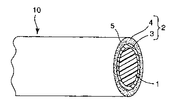
or equivalent elements. In Fig. 1, an optical fiber 10 is indicated as one
embodiment of
the present invention. The optical fiber 10 has a core 1 at its center portion
and a cladding
2 surrounding the core 1.
The core is generally formed from polymer. The core formed from polymer can be
obtained by polymerizing a polymerizable material. The core can accept light
without loss
from a light source from one or both exposed ends into the core. The core has
a sufficient
light transmittance and transmits light from one end to the other end.
The core has a light transmittance of not less than 80 %. By the term "light
transmittance" herein is meant a value determined by a spectrophotometer using
a light
having a wavelength of 550 rim. The polymer for the core generally has a
refractive index
of 1.4 to 1.7.
The core preferably is a solid core formed from flexible polymer. The flexible
polymer can preferably be acrylic polymer, ethylene-vinyl acetate copolymer,
vinyl
acetate-vinyl chloride copolymer or a mixture thereof. The polymer of the core
can
preferably be crosslinlced in order to enhance water resistance.
The polymerizable material for the core can be an acrylic monomer mixture. The
acrylic monomer mixture for the core contains (1) a polymerizable acrylic
monomer not
having a hydroxyl group in a molecule and (2) a polymerizable hydroxyl-
containing
acrylic monomer. The term "acrylic monomer" used herein include either a
monomer
having an acrylic group or a monomer having a methacrylic group or both.
Preferred is a
methacrylate, i.e. methacrylic ester. The methacrylate can easily control a
core Tg to a
suitable range and can effectively enhance properties in water resistance,
light
transmittance and the lilce. The polymerizable material for the core can also
be a
5
CA 02430494 2003-05-28
WO 02/052314 PCT/USO1/43405
(meth)acrylic oligomer formed by reacting at least two monomers, as long as
the technical
effects of the present invention does not deteriorate. A crosslinlcable
monomer having two
or more functional groups can also be used in addition to the mono-functional
monomer.
Examples of the acrylic monomers not having an hydroxyl group are a
methacrylate, such as methyl methacrylate, ethyl methacrylate, n-butyl
methacrylate, 2-
ethylhexyl methacrylate, isobutyl methacrylate, t-butyl methacrylate, lauryl
methacrylate,
dodecyl methacrylate and stearyl methacrylate. An acrylate not having hydroxyl
group
can be used in addition to the methacrylate and include methyl acrylate, ethyl
acrylate, n-
butyl acrylate, 2-ethylhexyl acrylate, isoamyl acrylate, lauryl acrylate,
stearyl acrylate,
isooctyl acrylate or the like. An unsaturated acid, such as acrylic acid or
methacrylic acid
can also be used as the monomer.
Examples of the hydroxyl-containing acrylic monomers are 2-hydroxyethyl
methacrylate, 2-hydroxyethyl acrylate, 2-hydroxypropyl methacrylate, 2-
hydroxypropyl
acrylate, 3-hydroxypropyl methacrylate, 3-hydroxypropyl acrylate,
diethyleneglycol
monomethacrylate, diethyleneglycol monoacrylate, triethyleneglycol
monomethacrylate,
triethyleneglycol monoacrylate and the like.
Examples of the crosslinlcing agents to crosslinlc the core polymer are
polyfunctional monomers, such as dially phtharate, triethyleneglycol
di(meth)acrylate,
diethyleneglycol bisallylcarbonate and the like.
Preferred examples of the acrylic monomer mixtures for the present invention
include:
(a) a mixture of 2-hydroxyethyl methacrylate, methyl methacrylate, n-butyl
methacrylate and triethyleneglycol di(meth)acrylate;
(b) a mixture of 2-hydroxyethyl methacrylate, n-butyl methacrylate and
triethyleneglycol di(meth)acrylate; and
(c) a mixture of 2-hydroxyethyl methacrylate, n-butyl methacrylate, 2-
ethylehexyl
methacrylate and triethyleneglycol di(meth)acrylate; and the like.
In case where the core polymer is crosslinlced by using a crosslinlcing agent,
an
amount of the crosslinlcing agent can preferably be 0.01 to 5.0 % by weight,
more
preferably 0.1 to 4.5 % by weight based on a total weight of the polymerizable
material.
The core may also contain an additive as long as the core does not deteriorate
its
properties. Examples of the additives are plasticizer, surfactant, colorant,
stabilizer for
6
CA 02430494 2003-05-28
WO 02/052314 PCT/USO1/43405
heat, oxidation or ultraviolet light, and the lilce.
Any ingredient of the polymerizable material for the core can be varied so as
to
satisfy properties, such as softness, weather resistance, coloring resistance
and water
resistance. A length of the core may generally be 50 to 100 m, but is not
limited thereto.
For exhibiting the technical effects of the present invention, it is preferred
that the core has
a length of 10 m or more, more preferably 15 m or more. The core generally has
a cross
section of about circle or ellipse in a direction of diameter, but does not
limit thereto.
The core generally has a diameter of 3 to 30 mm. Diameters of less than the
lower
diameter generally do not fit an application to illumination, because an area
of
illuminating is too thin and small for observers to see the illumination. On
the other hand,
diameters of more than larger limitation would significantly have attenuation
of lmninance
in a longitudinal direction and not enhance uniformity of luminance. In
addition, the
larger diameters reduce flexibility of the optical fiber and therefore do not
form into an
illumination apparatus containing the fiber having a desired shape. It is
therefore
preferred for showing good performance as an illuminant that the core has a
diameter of 6
to 27 mm, more suitably of 7 to 20 mm.
The cladding 2, as explained above, integrally molds both the first layer 3
and the
second layer 4 together. Preferably, the cladding 2 can be formed by a co-
extrusion
method, in which two or more layers for forming the cladding are melt-extruded
together
to form layer and cooled to solidify. The method effectively enhances an
adhesion
between the layers and does not increase number of steps for forming the
cladding. The
cladding of the present invention therefore can be produced as the same as a
conventional
cladding having a single layer with the exception that the cladding has plural
layers.
Materials for forming each cladding layer axe not limited, but generally
include a
polymer, such as tetrafluoroetylene-hexafluoropropylene copolymer (FEP),
tetrafluoroethylene-hexafluoropropylene-vinylidene fluoride copolymer,
trifluroethyle-
vinylidene fluoride copolymer, polymethylpentene, ethylene-vinyl acetate
copolymer,
vinyl acetate-vinyl chloride copolymer or the like. It is noted that the first
layer contacting
the core of the cladding has lower refractive index than the core.
The cladding may contain some additive as long as the addition does not
deteriorate the performance of the present invention. Examples of the
additives are
plasticizer, sufactant, curing agent, filler (e.g. white pigment), colorant
(e.g. dyestuff),
7
CA 02430494 2003-05-28
WO 02/052314 PCT/USO1/43405
stabilizer and the lilce.
The second layer being light diffusive property can generally be formed from a
material containing fluorine-containing polymer and light diffusive particles
dispersed in
the fluorine-containing polymer. An amount of the light diffusive particles is
generally
within the range of 0.01 to 50 % by weight, preferably 0.1 to 45 % by weight,
more
preferably 1 to 40 % by weight based on a total weight of the second layer.
Amounts of
less than the lower limitation may not have sufficient luminance (e.g. 100
candera/m2 or
more for wlute illuminant) for an illuminant like neon signs. Amounts of more
than 50
by weight may not emit light having enough luminance throughout a longitudinal
direction.
The light diffusive particles can generally be glass beads or beads obtained
from
another material, and inorganic particles, such as titanium dioxide or silicon
dioxide.
Concrete examples of the particles are white inorganic particles having a
refractive index
of 1.5 to 3Ø Preferred examples of the white inorganic particles are barium
sulfate
(refractive index =1.5), magnesia (refractive index = 1.8) and titania
(titanium dioxide;
refractive index = 2.6.
The light diffusive particles can be other ones as long as they do not
deteriorate the
techW cal effects of the present invention. In addition to the light diffusive
particles, a
colorant, such as fluorescent dye, can also be contained in the cladding layer
to change
white light introduced into the core to colored light and to emit it.
A transparency of the cladding first layer can be shown as light transmittance
and
is preferably more than 60 %, more preferably more than 70 %, most preferably
more than
90 %. If the cladding first layer has too small light transmittance, the
illuminant of the
fiber would reduce.
The cladding first layer preferably has a thiclcness of 50 to 300 Vim, more
preferably 70 to 280 ~,m, most preferably 100 to 250 Vim. It the cladding
first layer has
too small thickness, the attenuation of luminance would be significant over in
a
longitudinal direction and does not enhance uniformity of luminance in the
longitudinal
direction. In case where the core has a diameter of 5 mm or more, it is
preferred that the
cladding first layer should be as thick as possible for enhancing the
uniformity of
luminance. If the cladding first layer is too thick, a luminance at portions
away from the
light-introduced point would reduce and the uniformity of luminance does not
keep so far.
8
CA 02430494 2003-05-28
WO 02/052314 PCT/USO1/43405
In either case, the optical fiber is not suitable for an illuminant.for
illumination.
A thickness of the second layer of the cladding is not specifically limited
and can
be selected such a range as not to make the cladding opaque. It is preferred
that the
second layer has a thickness of more than 10 ~.m and the cladding totally has
a thickness
of not more than 2 mm.
The optical fiber of the present invention is produced by preparing a tube
type
cladding having a desired length and filling a polymerizable material into the
tube type
cladding, followed by polymerizing the material to form a polymerized core and
a
cladding covering the core. Detailed explanation of production is explained
hereinafter.
First of all, a cladding (i.e. cladding tube) is prepared. The cladding is
generally
obtained by a co-extrusion method to form a cladding tube having desired
thiclmess,
diameter and length. The cladding produced above is wound on a feed roll. The
cladding
wound on the feed roll is wound up on a wind-up roll. A combination of the
feed roll and
the wind-up roll is employed and a continuous cladding in a longitudinal
direction is sent
from the feed roll to the wind-up roll, between which a heating zone (a
container
containing a medium for heating, e.g. heated water container) is present and
the cladding
is driven through the heating zone.
The heating zone, that is, heating container may have two openings through
which
the cladding is driven. The two openings are a cladding inlet opening in the
side of the
feed roll and a cladding outlet opening in the side of the wind-up roll. The
heating
container can be one having one opening facing up side of a perpendicular
direction. The
cladding is introduced inside the container through the one opening, its
direction is
changed near the bottom of the container and the cladding is then sent out
through the
same opening. As explained above, the cladding is dipped in a heating medium
to finish
polymerization of core and then an optical fiber is talcen out of the opening.
The polymerizable material for the core is generally filled in the cladding
tube at a
suitable pressure. In this method, the material is put into the cladding from
the other end
and then one end of the cladding is sealed. The sealing of the cladding can be
conducted
by caulking the one end of the cladding with a metal cap or a valve. Filling-
up of the
polymerizable material into the cladding tube can be conducted by comzecting
one open
end of the cladding with a tank for the polymerizable material and the inside
of the tank is
pressured to continuously put the material into the cladding tube.
9
CA 02430494 2003-05-28
WO 02/052314 PCT/USO1/43405
As mentioned above, the polymerizable material in the cladding is heated in
the
heating zone to start and finish polymerization reaction to obtain the optical
fiber having
the core closely adhered to the cladding layer.
Heating can be conducted at a temperature of 35 to 90 °C, preferably 40
85 °C. A
time for the cladding to stay in the heating zone is not specifically limited,
but generally is
minutes to 5 hours, preferably 15 minutes to 3 hours. The cladding preferably
has a
length of 10 to 3,000 m, preferably 20 to 2,000 m.
The cladding preferably has an elasticity of 10 to 700 MPa, preferably 20 to
600
10 MPa. The "elasticity" of the cladding is a value at a heating temperature.
The cladding
preferably has a tube thickness of 0.01 to 2 mm, preferably 0.05 to 1.5 mm,
more
preferably 0.2 to 1 mm. If it is too thin, the water resistance of the optical
fiber would
reduce. If it is too thick, flexibility would lower. The inside diameter of
the cladding can
be determined by the core diameter of the final optical fiber.
The optical fiber of the present invention is suitably used as a long
illuminant of an
illumination apparatus, equipped with an information sign, such as an
advertising board, a
neon sign and a road sign.
The optical fiber of the present invention can emit light introduced from one
end or
both ends of the core to outside through side face or surrounding face of the
cladding. A
light source can be a high-luminance lamp, such as a xenon lamp, a halogen
lamp, a flush
lamp. The lamps generally consume 10 to 500 W of electric power.
For example, the optical fiber of the present invention is used as a long
illuminant
as shown in Fig. 5, thus forming an illumination apparatus. In Fig. 5, a side
light portion
formed by the long optical fiber of the present invention shows a figure
containing
25 some curved lines. In the illumination apparatus of the present invention,
the illuminant
containing such figures constitutes all or a portion of advertisement or
guiding
information.
A light transmitting portion 32 connecting a light source 31 with the side
light
portion 31 does not constitute the above-mentioned information. Accordingly,
it is
30 preferred that the light transmitting portion 32 is covered with light
screening jaclcet (blaclc
soft vinyl chloride resin) not to emit light.
CA 02430494 2003-05-28
WO 02/052314 PCT/USO1/43405
The optical fiber of the present invention does not generate layer peeling
even by
bending operation. Accordingly, the optical fiber is very easy to form to a
design
containing the curved line as shoran in Fig. 5, letters and symbols, which
therefore shows
satisfactory performance as an illuminant for illuminations.
In case where the optical fiber of the present invention is used as a long
illuminant
for an illumination apparatus, the fiber preferably has a length of 10 to 50
m, preferably 15
to 40 m if light is introduced from one end of the fiber by one light source,
and has a
length of 10 to 100 m, preferably 15 to 80 m if light is introduced from both
end by two
light sources.
Examples
(Example 1
A cladding having a first layer and a second layer, both being integrally
formed,
was prepared.
Two extruders were employed and an extruding end of each extruder was
connected with a co-extrusion die. Into one of the extruder,
tetrafluoroethylene-
hexafluropropylene (FEP) resin (FEP 100J available from Mitsui Du Pont
Chemical Co.,
Ltd.) was put for a first layer. Into the other extruder, a mixture of 100
parts by weight of
FEP 100J and 1 part by weight of NP 20 WH (FEP available from Dailcin
Industries Co.,
Ltd.) was put for a second layer. The NP 20 WH resin contained 2.3 % by weight
of
titanium dioxide. Accordingly, the second layer of this example had about 2.3
% by
weight of titanium dioxide (light-diffusive particles). The cladding first
layer had a light
transmittance of 9.5 %.
By using the above mentioned extruders, a cladding for the Example was
prepared.
The cladding had a tube shape and had openings at both ends. The first layer
of the
cladding had a transparent resin layer having a thickness of about 200 ~.m and
the second
layer had a light-diffusive layer having a thiclcness of about 450 ~,m. The
cladding had an
outside diameter of about 15 mm.
As a polymerizable material for a core, a monomer mixture was prepaxed from 4
parts by weight of hydroxyethyl methacrylate, 80 parts by weight of n-butyl
methacrylate,
16 parts by weight of 2-ethylhexyl methacrylate and one part by weight of
triethyleneglycol dimethacrylate, into which lauroyl peroxide (polymerization
initiator)
was added.
11
CA 02430494 2003-05-28
WO 02/052314 PCT/USO1/43405
The polymerizable material was poured into the cladding from one end and then
the other end was sealed. The polymerization material was heated to polymerize
in the
heating zone by driving the sealed end of the cladding and continuously
sending it, as
contacting nitrogen gas from the other open end. The polymerized material
formed a solid
core to obtain a side light type optical fiber.
(Example 2)
A side light type optical fiber was prepared as generally described in Example
1,
with the exception that an amount of NP 20 WH introduced into the other
extruder was
changed from 1 part by weight to 20 parts by weight. The cladding second layer
of the
obtained fiber had about 38.3 % by weight of light-diffusive particles
(titanium dioxide).
(Comparative Example 1)
A side light type optical fiber was prepared as generally described in Example
1,
with the exception that NP 20 WH was not used and only PEP 100 J was employed.
(Comparative Example 2)
A side light type optical fiber was prepared as generally described in Example
1,
with the exception that the resin for the extruder 1 was changed to a mixture
of FEP 100 J
and NP 20 WH in an amount ratio of 10 : 1 and the resin for the extruder 2 was
only FEP
100 J. In this experiment, the first layer had light-diffusive properties and
the second layer
is transparent. The cladding second layer had a light transmittance of 95 %.
(1) Determination of side light luminance
A side light luminance was determined as following.
A metal halide lamp (LBM 130 H available from Sumitomo 3M Co.; consumed
electric power of 130 V~ was connected with a core of an optical fiber at one
end. The
light source was put on and a luminance was determined at a position apart
from the light
source in a given distance by a luminance meter available from Minolta Co.,
Ltd. as CS-
100. The luminance meter was positioned a point away from the side face of the
optical
fiber in 60 cm. It is noted that an angle of a normal of an area receiving
light of the
luminance meter with a longitudinal direction of the core was set 90 °
12
CA 02430494 2003-05-28
WO 02/052314 PCT/USO1/43405
The results of the determination are shown in Figs. 2 and 3.
Fig. 2 shows a change of luminance against a distance from a light source,
that is
an evaluation of uniformity of luminance over a longitudinal direction. The
optical fiber s
of Examples 1 and 2 had higher uniformity compared with those of Comparative
Example
2. In Comparative Example 2, a luminance at a potion near the light source was
very high,
but the longer the distance of the measuring point from the light source, the
lower the
luminance with relatively sharp steep. On the other hand, the optical fibers
of Examples 1
and 2 had a very little decline of luminance as parting a determining position
from a light
source.
In Comparative Example 1, luminance was very low throughout a longitudinal
direction of the fiber, in comparison with the fibers of Examples 1 and 2.
As is apparent from the above evaluation, the optical fibers of Examples 1 and
2
are more suitable for a long illuminant for illumination than those of
Comparative
Examples 1 and 2.
Fig. 3 shows a change of luminance against a measuring angle at a position of
2
mm from a light source. In Fig. 3, an axis of ordinates indicates an angle of
a normal of an
area receiving light of a luminance meter with a longitudinal direction of the
core.
In this case, a direction which is parallel to the side surface of the
cladding and
faces to one end of connecting the light source is 1 ~0 ° and a
direction which is parallel to
the side surface of the cladding and faces to the other end is zero degree,
i.e. 0 °.
The optical fiber of Example 1 enhanced a luminance of a light component near
a
perpendicular to the side area of the cladding, in comparison with the fiber
of Comparative
Example 1 which does not have a cladding layer. Accordingly, the presence of
the light
diffusive layer at an outermost surface can diffuse light having a low angle
more to
effectively enhance a luminance of a light component near the perpendicular to
the side
area of the cladding.
(Evaluation to flexure)
The optical fiber of Examples was cut into 1 m length and bent 10 times at a
bending angle of 90 ° with a curvature radius of 8 times of a core
diameter (r = about 10
mm). After that, an evaluation was conducted about whether layer separation
occurred in
13
CA 02430494 2003-05-28
WO 02/052314 PCT/USO1/43405
the cladding or not. The optical fibers of Examples 1 and 2 did not have the
separation at
all between the first and second layers and also did not show any difference
in appearance
when connected with a light source between before and after the flexure test.
The side light type optical fiber of the present invention has uniform
luminance of
side light over a longitudinal direction, even if the fiber is relatively
long. In addition, the
optical fiber of the present invention can effectively prevent from layer
separation between.
a first transparent layer contacting the core and a second light-diffusive
layer, even if it has
a relatively larger core diameter.
14