Sélection de la langue

Search

Sommaire du brevet 2432254 

Énoncé de désistement de responsabilité concernant l'information provenant de tiers

Une partie des informations de ce site Web a été fournie par des sources externes. Le gouvernement du Canada n'assume aucune responsabilité concernant la précision, l'actualité ou la fiabilité des informations fournies par les sources externes. Les utilisateurs qui désirent employer cette information devraient consulter directement la source des informations. Le contenu fourni par les sources externes n'est pas assujetti aux exigences sur les langues officielles, la protection des renseignements personnels et l'accessibilité.

Disponibilité de l'Abrégé et des Revendications

L'apparition de différences dans le texte et l'image des Revendications et de l'Abrégé dépend du moment auquel le document est publié. Les textes des Revendications et de l'Abrégé sont affichés :

  • lorsque la demande peut être examinée par le public;
  • lorsque le brevet est émis (délivrance).
(12) Demande de brevet: (11) CA 2432254
(54) Titre français: COUTEAU A ENGRAIS
(54) Titre anglais: FERTILIZER KNIFE
Statut: Réputée abandonnée et au-delà du délai pour le rétablissement - en attente de la réponse à l’avis de communication rejetée
Données bibliographiques
Abrégés

Abrégé anglais


A fertilizer knife is supported on an agricultural implement shank
including a fertilizer tube extending alongside the implement shank for
delivering
anhydrous ammonia therethrough. The knife includes a dispensing tube supported
on the knife body at a trailing edge of the knife body for communication with
the
fertilizer tube to dispense fertilizer therethrough. The dispensing tube is
formed of a
material having a low heat conductivity, for example an insulating material
such as
plastic, to prevent freeze up of damp soil on the fertilizer knife when
anhydrous
ammonia is dispensed through the dispensing tube into a furrow formed in the
ground by the knife.

Revendications

Note : Les revendications sont présentées dans la langue officielle dans laquelle elles ont été soumises.


-7-
CLAIMS:
1. A fertilizer knife for use with an agricultural implement having at
least one implement shank supported for movement across the ground, said at
least
one implement shank including a fertilizer tube extending alongside the
implement
shank for delivering fertilizer therethrough, the knife comprising:
a knife body including a shank mount for mounting on said at least one
implement shank of the implement and a leading edge for projecting downward
into
the ground for creating a furrow in the ground when the implement is pulled
across
the ground; and
a dispensing tube supported on the knife body at a trailing edge of the
knife body for communication with the fertilizer tube to dispense fertilizer
therethrough;
the dispensing tube being formed of a material having a low heat
conductivity.
2. The knife according to Claim 1 wherein the dispensing tube is
formed of a material having a heat conductivity which is lower than heat
conductivity
of steel.
3. The knife according to Claim 1 wherein the dispensing tube is
formed of a plastic material.
4. The knife according to Claim 1 wherein the dispensing tube is
formed of a material which is an insulator.
5. The knife according to Claim 1 wherein there is provided a
bracket supported on the knife body which slidably receives the dispensing
tube
therethrough.
6. The knife according to Claim 1 wherein there is provided a pair
of brackets supported on the knife body at spaced positions therealong which


-8-
slidably receive the dispensing tube therethrough.
7. The knife according to Claim 1 wherein there is provided a
bracket supported by the shank mount which slidably receives the dispensing
tube
therethrough.
8. The knife according to Claim 1 wherein the dispensing tube
includes a tapered opening.
9. An agricultural implement having at least one implement shank
supported for movement across the ground, said at least one implement shank
including a fertilizer tube extending alongside the implement shank for
delivering
fertilizer therethrough and a fertilizer knife supported thereon, the knife
comprising:
a knife body including a shank mount for mounting on said at least one
implement shank and a leading edge for projecting downward into the ground for
creating a furrow in the ground when the implement is pulled across the
ground; and
a dispensing tube supported on the knife body at a trailing edge of the
knife body for communication with the fertilizer tube to dispense fertilizer
therethrough;
the dispensing tube being formed of a material having a low heat
conductivity.
10. The implement according to Claim 9 wherein the dispensing
tube is formed of a material having a heat conductivity which is lower than
heat
conductivity of steel.
11. The implement according to Claim 9 wherein the dispensing
tube is formed of a plastic material.
12. The implement according to Claim 9 wherein the dispensing
tube is formed of a material which is an insulator.
13. The implement according to Claim 9 wherein there is provided a

-9-
bracket supported on the knife body which slidably receives the dispensing
tube
therethrough.
14. The implement according to Claim 9 wherein there is provided a
bracket supported by the shank mount which slidably receives the dispensing
tube
therethrough.
15. The implement according to Claim 9 wherein the dispensing
tube includes a tapered opening.
16. A method of dispensing anhydrous ammonia into the ground
comprising:
providing an agricultural implement having at least one implement
shank supported for movement across the ground, said at least one implement
shank including a fertilizer tube extending alongside the implement shank for
delivering anhydrous ammonia therethrough;
supporting a fertilizer knife on said at least one implement shank, the
knife having a knife body with a leading edge for projecting downward into the
ground;
supporting a dispensing tube on the knife body of said fertilizer knife at
a trailing edge of the knife body for communication with the fertilizer tube;
the
dispensing tube being formed of a material having a low heat conductivity;
pulling the implement across the ground to create a furrow; and
dispensing anhydrous ammonia through the dispensing tube as the
implement is pulled across the ground.
17. The method according to Claim 16 wherein the dispensing tube
is formed of a material having a heat conductivity which is lower than a heat
conductivity of steel.
18. The method according to Claim 16 wherein the dispensing tube

-10-
is formed of a plastic material.
19. The method according to Claim 16 wherein the dispensing tube
is formed of an insulator material.
20. The method according to Claim 16 including providing a bracket
supported on the knife body which slidably receives the dispensing tube
therethrough.
21. The method according to Claim 10 including providing a bracket
supported by the shank mount which slidably receives the dispensing tube
therethrough.
22. The method according to Claim 16 wherein the dispensing tube
includes a tapered opening.

Description

Note : Les descriptions sont présentées dans la langue officielle dans laquelle elles ont été soumises.

CA 02432254 2003-06-11
FERTILIZER KNIFE
i=IEL~ OF THE INVENTION
The present invention relates to a fertilizer knife for an agricultural
implement for dispensing anhydrous ammonia into a furrow formed by the knife.
BACKGROUND
It is common practice to make use of anhydrous ammonia as a
fertilizer in agriculture. A common method of injecting the anhydrous ammonia
into
the ground involves pulling a furrowing element through the ground to produce
a
furrow within which the anhydrous ammonia is deposited as a liquid. The
furrowing
element typically includes a steel body which includes a metal tube extending
along
a trailing side thereof which is welded onto the body for depositing the
fertilizer
therethrough directly behind the body. In order to remain as a liquid,
anhydrous
ammonia is typically stored under very high pressures. The anhydrous ammonia
typically evaporates quickly upon exiting the tube of the furrowing element
which
causes the tube and surrounding body of the furrowing element to be rapidly
cooled
so that the surrounding moist earth readily forms a frozen clump surrounding
the
furrowing element which decreases the effectiveness of the furrowing element
at
cutting through the ground.
SUMMARY
According to one aspect of the present invention there is provided a
fertilizer knife for use with an agricultural implement having at least one
implement
shank supported for movement across the ground, said at least one implement
shank including a fertilizer tube extending alongside the implement shank for
delivering fertilizer therethrough, the knife comprising:
a knife body including a shank mount for mounting on said at least one
implement shank of the implement and a leading edge for projecting downward
into

CA 02432254 2003-06-11
-2-
the ground for creating a furrow in the ground when 'the implement is pulled
across
the ground; and
a dispensing tube supported on the knife body at a trailing edge of the
knife body for communication with the fertilizer tube to dispense fertilizer
therethrough;
the dispensing tube being formed of a material having a low heat
conductivity.
The use of a dispensing tube formed of a material having a low heat
conductivity reduces the cooling effect of the compressed liquid anhydrous
ammonia
has on the adjacent knife body to prevent the moist ground surrounding the
knife in
use from being frozen into a clump surrounding the knife.
According to a second aspect of the present invention there is provided
an agricultural implement having at least one implement shank supported for
movement across the ground, said at least one implement shank including a
fertilizer
tube extending alongside the implement shank for delivering fertilizer
therethrough
and a fertilizer knife supported thereon, the knife comprising:
a knife body including a shank mount for mounting on said at least one
implement shank and a leading edge for projecting downward into the ground for
creating a furrow in the ground when the implement is pulled across the
ground; and
a dispensing tube supported on the knife body at a trailing edge of the
knife body for communication with the fertilizer tube to dispense fertilizer
therethrough;
the dispensing tube being formed of a material having a low heat
conductivity.
According to a further aspect of the prey>ent invention there is provided
a method of dispensing anhydrous ammonia into the around comprising:

CA 02432254 2003-06-11
-3-
providing an agricultural implement having at least one implement
shank supported for movement across the ground, said at least one implement
shank including a fertilizer tube extending alongside the implement shank for
delivering anhydrous ammonia therethrough;
supporting a fertilizer knife on said at least one implement shank, the
knife having a knife body with a leading edge for projecting downward into the
ground;
supporting a dispensing tube on the knife body of said fertilizer knife at
a trailing edge of the knife body for communication with the fertilizer tube;
the
dispensing tube being formed of a material having a low heat conductivity;
pulling the implement across the ground to create a furrow; and
dispensing anhydrous ammonia through the dispensing tube as the
implement is pulled across the ground.
Preferably, the dispensing tube is formed of a material having a heat
conductivity which is lower than a heat conductivity of steel, for example an
insulating plastic material.
One or more brackets may be supportE~d on both the knife body and
the shank mount which slidably receives the dispensing tube therethrough.
The dispensing tube preferably includes a tapered opening.
BRIEF DESCRIPTION OF THE DRAVIfINGS
In the accompanying drawings, which illustrate an exemplary
embodiment of the present invention:
Figure 1 is a schematic view of an implement for injecting anhydrous
ammonia into the ground.
Figure 2 is a side elevational view of one of the knives of the
implement according to Figure 1.

CA 02432254 2003-06-11
-4_
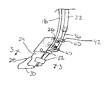
Figure 3 is a sectional view along the line 3-3 of Figure 2.
DETAILED DESCRIPTION
Referring to the accompanying drawing;;, there is illustrated a fertilizer
knife generally indicated by reference numeral 10. Tlne knife 10 is
particularly useful
for injecting anhydrous ammonia into the ground in agricultural applications.
The knife 10 is typically supported on an implement 12 of the type
including a frame 14 supported on wheels 16 for being towed across the ground.
A
plurality of impiement shanks 18 are provided which project downwardly and
forwardly into the direction of travel from the frame 14 towards the ground. A
fertilizer tank 20 is provided which is supported on the frame 14 and is
suitably
arranged for containing anhydrous ammonia therein under high pressure.
A fluid delivery system (not shown) is provided for communication
between the tank 20 and a plurality of delivery tubes 22 associated with the
shanks
18 respectively. Each shank 18 accordingly includes one of the delivery tubes
22
extending there alongside terminating adjacent the free end of the shank.
The knife includes a knife body 24 inc~iuding a shank mount formed
adjacent a top end thereof in the form of a set of apertures 26 which receive
suitable
fasteners in the form of bolts therethrough for securement to the respective
shank
18. The knife body tapers to become narrower adjacent a bottom edge with a
sharpened narrower leading edge 28 suitably arranged for cutting through the
ground to produce a furrow when the implement is towed across the ground in
use.
A bottom free end 30 of the knife body is inclined with respect to the leading
edge so
as to lie generally parallel to the ground when the leading edge extends
upwardly
and rearwardly.
Knife brackets 32 are mounted on the trailing edge of the l~cnife body at
spaced positions therealong, each in the form of a strap in a generally U-
shaped

CA 02432254 2003-06-11
-5-
configuration which is welded to the knife body at each end to respective
sides of the
body to define an aperture 34 between the bracket and the trailing edge of the
knife
body in the mounted position of the bracket on the knife. The apertures 34 are
thus
positioned rearwardly of the knife body for slidably receiving a dispensing
tube 36
into the apertures 34 of each bracket to prevent sagging of the dispensing
tube
relative to the knife body.
The dispensing tube 36 comprises a plastic tube having an outer
diameter of 3/8 of an inch. The plastic material forming the dispensing tube
36 is an
insulator having a low heat conductivity which is much lower than the heat
conductivity of the steel forming the knife body 24. A bottom end of the
dispensing
tube 36 is cut at an incline which matches the incline of the bottom end 30 of
the
knife body relative to the longitudinal direction thereof so that the bottom
end of the
dispensing tube similarly lies parallel to the ground.
A shank bracket 40 is provided which includes a base member with
mounting apertures arranged for bolting by the fasteners securing the knife
body to
the shank 18 to permit the shank bracket 40 to be selectively separable or
mounted
on without requiring welding operations. The shank bracket also includes an
aperture 42 formed therein which slidably receives an upper portion of the
dispensing tube 36 to position the dispensing tube rearwardly of the knife
body 24
and the respective shank 18 upon which it is supported.
In use the implement is towed across the ground in the conventional
manner while anhydrous ammonia is dispensed through the delivery tubes 22 to
the
respective dispensing tubes 36 of the knives 10 on the implement. The delivery
tubes 22 on the implement conventionally have an outer diameter of '%2 of an
inch
such that an interior diameter of the delivery tubes 22 snugly receives the
respective
dispensing tubes 36 therein. The plastic material and suitable brackets for

CA 02432254 2003-06-11
_g_
securement of the plastic material of the dispensing tube onto the knife
prevents
conduction of heat being drawn away from the knife body to the anhydrous
ammonia
flowing through the dispensing tube 36 and accordingly the plastic material of
the
dispensing tube prevents considerable freeze up of moist ground onto the knife
body
~ in use.
While one embodiment of the present irwention has been described in
the foregoing, it is to be understood that other embodiments are possible
within the
scope of the invention. The invention is to be considered limited solely by
the scope
of the appended claims.

Dessin représentatif
Une figure unique qui représente un dessin illustrant l'invention.
États administratifs

2024-08-01 : Dans le cadre de la transition vers les Brevets de nouvelle génération (BNG), la base de données sur les brevets canadiens (BDBC) contient désormais un Historique d'événement plus détaillé, qui reproduit le Journal des événements de notre nouvelle solution interne.

Veuillez noter que les événements débutant par « Inactive : » se réfèrent à des événements qui ne sont plus utilisés dans notre nouvelle solution interne.

Pour une meilleure compréhension de l'état de la demande ou brevet qui figure sur cette page, la rubrique Mise en garde , et les descriptions de Brevet , Historique d'événement , Taxes périodiques et Historique des paiements devraient être consultées.

Historique d'événement

Description Date
Demande non rétablie avant l'échéance 2006-06-12
Le délai pour l'annulation est expiré 2006-06-12
Inactive : CIB de MCD 2006-03-12
Réputée abandonnée - omission de répondre à un avis sur les taxes pour le maintien en état 2005-06-13
Demande publiée (accessible au public) 2004-12-11
Inactive : Page couverture publiée 2004-12-10
Inactive : CIB en 1re position 2003-08-06
Inactive : CIB attribuée 2003-08-06
Demande reçue - nationale ordinaire 2003-07-21
Inactive : Certificat de dépôt - Sans RE (Anglais) 2003-07-21

Historique d'abandonnement

Date d'abandonnement Raison Date de rétablissement
2005-06-13

Historique des taxes

Type de taxes Anniversaire Échéance Date payée
Taxe pour le dépôt - petite 2003-06-11
Titulaires au dossier

Les titulaires actuels et antérieures au dossier sont affichés en ordre alphabétique.

Titulaires actuels au dossier
ANTHONY W. NOWOSAD
Titulaires antérieures au dossier
S.O.
Les propriétaires antérieurs qui ne figurent pas dans la liste des « Propriétaires au dossier » apparaîtront dans d'autres documents au dossier.
Documents

Pour visionner les fichiers sélectionnés, entrer le code reCAPTCHA :


Pour visualiser une image, cliquer sur un lien dans la colonne description du document. Pour télécharger l'image (les images), cliquer l'une ou plusieurs cases à cocher dans la première colonne et ensuite cliquer sur le bouton "Télécharger sélection en format PDF (archive Zip)" ou le bouton "Télécharger sélection (en un fichier PDF fusionné)".

Liste des documents de brevet publiés et non publiés sur la BDBC .

Si vous avez des difficultés à accéder au contenu, veuillez communiquer avec le Centre de services à la clientèle au 1-866-997-1936, ou envoyer un courriel au Centre de service à la clientèle de l'OPIC.


Description du
Document 
Date
(aaaa-mm-jj) 
Nombre de pages   Taille de l'image (Ko) 
Description 2003-06-10 6 314
Abrégé 2003-06-10 1 23
Revendications 2003-06-10 4 164
Dessins 2003-06-10 1 16
Dessin représentatif 2003-10-02 1 7
Certificat de dépôt (anglais) 2003-07-20 1 158
Rappel de taxe de maintien due 2005-02-13 1 109
Courtoisie - Lettre d'abandon (taxe de maintien en état) 2005-08-07 1 175