Note : Les descriptions sont présentées dans la langue officielle dans laquelle elles ont été soumises.
CA 02437467 2003-08-05
WO 02/063807 PCT/US02/03189
RELATED APPLICATIONS
The present application is related to co-pending and commonly assigned U.S.
Patent
Applications S.N. 09/434,832, 09/434,815, 09/434,816, and 09,434,707, each
entitled "SYSTEM
AND METHOD FOR BROADBAND MILLIMETER WAVE DATA COMMUNICATION",
the disclosures of which is hereby incorporated herein by reference. The
aforementioned
applications are each a divisional of commonly assigned U.S. Patent No.
6,016,313 entitled
"SYSTEM AND METHOD FOR BROADBAND MILLIMETER WAVE DATA
COMMUNICATION" issued 18 January 2000 and currently undergoing two re-
examinations
under Application S.N. 90/005,726 and Application S:N. 90/005,974.
The present application is related to and is being concurrently filed with
commonly
assigned U.S. Patent Application S.N. entitled "SYSTEM AND METHOD FOR
DYNAMIC BANDWIDTH ALLOCATION", U.S. Patent Application S.N.
entitled "SYSTEM AND METHOD FOR DYNAMIC BANDWIDTH ALLOCATION IN A
POINT TO MULTIPOINT COMMUNICATION SYSTEM", U.S. Patent Application S.N.
entitled "SYSTEM AND METHOD FOR REAL TIME ADAPTIVE CAPACITY
SCHEDULING", U.S. Patent Application S.N. entitled "APPARATUS AND
METHOD FOR MANAGING BURST PROFILE CHARACTERISTICS IN TDM SYSTEMS",
and U.S. Patent Application S.N. entitled "SYSTEM AND METHOD FOR
DEMODULATOR STATE CONTROLLER", the disclosures of which is hereby incorporated
herein by reference. The present application claims the priority of co-pending
U.S. Provisional
Application S.N. 60/266,475 entitled "SOFTWARE PROVISIONAL APPLICATION", the
disclosure of which is hereby incorporated herein by reference.
CA 02437467 2003-08-05
WO 02/063807 PCT/US02/03189
BACKGROUND OF THE INVENTION
The present invention relates to communication systems and methods for which
acquisition and reacquisition of signals in different communication frames is
required.
More specifically, the disclosed inventive system and method applies to
wireless point-
to-multipoint time division multiple access communication systems which use a
repeating
frame format.
In multiple access communication systems, it is common to use a communication
hub, or network of hubs, to communicate with one or more sets of remote sites
("remotes'). Typically, such communication is done over an airlink in a
repeating frame
format protocol, i.e., a format where the communication is broken into
multiple frames so
as to allow access to the communication airlink by more than one remote site
at a time.
The frames typically contain a number of time slots where each of the time
slots in a
frame may transmit information from a separate remote during a particular
frame to
thereby give the impression of simultaneous communication between a hub and
plural
remotes. After a frame is transmitted/received, another frame starts. Each
frame
typically contains different information than the other frames, but not
necessarily so. The
continuous stream of frames and time slots allow for continuous communication
between,
for example, the hub and plural remotes, or between one hub and one or more
other hubs.
2
CA 02437467 2003-08-05
WO 02/063807 PCT/US02/03189
Conventional wireless systems that communicate between a hub and plural
remotes are known in the art as multiple access communication systems. One
type of
multiple access communication system is a time division multiple access
("TDMA")
system. In typical TDMA systems, time slots, or time segments, are organized
into
frames of multiple time slots. For example, ones of the plurality of remotes
may send
information, such as data, voice, multimedia, control signals, etc., or a
combination of the
foregoing, to the hub in a frame. Typically, each remote sending information
in a frame
is assigned a time slot within the frame. The hub also may be given the
opportunity
within a frame to transmit to one or more of the remotes. Information is
typically
transmitted to a specific remote or hub during the time slots in the frame
according to a
time slot assignment to the specific remote or hub.
Hubs and remotes may communicate via a duplexing scheme which allows for the
exchange of information in both directions across the airlink. Transmissions
from the
hub to the remote are termed "downlink" or "forward" transmissions.
Transmissions
from the remote to the hub are termed "uplink" or "reverse" transmissions.
Time
division duplex ("TDD") schemes, which are well known in the art, typically
divide a
frame into forward and reverse portions. The forward and reverse portions,
which are
generally equal in size, are the same size from frame to frame. Adaptive time
division
duplex ("ATDD") schemes allow for TDD frames to vary the relative sizes of the
forward and reverse portions of the frame depending on, for example, the
amount of
traffic to be communicated in each direction at a given time. ATDD systems are
3
CA 02437467 2003-08-05
WO 02/063807 PCT/US02/03189
described in U.S. Patent Applications S.N. 09/434,832, 09/434,815, 09/434,816,
and
09,434,707, each entitled "SYSTEM AND METHOD FOR BROADBAND MILLIMETER
WAVE DATA COMMUNICATION", each a divisional of U.S. Patent No. 6,016,313
entitled
"SYSTEM AND METHOD FOR BROADBAND MILLIIVViETER WAVE DATA
COMMUNICATION" issued 18 January 2000 and currently undergoing two re-
examinations
under Application S.N. 90/005,726 and Application S.N. 90/005,974.
Frequency division duplexing ("FDD") schemes, which are also well known in the
art, allow for duplexing between a hub and remote by separating the
transmissions
between the hub and remote in frequency space rather than in time.
In communication systems, such as a wireless communication system, the
receiver
and the transmitter must be synchronized in order for the receiver to make
sense of the
incoming data stream that was sent by the transmitter. For TDMA systems, it is
imperative that each remote transmitter send its information so as to be
received by the
hub receiver at the proper time. As is known in the art, the hub will
typically have a
phase lock loop circuit with a local oscillator, such as a voltage controlled
oscillator, that
generates a signal with the same frequency as the carrier wave sent by the
remote on
which the data is superimposed. In some systems, the hub may include a simple
input
node to receive a replicated carrier wave generated somewhere else than at the
hub. Part
of the synchronization process is the acquisition of the signal. Once a signal
is received
by the receiver, the signal must be acquired, i.e., the frequency and the
phase of the
incoming data must be known to the receiver so that the receiver circuitry can
determine,
4
CA 02437467 2003-08-05
WO 02/063807 PCT/US02/03189
for example, symbol timing so that the incoming data can be sampled at the
proper time.
Typical prior art systems acquire an incoming signal by use of a unique set of
data
bits, known as a "unique word", near the beginning of a message in a time
slot. The
unique word is known by the receiver at the hub. The hub receiver recognizes
the unique
word bits as they are received in the incoming signal and the hub adjusts its
internal
timing so as to be able to sample the incoming bits at the proper time. Prior
art systems
typically have to reacquire a signal from the same remote every frame by any
of a
number of known techniques, such as the use of a unique word contained within
the
signal sent in each time slot in each frame. The unique word takes up valuable
time in
the time slot that may be utilized for the transmission of data bits.
Therefore, the
presence of the unique word in each time slot is an inefficient use of the
airlink resource.
Additionally, the time required to reacquire a received signal slows down the
overall
effective data bit rate of the system.
Other prior art systems must reacquire each symbol from a remote by
calculating
the timing phase or determining the unique word for each symbol. However, such
systems are not efficient at reacquiring a later-received signal due to the
delays inherent
in the calculations required to acquire each symbol. Some of these prior art
systems have
a time slot dedicated to a particular remote so that the hub receiver always
knows the
sequence of reception of signals: time slot 1 always carriers signals from
remote A, time
slot 2 always carries signals from remote B, etc. Such prior art systems are
not efficient
when the amount of data sent between the different remotes to the hub changes
from
CA 02437467 2003-08-05
WO 02/063807 PCT/US02/03189
frame to frame. These systems also cannot operate in TDMA systems where there
is no
relationship between a particular remote and a given time slot.
TDMA point-to-multipoint communication systems, such as those described in the
references cited above, are designed to have more remote subscribers than time
slots per
frame. Consequently, for efficient communications between the hub and remotes
of such
a system, there is no relationship between a particular remote and a given
hub. For
example, in a system with four time slots per frame, remote A may transmit in
time slot 1
in a first frame, in time slot 3 in the next frame, in time slot 1 the next
frame, then time
slot 2, time slot 4, etc. It is to be understood that the above system is
exemplary only and
is not intended to be limiting in any way. The present invention can operate
with any
number of time slots per frame. Obviously, prior art systems that attempt to
derive
timing information about a remote from the location of the time slot in the
frame will not
operate efficiently, if at all, in the system described above.
Further complicating the acquisition problem are systems that operate with
varying baud rates. The baud rate may be defined as the number of symbols
transmitted
per frame. Prior art systems that attempt to reacquire in a later-received
frame a signal
from a remote by counting the number of symbols received from a previous frame
would
not perform correctly in a system with varying baud rates.
Thus there is a need for a system and method for communicating in a time
division
multiple access communication system operating with a repeating frame format
which,
after a signal from a first subscriber is acquired in a first frame, acquires
signals in
6
CA 02437467 2003-08-05
WO 02/063807 PCT/US02/03189
subsequent frames without relying on timing information contained within the
signal in
the subsequent frame to thereby overcome the limitations of prior art systems
and
methods. Additionally, there is a need for a system and method for
communicating in a
time division multiple access communication system operating with a repeating
frame
format which, after a signal from a first subscriber is acquired in a first
frame, acquires
signals in subsequent frames without relying on a calculation of the timing
phase for each
received symbol/signal.
One embodiment of the present invention avoids the problems and limitations of
the prior art by storing at the hub timing information for a signal in a first
frame from a
plurality of subscribers and using the stored timing information for a one of
the plural
subscribers for acquiring a signal in a later-received frame from that one
subscriber,
where such timing information is independent of any time slot information in
any of the
received frames.
Another embodiment of the present invention avoids the problems and
limitations
of the prior art by limiting the start of a time slot in any frame to an
integer number of
airlink timing units after the start of the previous time slot and/or frame.
Accordingly, it is an object of the present invention to obviate many of the
above
problems in the prior art and to provide a novel system and method for
communicating in
a repeating frame format between a hub and fixed remotes in a point-to-
multipoint time
division multiple access wireless communication system, where the frames
contain a
predetermined number of time slots and a predetermined number of airlink
timing units
7
CA 02437467 2003-08-05
WO 02/063807 PCT/US02/03189
and where the time slots contain an integer number of airlink timing units,
and where a
signal in a first frame from a one remote is acquired by any well-known
method, and
wherein the periodicity of the airlink timing units allows for the
reacquisition of signals
in later-received frames from the first frame without relying on timing
information
contained in the signals in the later-received frames.
It is another object of the present invention to provide a novel system and
method
for communicating in a repeating frame format between a hub and fixed remotes
in a
point-to-multipoint time division multiple access wireless communication
system, where
the number of ATUs per frame is a constant so as to allow for acquisition of a
signal from
a remote in frames subsequent to the frame of initial acquisition without
requiring timing
information within the signal in the subsequent frame.
It is yet another object of the present invention to provide a novel system
and
method for communicating in a repeating frame format between a hub and fixed
remotes
in a point-to-multipoint time division multiple access wireless communication
system,
wherein the size of the time slots within a frame is variable so long as the
time slots are
each an integer number of ATUs.
It is still another object of the present invention to provide a novel system
and
method for reacquiring a signal from one of a plurality of remote transmitters
in frames
subsequent to the frame of initial acquisition in a point-to-multipoint time
division
multiple access wireless communication system.
These and many other objects and advantages of the present invention will be
CA 02437467 2003-08-05
WO 02/063807 PCT/US02/03189
readily apparent to one skilled in the art to which the invention pertains
from a perusal of
the claims, the appended drawings, and the following detailed description of
the preferred
embodiments.
BRIEF DESCRIPTION OF THE DRAWINGS
Figure 1 is a notional view of a point-to-multipoint communication system with
plural hubs and plural remotes.
Figure 2 is a diagram of a repeating frame communication format showing a time
slot to frame relationship and the generalized components of a time slot. Also
depicted is
the changing time slot assignments for the remotes.
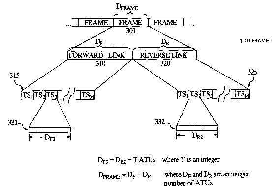
Figure 3 is a depiction of a time division duplex frame showing identical time
slot
durations.
Figure 4 is a depiction of an adaptive time division duplex frame showing
asymmetric time slot durations.
Figure 5 is a depiction of a reverse link of two time division duplex frames
(or
adaptive time division duplex frames) showing an integer number of airlink
timing units
for each asymmetric time slot. Also depicted is the changing time slot
assignments for
the remotes.
Figure 6 is a flow chart for reacquiring signals from a remote according to an
embodiment of the present invention.
Figure 7 is a functional block diagram of a portion of a hub receiver signal
path.
9
CA 02437467 2003-08-05
WO 02/063807 PCT/US02/03189
DESCRIPTION OF PREFERRED EMBODIMENTS
With reference to the drawings, like numerals represent like components
throughout the several drawings.
Figure 1 represents a typical wireless communication system for providing high
speed, broadband communication. The system in Figure 1 comprises the hubs 101,
102,
and 103, the remotes 150 through 154, and the communication backbone 160. The
communication backbone may any form of communication means, such as a fiber
optic
gateway or other broadband data grade connection, Tl communication lines, a
cable
communication system, the Internet, or the like. It should be understood that
the number
and organization of the hubs and remotes in Figure 1 is for exemplary purposes
only and
should not be seen as a limitation to the applicability of the present
invention in any way.
The hubs 101 and 102 communicate with each other via an air link while the
hubs 101
and 103 communicate with each other via the communication backbone 160. Each
of the
hubs communicates with its respect remotes via an airlink. The remotes may be
connected, for example, to a single PC, such as the PCs 130 or 131, or to a
network, such
as the local area networks 110. or 120. A complete description of an exemplary
system of
Figure 1 may be found in U.S. Patent Applications S.N. 09/434,832, 09/434,815,
09/434,816,
and 09,434,707, each entitled "SYSTEM AND METHOD FOR BROADBAND MILLIMETER
WAVE DATA COMMUNICATION", each a divisional of U.S. Patent No. 6,016,313
entitled
CA 02437467 2003-08-05
WO 02/063807 PCT/US02/03189
"SYSTEM AND METHOD FOR BROADBAND MILLIMETER WAVE DATA
COMMUNICATION" issued 18 January 2000 and currently undergoing two re-
examinations
under Application S.N. 90/005,726 and Application S.N. 90/005,974.
The number of remotes with which a given hub communicates may be greater than
the
number of time slots available per frame. For example, a preferred embodiment
may have up to
128 remotes communicating with a sector of a hub over frames that have a
maximum of 32 time
slots. Therefore, it is possible that a particular remote will not communicate
with the hub in the
same time slot from frame to frame, or a remote may not communicate with the
hub each frame.
It is advantageous in such a system that the hub be able to acquire the remote
in the shortest time
possible each time the remote sends a signal to the hub, regardless of the
time slot in the frame
over which the remote's signal is sent to the hub.
With reference directed to Figure 2, frames 1 through N are received at a hub,
such as the hub 101 in Figure 1 (not shown here for clarity), and are depicted
at 201 with
frames 2, 5, and N shown in exploded detail at 210, 211, and 212,
respectively. Each of
the exploded views 210, 211, and 212 depict time slots 1 through M as TSl
through TSM.
Also depicted are the time slot assignments for four remotes, R1, R2, R3, and
R4, which
are in communication with the hub. As can be seen from Figure 1, the remote
time slot
assignments may change from frame to frame. For example, R1 is in TSl in frame
2
while R, is in TS4 in frame 5. TSM of frame 2 is further exploded to show
typical
contents of an uplink time slot, such as the preamble 221, a unique word 222,
and the
payload 223, each of which perform typical functions as are well known in the
art.
Turning attention to Figure 3, a time division duplex ("TDD") frame 301 is
11
CA 02437467 2003-08-05
WO 02/063807 PCT/US02/03189
depicted with a forward link portion 310 and a reverse link portion 320. Each
of the link
portions is further exploded to show time slots 1 through M as TS 1 through
TSM as shown
at 315 and 325. The duration of TS3 in the forward link is shown pictorially
at 331, DF3,
and the duration of TSZ in the reverse link is shown pictorially at 332, DR2.
DF3 arid DR2
are shown as being equal and being an integer number of airlink timing units
("ATUs").
ATUs will be discussed in more detail below. Also shown is the duration of the
forward
link, DF, and the duration of the reverse link, DR. Figure 3 depicts a
symmetric TDD
frame, therefore DF = DR. The duration of the frame, D~A,~,~, is constant from
frame to
frame. Since the time slots are each an integer number of ATUs and there are
an integer
number of time slots per forward or reverse link, the forward and reverse
links are also
comprised of an integer number of ATUs. Similarly, each frame is compose of an
integer
number of ATUs which is a constant number. Each frame is comprised of the same
number of ATUs. This integer relationship of ATUs to time slots and frames is
important
to the operation of the disclosed inventive system and method.
With attention directed now to Figure 4, an adaptive time division duplex
("ATDD") frame 401 is depicted comprising the forward link 410 and the reverse
link
420. Figure 4 could also be viewed as an asymmetric TDD frame. Figure 4 is
similar to
Figure 3, and like numbers in the Figures represent like concepts. The
difference
between Figures 3 and 4 is that the forward and reverse links, 410 and 420,
respectively
in Figure 4, are not the.same duration. Additionally, the duration 431 of the
time slots
415 of the forward link is dissimilar to the duration 432 of the time slots
425 in the
12
CA 02437467 2003-08-05
WO 02/063807 PCT/US02/03189
reverse link. However, it is important to note that each of the time slots,
whether in a
forward link or reverse link, are an integer number of ATUs. Time slot
duration must be
an integer number of ATUs in order to practice the disclosed inventive system
and
method. Similarly, the duration of the forward and reverse links, although
different, are
each an integral number of ATUs. The duration of the frame 401 in Figure 4
does not
change and is the same number of ATUs as the duration of the frame 301 in
Figure 3.
Figure 5 depicts the reverse link of two frames, frame A at 501 and frame B at
502. Each reverse link comprises time slots 1 through M. The reverse link of
frame A
comprises the time slots TSA1 through TSAM. The reverse link of frame B
comprises the
time slots TSB1 through TSBM. Depicted with the time slots 1 through 4 of each
frame are
the time slot assignments for remotes 1 through 4, R1 through R4,
respectively, which are
in communication with a hub receiving the reverse link frames. Note that the
time slot
assignments for the remotes may change from frame to frame, as discussed
previously
with regard to Figure 2. Additionally, the time slot duration, denoted as DA;
for frame A
and DB; for frame B where i = 1 to M, may change from time slot to time slot
and frame
to frame so long as each time slot is an integer number of ATUs and the
reverse links are
an integer number of ATUs.
As shown in Figure 5, an ATU is the time required to transmit S symbols at a
baud
rate R. According to the inventive system and method, an ATU is the
granularity of the
system. ATUs are the building blocks of time slots and hence frames, i.e., an
ATU
defines the unit of time by which time slots are defined. Each time slot must
be an
13
CA 02437467 2003-08-05
WO 02/063807 PCT/US02/03189
integral number of ATUs, although each time slot in a frame need not be the
same
number of ATUs so long as each frame is a constant number of ATUs. By limiting
time
slots to integer numbers of ATUs, which means a time slot must begin an
integer number
of ATUs after the beginning of a previous time slot, the inventive system and
method can
exploit the timing inherent in this regularity to reacquire signals from a
remote without
relying on timing information within the signal.
Figure 6 is a block diagram illustrating a method according to the present
invention for reacquiring a signal from a remote. In the step 610, the hub
receives a first
signal, S1, in a first frame, Fl, from a first remote, designated R, for this
example. The
receiver at the hub demodulates S 1 by any known method in the art. The
demodulated
signal S1 is then sampled at step 620 at a predetermined sampling rate. The
sampling rate
is based on a predetermined integer number of samples taken per ATU. At step
630, S1 is
acquired by any known method in the art in order to get the timing
information,
alternatively known as the phase information, of R1, such as by use of a
unique word.
The timing information for R1 is stored at the hub in step 640 in a memory
module, such
as a random access memory, a register, or the like. At step 650, the hub
receives a
second signal, S2, from R1 and demodulates SZ by known methods in the art. The
timing
information for R,, derived from a previously-received signal or signals from
R1 such as
S1, is retrieved from memory, at step 660. The retrieved timing information
for R1 is
used to acquire signal SZ without the need for timing information that may be
contained
within SZ.
14
CA 02437467 2003-08-05
WO 02/063807 PCT/US02/03189
Figure 7 is a functional block diagram of a hub receiver according to the
inventive
system. A first remote sends a signal which is received at the hub. The first
remote, and
all other remotes in communication with the hub, operate with automatic
frequency
control circuitry so as to maintain a constant frequency output. Once the
signal from the
remote is received at the hub, an intermediate frequency ("IF") signal is
generated, as is
known in the art, which is input to the analog to digital converter 710
("ADC"). The
ADC samples the IF signal at a rate set by the sampler clock by known methods.
The
output of the ADC is sent to the matched filter 720 and then to the resampler
730. The
purpose of the resampler is to change the relative timing phase of the input
samples to the
resampler so as to sample the symbol at the optimum time, as will be described
in more
detail below. The output of the resampler is sent to the decimator 740 which
outputs an
integral number of samples per symbol. The output of the decimator is sent to
the
equalizer for further signal processing. The output of the decimator is also
fed back to
the timing recovery loop 750 which determines the timing phase offset from the
output of
the decimator. The timing phase offset is stored in memory 760 for later
retrieval and use
as discussed below. The output of the timing recovery loop 750, which is the
timing
phase offset, is fed into the resampler 730 and the decimator 740 in order to
sample the
input symbols for each at the proper time. Once the proper timing phase is
determined
for a remote, the hub no longer must calculate the timing of subsequent
symbols.
During operation, the sampler clock operates independently from the resampler
730 and the decimator 740. The sampler clock and the resampler sample an
incoming
CA 02437467 2003-08-05
WO 02/063807 PCT/US02/03189
symbol at the same rate (samples/symbol) but not necessarily at the same time
and/or
phase. As discussed above, the resampler and the decimator are controlled by
the timing
phase offset which is output from the timing recovery loop 750.
When a signal from a first remote is initially received at the hub, the signal
follows
the path in Figure 7. At the resampler 730, since the timing phase of the
signal from the
first remote is unknown, an estimate is made and refined until the signal from
the first
remote is acquired. For a preferred embodiment, the resampler (and the sampler
clock)
operate at 2.625 samples/symbol. The output of the resampler is sent to the
decimator
740 which outputs an integral number of samples/symbol. For a preferred
embodiment,
the output of the decimator is 2 samples/symbol. This output is then fed into
the timing
recovery loop 750 which determines the timing phase offset. The timing phase
offset is
then stored in the memory 760 for later retrieval and use. The output of the
timing
recovery loop sets a cadence for the resampler and the decimator so those
devices sample
the subsequent symbols from the first remote at the proper time.
Since the first remote is operating with automatic frequency control and
therefore
transmitting signals at a constant, predetermined frequency, and since the
granularity for
the system is known to be an ATU, which is of a known time duration, the
periodicity of
the timing recovery loop allows for reacquisition of a later-transmitted
signal from the
first remote without the need to calculate the timing of the later-transW
fitted signal. This
is due to the fact that the timing phase offset calculated for the first
remote will be the
timing phase offset for all later-transmitted signals from the first remote
since those
16
CA 02437467 2003-08-05
WO 02/063807 PCT/US02/03189
signals are constrained in frequency by the automatic frequency controller and
the time
slots for reception of the first remote's signals at the hub are constrained
to starting only
at the beginning of an ATU. The present inventive system and method exploits
the
resultant periodicity to acquire later-transmitted signals.
Since the hub may communicate with more than one remote, the hub must
initially
acquire and store the timing phase offset for each remote. For symbols/signals
received
from a second remote after the timing phase offset for the second remote has
been
determined, the hub can reacquire the signal from the second remote by
accessing the
timing phase offset for the second remote from the memory 760, and feed that
timing
phase offset into the resampler 730 and the decimator 740. The hub only needs
to have
one timing recovery loop for all the remotes with which it communicates so
long as the
timing phase offsets for each of the remotes in communication with the hub can
be stored
and retrieved for reacquiring later-received symbols/signals.
The basic design criteria for the inventive system and method is that the ATU
is
the finest granularity of the system. Each time slot, each forward/reverse
link, and each
frame contain an integer number of ATUs. One of skill in the art would
understand that a
different integer number of ATUs comprise a time slot than comprise a
forward/reverse
link, and yet a different integer number of ATUs comprise a frame. The ATU
itself is
defined as the time to transmit a predetermined number of symbols. One
embodiment of
the invention sets the ATU as the time to transmit sixteen symbols. The
preferred
embodiment adds the additional limitation of frame duration -as 1.5 msec.
17
CA 02437467 2003-08-05
WO 02/063807 PCT/US02/03189
As is known in the art, the baud rate is the number of symbols transmitted per
second. Therefore, different baud rates allow for different numbers of symbols
to be
transmitted per frame. The preferred embodiment has the following relationship
between
the baud rate and the number of ATUs per frame, where Mbaud is mega baud:
Baud Rate No. ATUs/frame
(Mbaud/sec)
10.752 1008
21.504 2016
40.064 3756
43.008 4032
A preferred embodiment samples at the hub the incoming signal from the remotes
at a rate such that there are 42 samples per ATU, which is 2.625 samples per
symbol.
Another preferred embodiment maintains a control ratio, the ratio of the
sampling rate to
the baud rate, of 5.25. One of skill in the art would realize that all of
these numbers may
be changed, while maintaining the proper interrelationships, so long as there
are an
integer number of samples per ATU and an integer number of ATU per time slot.
While preferred embodiments of the present invention have been described, it
is to
be understood that the embodiments described are illustrative only and that
the scope of
the invention is to be defined solely by the appended claims when accorded a
full range
of equivalence, many variations and modifications naturally occurring to those
of skill in
the art from a perusal hereof.
18