Sélection de la langue

Search

Sommaire du brevet 2442663 

Énoncé de désistement de responsabilité concernant l'information provenant de tiers

Une partie des informations de ce site Web a été fournie par des sources externes. Le gouvernement du Canada n'assume aucune responsabilité concernant la précision, l'actualité ou la fiabilité des informations fournies par les sources externes. Les utilisateurs qui désirent employer cette information devraient consulter directement la source des informations. Le contenu fourni par les sources externes n'est pas assujetti aux exigences sur les langues officielles, la protection des renseignements personnels et l'accessibilité.

Disponibilité de l'Abrégé et des Revendications

L'apparition de différences dans le texte et l'image des Revendications et de l'Abrégé dépend du moment auquel le document est publié. Les textes des Revendications et de l'Abrégé sont affichés :

  • lorsque la demande peut être examinée par le public;
  • lorsque le brevet est émis (délivrance).
(12) Demande de brevet: (11) CA 2442663
(54) Titre français: DISPOSITIF DE SECHAGE POUR MATERIEL IMPRIME
(54) Titre anglais: DRYING DEVICE FOR PRINTED MATERIAL
Statut: Réputée abandonnée et au-delà du délai pour le rétablissement - en attente de la réponse à l’avis de communication rejetée
Données bibliographiques
(51) Classification internationale des brevets (CIB):
  • B41F 23/04 (2006.01)
  • F26B 13/10 (2006.01)
  • F26B 21/00 (2006.01)
(72) Inventeurs :
  • MONKEWITZ, PETER A. (Suisse)
  • TRUONG, TRONG-VIEN (Suisse)
(73) Titulaires :
  • BOBST S.A.
(71) Demandeurs :
  • BOBST S.A. (Suisse)
(74) Agent: SMART & BIGGAR LP
(74) Co-agent:
(45) Délivré:
(22) Date de dépôt: 2003-09-25
(41) Mise à la disponibilité du public: 2004-04-01
Requête d'examen: 2003-09-25
Licence disponible: S.O.
Cédé au domaine public: S.O.
(25) Langue des documents déposés: Anglais

Traité de coopération en matière de brevets (PCT): Non

(30) Données de priorité de la demande:
Numéro de la demande Pays / territoire Date
2002 1640/02 (Suisse) 2002-10-01

Abrégés

Abrégé anglais


The drying disposal for a printed material (13), in strip or sheet,
uses a drying fluid propelled in the direction of the printed material (13)
through
nozzles (15), each of them equipped with one blowing opening (30) and meant
to blow a drying fluid or medium warmed by heating elements. Nozzles (15) are
arranged in an enclosed space of a drying device (12). The drying fluid or
medium presents, near the printed material (13), a turbulent flux that is
immediately produced at the exit of the blowing openings (30) of nozzles (15)
through transformation means (23) of a laminar flux in a turbulent flux. The
drying fluid or medium is extracted from the enclosed space of the drying
device (12) by the mean of an exhaust pipe (29) located between two
successive nozzles (15), preferably, but not compulsorily, equidistant to each
of
these aforesaid nozzles (15).

Revendications

Note : Les revendications sont présentées dans la langue officielle dans laquelle elles ont été soumises.


-5-
CLAIMS
1. Drying device for printed material (13), in strip or sheet, using a
drying fluid propelled in the direction of the printed material through
nozzles
(15) each one of them equipped with a blowing opening (30) aimed to blow a
drying fluid that have been previously warmth by a heating element (16), the
said nozzles (15) being arranged in an enclosed space (14) of drying device
(12), the said drying fluid showing a turbulent flux near the aforesaid
printed
material (13), the said drying fluid being then extracted from the enclosed
space
(14) through an exhaust pipe (29), characterized by the immediate creation of
the said turbulent flux at the exit of the blowing opening (30) of nozzles
(15).
2. Drying device for printed material (13) according to claim 1,
characterized in that the nozzles (15) are arranged perpendicularly to the
surface of the printed material (13) and close to this surface.
3. Drying device for printed material (13) according to claim 1,
characterized in that the nozzles (15) are inclined relatively to the surface
of the
printed material and arranged close to this surface.
4. Drying device for printed material (13) according to claim 1,
characterized in that the drying fluid is extracted from the enclosed space
(14)
through an exhaust pipe (29) located between two successive nozzles.
5. Drying device for printed material (13) according to claim 4,
characterized in that the exhaust pipe (29) is located, between two successive
nozzles (15), equidistant to each of the said nozzles (15).
6. Drying device for printed material (13) according to claim 1,
characterized in that the transformation means (23) of a laminar flux in a
turbulent flux are mechanically driven.
7. Drying device for printed material (13) according to claim 6,
characterized in that the mechanical means of transformation of a laminar flux
in a turbulent flux are made up of a notched structure (33) installed at the
extremity of at least one of the sides of the blowing opening (30) and that
the
said notched structure (33) is located parallel to the side of the blowing
opening
(30).
8. Drying device for printed material (13) according to claim 7,
characterized in that the notched structure (33) is established in the
extremity of
the downstream side of the blowing opening (30), relative to the moving
direction (26) of the printed material (13).

-6-
9. Drying device for printed material (13) according to claim 7,
characterized in that the mechanical means of transformation of a laminar flux
in a turbulent flux are made up of a piece with a notched structure (33) lay
off
on at least one of the side of the blowing openings (30).
10. Drying device for printed material (13) according to claim 9,
characterized in that the notched structure (33) is positioned with angle from
0
up to 90° relative to at least one of the side of the blowing openings
(30).

Description

Note : Les descriptions sont présentées dans la langue officielle dans laquelle elles ont été soumises.

CA 02442663 2003-09-25
- 1 - JBF283
DRYING DEVICE FOR PRINTED MATERIAL
The present invention relates to a drying device for printed material,
more precisely to a device using a drying fluid propelled in the direction of
the
printed material through nozzles.
In the drying devices generally in use, the printed material, under
the shape of sheets or strips, goes through a drying device including two
boxes
in which are arranged a series of nozzles through which a drying fluid,
generally
hot blast, is propelled on the printed side of the printed material. After
being in
contact with the printed material, this hot blast is then extracted from the
drying
box by suction. In this kind of drying device, the hot blast is blown in the
direction of the printed areas of the printed material by nozzles arranged
perpendicularly to the plane defined by the material in strip or sheet. The
fast
speed of the printed material gives rise to a laminar flux close to its
surface,
isolating a little bit the printed layer from the ambient air of the drying
device.
This laminar flux has then to be crossed by the air coming out of the nozzles
in
order to insure an efficient result of the hot blast on the printed material.
One
solution to facilitate the transmission of the blown air from the nozzles to
the
printed layer lies in the destruction of the laminar flux through the creation
of
turbulences in its surroundings. Such a solution is described in patent US 4,
779, 555, in which the hot blast, blown in the direction of the printed
material
through nozzles, is then returned by the said printed material in the
direction of
several deflectors placed around the nozzles in order to create turbulences in
the laminar flux present around the printed surface.
The disadvantage of this device lies in the requirement of both
nozzles and deflectors in order to create a turbulent flux around the printed
surface of the printed material. Furthermore, this combination presents the
disadvantage of not creating a continuous turbulent flux at the proximity of
the
printed material because at the location of the nozzle, especially at its
level, the
flow of the air blast that gets in contact with the material in strips or
sheets
presents some laminar characteristics.
The aim of the present invention consists in providing a simple
design drying device for printed material, in strips or sheets, using simple
nozzles that are not linked to complementary deflectors.

CA 02442663 2003-09-25
- 2 - JBF283
This aimed is realised thanks to a drying device of a printed
material in strips or sheets such as defined in claim 1.
The invention will be more understandable along the following
description that will be achieved in relation with the enclosed drawings that
illustrate, schematically and as an example, one type of execution of this
drying
device.
- Figure 1 is a schematic cutting view of a drying device according
to the present state of the technology,
Figure 2 is a schematic partial cutting view of a drying device,
- Figure 3 is a schematic partial cutting view according to the axis
III-III of figure 2,
Figure 4 is a cutting view showing the location of the nozzles in
the drying device,
- Figure 5 is a cutting view of one of the nozzles of the drying
device.
- Figure 6 represents a perspective view of one execution of one of
the nozzles of the drying device.
Figure 1 is a schematic cutting view of the housing 2 of a drying
device, according to the known state of the art, in which the printed material
is
running opposite to the nozzles 3, which comprises two blowing ports 4, 5.
Each of these blowing ports 4, 5 is associated to a series of deflectors 6, 7.
The
drying fluid with laminar flux 8, getting out of the blowing ports 4, 5 is
propelled
in the direction of the printed material through a nozzle 3 and then sent back
by
the surface of the printed material 1 in the direction of several deflectors
6, 7
located around nozzles 3 in order to create an effect of turbulence in the
existing laminar flux around the printed surface. This drying fluid with
turbulent
flux 9 reaches the printed material 1 and destroys the laminary
characteristics
of the existing flux at proximity of the surface of the printed material 1 so
that
the drying fluid could get mixed to the solvent resulting from the deposit of
ink
on the printed material and thus favours the suppression of solvents present
over this printed material. This mixture 10 of drying fluid and solvents is
then
aspirated by an exhaust pipe 11.
Figure 2 is a schematic cutting view of a conventional drying device,
in which a printed material 13 is running. This drying device comprises an
enclosed space 14, in which are located nozzles 15 intended to blow a drying
fluid warmed by heating elements 16. The drying fluid circulation is
illustrated

CA 02442663 2003-09-25
- 3 - JBF283
by arrows 17. Once loaded with solvents, the drying fluid is aspired by an
exhausting pipe 18 with the help of a first aspiration mean 19 that could be,
for
example, a fan. A part 20 of the mixture formed by the drying fluid and the
solvents is drained out through a pipe 21 linked to a second aspiration mean
(not illustrated). The rest of the mixture 22 is recycled within the enclosed
space
14 (i.e. figure 3).
Figure 3 is a schematic partial cutting view according to the line III-
III of Figure 2, in which the same reference digits are used to indicate the
various elements of the drying device. In this illustration of the drying
device, we
can note that the draining of the drying fluid loaded by solvents is realised
at the
centre of the device and that this flow of drying device has a direct impact
on
the printed surface of the printed material through the medium of its other
side
that could be possibly unprinted.
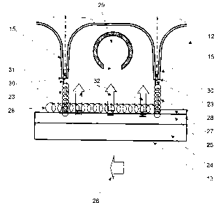
Figure 4 is a cutting view illustrating a possible disposition of
nozzles 15 of the drying device 12. In this figure, only two nozzles have been
represented. Each of these nozzles 15 is kitted out with means 23 of
transformation of the flux of the drying fluid that is laminar in nozzle 15
and then
becomes turbulent directly after getting out of nozzle 15. This turbulent flux
is
represented by the reference digit 28. The printed material 13 comprises a
support 24, generally made up of cardboard or any other material that can
possibly receive a layer of ink 25 loaded with solvents. The printed material
13
runs at fast speed in the direction indicated by arrow 26, producing a laminar
air
layer 27 that has to be broken in order to facilitate the evacuation of the
solvents and thus ensure the efficiency of the drying process. The mixture
made up of drying fluid and solvents, indicated by 32, is then aspired by an
exhausting pipe 29 located between two successive nozzles 15. This exhaust
pipe 29 can be made up of a simple tube. The location of the exhaust pipe 29
is
preferably equidistant to each of the two successive nozzles 15. We could, of
course, chose to locate this exhaust pipe 29 at any distance from each of the
nozzles 15. Openings 30 of nozzles 15 are presented in the form of a slot that
stretches ail along nozzles 15. The exhaust pipe 29 comprises an opening 31
that also stretches all along exhaust pipe 29 corresponding to the length of
nozzles 15.
Figure 5 is a cutting view of a nozzle 15 of the drying device 12.
The opening 30 of nozzle 15 is equipped with a mechanical mean 23 of
transformation of the flow of the drying medium flux. This mechanical mean 23

CA 02442663 2003-09-25
- 4 - JBF283
of transformation of the flow of the drying medium flux is presented here in
the
form of a notched structure 33 directly tooled at one side of the extremity of
opening 30 of nozzle 15. We could also imagine to tool this crenelated
structure
33 at each sides of the extremity of opening 30 of nozzle 15. Preferably, the
notched structure 33 is placed parallel to the downstream side; relative to
the
moving direction 26 of the printed material, of the extremity of opening 30,
in
other words parallel to the direction of the drying fluid in nozzle 15 (i.e.
figure 4).
However, an inclined notched structure with an angle from 0 up to 90°
relative
to the side of the extremity of the opening 30 can be taken into
consideration. A
perpendicular arrangement of the notched structure 33 relative to the side of
the extremity of opening 30, in other words, perpendicularly to the direction
of
the drying fluid in nozzle 15, can also be taken into consideration (i.e.
figure 5).
We note that we could also plan to lay off a piece with notched structure on
one
side of opening 30 in the case, for example, of a "retrofit" on one existing
nozzle
with slot. It has been shown through workshop test that a tooth-shaped notched
profile generates a high intensity turbulent flow allowing to ensure an
excellent
destruction of the laminar flux located near the printed material. This
destruction thus allows a significant improvement in the drying time of the
printed material when this latest moves with a speed from 100 up to
1000m/min. In the execution that has just been described, nozzles 15 are
arranged perpendicular to the surface of the printed material 13 and close to
this surface. An inclined disposition of nozzle 15 relative to the surface of
the
printed material 13 can also be taken into consideration. Of course, the
invention is not limited to this example. In the border-fine case and if
necessary,
each extremity of openings 30 of nozzles 15 could be equipped with two
notched structures 33.
Figure 6 represents a perspective view of one execution of one of
the nozzles 15 of the drying device 12. The opening 30 of nozzle 15 is
equipped with a mechanical mean 23 of transformation of the flow of the drying
medium flux. This mechanical mean 23 of transformation of the flow of the
drying medium flux is presented here perpendicular to the drying fluid
direction
through the opening 30 of nozzle 15. The mechanical mean 23 of
transformation could also be located parallel to the drying fluid direction
through
the opening 30 of nozzle 15 (i.e. figure 4).

Dessin représentatif
Une figure unique qui représente un dessin illustrant l'invention.
États administratifs

2024-08-01 : Dans le cadre de la transition vers les Brevets de nouvelle génération (BNG), la base de données sur les brevets canadiens (BDBC) contient désormais un Historique d'événement plus détaillé, qui reproduit le Journal des événements de notre nouvelle solution interne.

Veuillez noter que les événements débutant par « Inactive : » se réfèrent à des événements qui ne sont plus utilisés dans notre nouvelle solution interne.

Pour une meilleure compréhension de l'état de la demande ou brevet qui figure sur cette page, la rubrique Mise en garde , et les descriptions de Brevet , Historique d'événement , Taxes périodiques et Historique des paiements devraient être consultées.

Historique d'événement

Description Date
Inactive : Morte - Aucune rép. dem. par.30(2) Règles 2007-07-24
Demande non rétablie avant l'échéance 2007-07-24
Inactive : Abandon. - Aucune rép dem par.30(2) Règles 2006-07-24
Inactive : CIB de MCD 2006-03-12
Inactive : Dem. de l'examinateur par.30(2) Règles 2006-01-24
Demande publiée (accessible au public) 2004-04-01
Inactive : Page couverture publiée 2004-03-31
Inactive : CIB en 1re position 2003-11-06
Lettre envoyée 2003-10-27
Inactive : Certificat de dépôt - RE (Anglais) 2003-10-27
Lettre envoyée 2003-10-22
Demande reçue - nationale ordinaire 2003-10-22
Toutes les exigences pour l'examen - jugée conforme 2003-09-25
Exigences pour une requête d'examen - jugée conforme 2003-09-25

Historique d'abandonnement

Il n'y a pas d'historique d'abandonnement

Taxes périodiques

Le dernier paiement a été reçu le 2006-06-06

Avis : Si le paiement en totalité n'a pas été reçu au plus tard à la date indiquée, une taxe supplémentaire peut être imposée, soit une des taxes suivantes :

  • taxe de rétablissement ;
  • taxe pour paiement en souffrance ; ou
  • taxe additionnelle pour le renversement d'une péremption réputée.

Les taxes sur les brevets sont ajustées au 1er janvier de chaque année. Les montants ci-dessus sont les montants actuels s'ils sont reçus au plus tard le 31 décembre de l'année en cours.
Veuillez vous référer à la page web des taxes sur les brevets de l'OPIC pour voir tous les montants actuels des taxes.

Historique des taxes

Type de taxes Anniversaire Échéance Date payée
Requête d'examen - générale 2003-09-25
Taxe pour le dépôt - générale 2003-09-25
Enregistrement d'un document 2003-09-25
TM (demande, 2e anniv.) - générale 02 2005-09-26 2005-04-08
TM (demande, 3e anniv.) - générale 03 2006-09-25 2006-06-06
Titulaires au dossier

Les titulaires actuels et antérieures au dossier sont affichés en ordre alphabétique.

Titulaires actuels au dossier
BOBST S.A.
Titulaires antérieures au dossier
PETER A. MONKEWITZ
TRONG-VIEN TRUONG
Les propriétaires antérieurs qui ne figurent pas dans la liste des « Propriétaires au dossier » apparaîtront dans d'autres documents au dossier.
Documents

Pour visionner les fichiers sélectionnés, entrer le code reCAPTCHA :


Pour visualiser une image, cliquer sur un lien dans la colonne description du document. Pour télécharger l'image (les images), cliquer l'une ou plusieurs cases à cocher dans la première colonne et ensuite cliquer sur le bouton "Télécharger sélection en format PDF (archive Zip)" ou le bouton "Télécharger sélection (en un fichier PDF fusionné)".

Liste des documents de brevet publiés et non publiés sur la BDBC .

Si vous avez des difficultés à accéder au contenu, veuillez communiquer avec le Centre de services à la clientèle au 1-866-997-1936, ou envoyer un courriel au Centre de service à la clientèle de l'OPIC.


Description du
Document 
Date
(aaaa-mm-jj) 
Nombre de pages   Taille de l'image (Ko) 
Abrégé 2003-09-24 1 22
Description 2003-09-24 4 224
Revendications 2003-09-24 2 70
Dessins 2003-09-24 4 77
Dessin représentatif 2003-11-16 1 11
Accusé de réception de la requête d'examen 2003-10-21 1 173
Courtoisie - Certificat d'enregistrement (document(s) connexe(s)) 2003-10-26 1 106
Certificat de dépôt (anglais) 2003-10-26 1 159
Courtoisie - Lettre d'abandon (R30(2)) 2006-10-01 1 167