Note : Les descriptions sont présentées dans la langue officielle dans laquelle elles ont été soumises.
CA 02443799 2003-10-O1
1
M~CRC~w~ P~>~~~,T ~R~ss ~,ss~
Ia IELD oh THE INVENTI~N
The present invention relates to systems and methods of forming composite wood
products and more specifically to systems and methods of forming composite
wood
products using a microwave preheat press assembly.
BACKGROUND oF' THE ~NVENTI~N
Many processes are known in the art for forming a composite wood element
product from a composite mat assembly of resin coated wood elements. For
example,
steam and microwave energy have been used in conjunction with a variety of
press
assemblies to heat the mat assembly to about the cure; temperature of the
resin and
compress the mat assembly to a desired final dimension. However, the designs
of the
prior press assemblies are relatively inefficient.
Steam injection heating sources unduly limit the size of the composite wood
element products that can be formed. The heat carried by the steam must
naturally
IS conduct into the central portion of the product to raise the product to the
cure temperature.
Natural flow hrough a wood product is limiteel to certain thicknesses for
certain products.
Products over 5 inches thick can be very difficult to evenly heat. Further,
steam injection
presses are fixed in length and are not continuous in operation, limiting the
length of the
product. Thus, steam injection heating does got allow the production of
relatively larger
wood element products. By limiting the size of product that can be produced
from a given
press assembly the press assemblies ultimate utility is limited.
Traditional microwave heating systems have helped solve some of the heat
transfer problems. However, the design of these microwave heating systems
creates
another problem. More specifically, current designs have no balance between
the time at
which a mat assembly reaches the cure temperature and the time in which the
same mat
assembly reaches a fully compressed state. The result is either a mat assembly
where the
resin is cured before reaching final compression or a failure to bring the mat
to the
optimal temperature at all. The percentage of the energy that can be delivered
by preheat
is thus limited. In both cases an undesirable result is attained.
Press assemblies using microwave applicators directing microwave energy into
the sides of the mat assemblies have been developed in an attempt to address
these issues.
However, the side application systems have their limits as well. Placing a
microwave
waveguide assembly within a press limits the type of press assemblies that can
be used.
More specifically, many press assemblies are designed such that it is
physically
impossible to place a waveguide assembly at the side of the press.
Consequently, press
CA 02443799 2006-06-05
2
assemblies that may otherwise be highly desirable for other reasons may be
prevented
from being used by their design.
Examples of various microwave curing systems are US 5,228,947 issued July 20,
1993, US 6, 290,809 B1, issued Sept 18, 2001, LJS 6,242,726 B1, issued June 5,
2001, US
S 4,020,311, issued April 26, 1977, US 4,456,498, issued June 26, 1984 and US
6,176,951
B 1, issued January 23, 2001.
SUMMARY OF THE INVENTION
The present invention relates to an improved system and method for applying
microwave energy for curing a composite wood :product within a press assembly.
According to a first embodiment of the present invention, there is provided a
microwave
preheat press. The microwave preheat press comprises a first and a second
press section defining
therebetween a press passage and a compression belt nnoveable along the press
passage contiguous with
one of the press sections. The compression belt has an entrance section and
the press passage have an
initial compression section and a final compression secaion. The microwave
preheat press further
includes a microwave generator and a microwave waveguide applicator structure
assembly disposed
along the entrance section adjacent the initial compression section. The
microwave waveguide
applicator structure assembly is configured to direct microwave energy from
the generator into the
initial compression section. The microwave preheat press further includes a
choke configured to inhibit
arcing between the microwave waveguide assembly and the compression belt.
According to a further embodiment of the prescent invention, there is provided
a method of
forming a composite wood element product. The method comprises introducing a
mat assembly of
discrete wood elements coated with a resin into an initial compression section
of a press, the press
having a first and a second press section defining there;between a press
passage and a compression belt
moveable along said press passage contiguous with one of said press sections
directing microwave
energy from a microwave waveguide assembly into the mat assembly while the mat
assembly is within
the initial compression section; compressing and curing the composite wood mat
assembly into a final
compression state; and inhibiting arcing between the microwave waveguide
assembly and the
compression belt.
BRIEF DESCRIPTION OF THE DRAWIrTGS
The preferred and alternative embodiments of the present invention are
described in detail below with reference to the following drawings.
FIGURE 1 is a side view of the prEas assembly with microwave pre-heat
according to the present invention;
FIGURE 2 is side view of another embodiment of the present invention;
FIGURE 3 is a top schematic view of various aspects depicted in FIGURE 1;
FIGURE 4 is perspective view of an embodiment of the present invention;
FIGURE 5 is perspective view of another embodiment of the present invention;
FIGURE 6 is perspective view of ye;t another embodiment of the present
invention; and,
FIGURE 7 is perspective view of additional embodiment of the present
invention;
CA 02443799 2003-10-O1
3
DETAILED DESCRIPTION OF THE INVENTION
The present invention provides a system and method for forming composite wood
element products using a microwave preheat. By way of overview, and with
references to
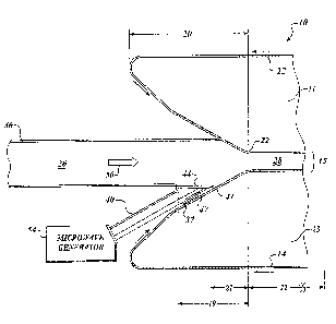
FIGURE l, one presently preferred embodiment includes a microwave preheat
press 10.
The microwave preheat press 10 includes a first press section 11 and a second
press
section 13 that define a press passage 15 therebetween. The press passage 15
is
configured to define a preheat section I9, an initial compression section 21
and a final
compression section 22. A microwave impervious compression belt I2, 14 is
contiguous
each press section I I, 13, respectively. A microwave generator 54 is used to
generate
microwave energy. A microwave waveguide applicator stricture assembly 40 is
adjacent
the initial compression section 21 and is configured to direct microwave
energy from the
microwave generator 54 into the initial compression section 21. Specific
details of the
microwave preheat press 10 are described in more particularity below.
Referring now to FIGURE 1, the present invention is preferably used to form
composite wood element products 28 from a mat assembly 26. The mat assembly 26
preferably comprises an arrangement of wood elements, such as strands, chips,
strips,
veneer or particles coated with a resin having a cure temperature, and that
can be
subjected simultaneously to pressure and microwave energy to form a composite
wood
element product 28. Suitable, non-limiting examples of such composite wood
element
products 28 include particleboard, fiberboard, waferboard, plywood, oriented
strand
board, laminated veneer lumber, parallel strand lumber, and laminated beams.
The
dimensions of the composite wood element products 28 formed by the present
invention
will be a matter of choice within the discretion of those skilled in the art.
The resin used to coat the wood elements of the neat assembly .26 is
preferably an
alkaline phenolic resin. However, any adhesive whose rate of cure is
accelerated by the
application of heat may be used with the present invention. Non-limiting
examples of
such resins are water soluble and non-water-soluble alkaline and acidic
phenolic resins,
resorcinol-formaldehyde resins, urea-formaldehyde resins, and isocyanate
resins. The
resins may be applied to the wood elements in any desired amount, or as
necessary to
form the specific compressed composite wood element product.
Continuous belt-type presses employable with the present invention are known
in
the art. As such, a detailed description of their structure is not necessary
fox the
understanding of this invention. The continuous press used in the present
invention
generally includes a first press section 11 and a second press section 13. The
press
sections I1, 13 are spaced apart to form a press passage 15 therebetween
through which
the mat assembly 26 may be passed. Suitable examples of press-types useable
with the
present invention are continuous presses made by Metso or Dieffenbacher.
CA 02443799 2003-10-O1
4
The first and second press sections 11, 13 define an entrance section 20. The
entrance section 20 is suitably arranged to receive the :chat assembly 26.
Part of the
entrance section 20 is an initial compression section 21. The initial
compression section
21 is considered that part of the press where the mat assembly 26 is being
compressed, but
has not yet been fully compressed. The final compression section 22 is the
press section
wherein the mat assembly 26 is at a full compressed state.
The compression belts 12, 14 are preferably stainless steel belts. However,
other
types of metal belts such as molybdenum belts may be used. Further, the
compression
belts 12, I4 may optionally be coated with a plastic material (not shown). For
example,
1Q stainless steel press belts coated with a film of polytetrafluoroethylene
may be used.
Alternatively, compression belts I2, 14 having a metal coating on a non-
metallic support
may be used.
The microwave waveguide applicator structure assembly 40 is preferably
positioned adjacent one of the compression belts 12, 14 so that the leading
end 41 is
I5 substantially in contact with their respective belts I2 and 14. Contact is
not required
within the scope of the invention but it is preferable to be as close as
practical. Separations
of many inches are acceptable. The :microwave waveguide applicator structure
assembly
40 is configured to direct microwave energy from the microwave generator 54
through
window 44 and into mat assembly 26 while the mat assembly 26 is within the
initial
20 compression section 2I.
As best illustrated in FIGURES I and 2, suitable chokes 45, 47 may be
positioned at the leading ends 39, 41 to inhibit arcing between the micrawave
waveguide
assembly applicator structure 38, 40 and their adjacent belt 12, 14,
respectively. The
structure of such chokes 45, 47 is well known in the art and may be of any
suitable form.
25 Also, to insure proper positioning, the microwave waveguide applicator
structure
assembly 40 may be provided with any commonly used wear plate 35, 37, or
similar
device. Further, suitable windows 42, 44 rr3~ay also be used to allow the
entrance of
microwave energy while providing support for the mat assembly 26. Also, in the
regions
around the microwave waveguide applicator structure assembly 40, suitable
microwave
30 type structures 52, such as dielectric spacers (FIGURE 3) may be used to
help control the
microwave energy.
Optionally, microwave heating in the press may be supplemented by heating the
press belts conventionally, e.g.; by heating platens (not shown) over which
the belts may
run, using, for example, steam or oil. The platen heating can both increase
the final rate of
35 cure and prevent the press surfaces from prematurely cooling the pressed
assembly.
Means for implementing such conventional press heating are well known in the
art.
The number and overall arrangement of the microwave waveguide applicator
structure assembly 40 employed with the present invention is not intended to
limit the
CA 02443799 2003-10-O1
present invention. More specifically, FIGURE 1 discloses only one microwave
waveguide applicator structure assembly 40 located on the bottom of the
microwave
preheat press I0. However, the microwave waveguide applicator structure
assembly 40
could just as easily be placed on the top. Alternatively, two or more
independent
5 microwave generators 54 may be used with separate waveguide applicator
structure
assemblies 38b, 40b. These multiple sources may be arranged on the same or
opposite
sides of the press passage 15. FIGURE 2, depict an arrangement where a .
single
microwave waveguide applicator structure assembly 38b, 40b is located on both
the top
and bottom of the microwave preheat press 10. FIGURES 6 and 7 depict another
possible
arrangement, where multiple microwave waveguide assembles 38c, 40c, 38d and
40d are
employed on a single side of the microwave preheat press 10. Additionally,
combinations
of these embodiments (not shown) also considered within the scope of this
invention.
As depicted in FIGURE 3, it is preferable that when multiple points of
application
of the microwave energy are used that the points be staggered in the direction
of 50 of the
mat 26 entering press IO by waveguide spacing 56. Ire a preferred embodiment,
the
waveguide spacing 56 is chosen to yield a substantially uniform heating
pattern 64a, 64b,
and 64c is achieved. However, the amount of waveguide spacing 56 is variable
and may
be determined by those skilled in the art. The wave guides 38 and 40 and the
windows 42
and 44 may also be laterally offset by a waveguide offset 58, as best seen in
FIGURE 3.
It will be appreciated that both the waveguide spacing 56 and the waveguide
offset 58
may be selected to achieve a more even heating pattern 64.
To this end, the waveguide offset 58 is preferably equal to about ~/z the
waveguide
width. In this manner, the peaks of energy from one window 42 are aligned with
the
valleys of the energy peaks applied through the other window 44 and vice versa
thereby
more uniformly apply microwave energy across the lay-up.
In a presently preferred embodiment, a microwave generator 54 producing
microwave energy at a frequency of 915 MHz is preferred. However, other
microwave
frequencies are considered within the scope of this invention. For example, it
has been
found that frequencies as low as about 95 MI~z can be employed. The upper
frequency
limit is not critical and is set by practical considerations, since there is a
direct relationship
between the optimum size of a waveguide and the frequency of the
electromagnetic wave
that can be conducted through it. Accordingly, any microwave frequency ranging
from at
least about 95 MHz is considered within the scope of this invention.
Commercially available microwave generators 54 which may be effectively
employed in the practice of the invention include, inter alia, Cober
Electronics and
Microdry Magnetrons having a power output of 75-100 kW and operating at 915
MHz, or
klystrons which are available at a variety of power outputs and frequencies.
CA 02443799 2003-10-O1
6
The amount of microwave energy applied to the mat assembly 26 is variable and
will depend upon various factors such as the nature of the wood elements and
the
properties of the resin coating. Regardless, the amount of microwave energy
applied to
the mat assembly is preferably an amount sufficient to bring the mat assembly
26 to a
temperature at least equal to the cure temperature of the resin while the mat
assembly is
still within the initial compression section 21. Preferably., the mat assembly
26 is brought
up to at least the cure temperature at the time the mat assembly enters the
final
compression section 22. Alternatively, the mat assembly 26 may be brought to
above the
cure temperature after the mat assembly 26 enters the final compression
section 22.
Again, alternatively the mat may be brought to a temperature less than the
cure
temperature and the hot platens of the press will supply the final energy
needed to cure the
assembly. For some products this is preferred and it is within the scope of
the invention.
These results are accomplished by controlling several variables.
One variable that is controlled to achieve the desired heating of the mat
assembly
26 is by moving the mat assembly 26 past the microwave sources at a suitable
linear
speed. One skilled in the art may determine linear speeds. 13y way of non-
limiting
example, when using phenol-formaldehyde resins, the linear rate may be
controlled so the
temperature for mat assembly 26 may range from about 100° C to about
170° C. In a
preferable arrangement the temperature may be within a range from about
110° C to about
150° C. More preferably the mat assemblies 26 are heated to a range
from about 115° C
to about 120° C. In applications where finishing the curing is best
done in the press
temperature ranges from about 80 degrees C to about 98 degrees C may be
preferred.
The linear feed rate at which the mat assembly 26 enters the microwave preheat
press 10 is variable and is dependent upon the nature of the composite wood
element
product 28 being formed. In a presently preferred embodiment, a linear feed
rate within
the microwave preheat press 10 will range from about 0.5 feet per minute to
about 150
feet per minute. In a particular embodiment, the linear feed rate is from
about 1 to about
feet per minute. However, the present invention is not limited by the linear
feed rate.
As such, feed rates above and below the preferred feed rates are considered
within the
30 scope of this invention.
Another variable that is controlled to achieve the desired heating of the mat
assembly 26 is the control of the microwave wavefarm. It is preferable for the
microwaves to be propagated in the waveguide assembly 40 in a TEND mode, where
N is
any integer. In a particular embodiment the N is equal to l, yielding a TEIO
made.
However, a TEND mode where N is any integer greater than one is also within
the scope of
this invention. Additionally, a waveguide assembly 40 producing a waveform
having a
TEoN mode is also considered within the scope of this invention. In this
particular
embodiment, the N is also equal to 1, or any integer greater than 1.
CA 02443799 2003-10-O1
7
Referring now to FIGURES 4 - 7, the microwave waveguide applicator structure
assembly 40 is also preferably configured such that the electric vectors 65,
65a, 65b and
65c are oriented substantially perpendicular to direction of travel 50 of the
mat assembly
26. As will be understood by those having skill in the art, there are two
planes in which a
vector may be perpendicular to a third plane. As such, FIGURE 5 and 7 depict
various
orientations for the electric vectors 65.
While the preferred embodiment of the invention has been illustrated and
described, as noted above, many changes can be made without departing from the
spirit
and scope of the invention. Accordingly, the scope of the invention is not
limited by the
disclosure of the preferred embodiment. Instead, the invention should be
determined
entirely by reference to the claims that follow.