Note : Les descriptions sont présentées dans la langue officielle dans laquelle elles ont été soumises.
CA 02449399 2003-12-03
WO 02/099231 PCT/US02/21239
Dispensing method using wireless coupling
TECHNICAL FIELD
The present invention relates generally to a method for the selective removal
of inventoried
items.
BACKGROUND ART
This invention relates generally to devices and systems for controlled
dispensing of
medications, therapeutic agents, or other pharmaceutical items in a hospital
environment, nursing
home, or the like. More particularly, this invention relates to an improved
security or locking
system to be used in combination with existing medication dispenser stations
and related methods
of operation for providing simple but controlled access to any array of
pharmaceutical, medical or
therapeutic items concurrently with the generation and maintenance of an
accurate, detailed access
record. Exemplary systems currently available are Pyxis Remote ManagerTM and
Medstation
both of which are manufactured by Pyxis Corporation and MedS elect External
Lock Modules
manufactured by Diebold, Incorporated.
In a hospital environment or the like, a large number of pharmaceutical items
such as
medications, therapeutic agents, syringes, dressings, etc. are used in the
course of individualized
medical treatment provided to multiple patients. Such pharmaceutical items are
normally stocked
at a centralized location such as a hospital pharmacy, nursing stations, or
the like for periodic
distribution to patients. The distribution of pharmaceutical items is tailored
to the specific needs
of each nursing station, particularly with respect to the individual medical
treatment requirements
for patients assigned to each nursing station. For example, many medications
are typically
prescribed by physicians for administration to specific patients according to
a particular time
schedule. Other medications and pharmaceutical items are normally stocked at
the nursing station
for use on an as-needed basis.
At each nursing station, the pharmaceutical items are stored for access by
nursing
personnel in accordance with individual patient requirements. In this regard,
many items are
normally maintained in unlocked storage for easy and substantially
unrestricted access, while
other items such as narcotic medications are normally retained in locked
storage to prevent
unauthorized access and theft. For all pharmaceutical items, however,
withdrawal of
CA 02449399 2011-08-16
2
pharmaceutical items from inventory is accompanied by updating of the
medication administration
record (MAR) for the appropriate patient.
In this regard, such record maintenance is an important function of nursing
personnel to
confirm the treatment regimen for each patient, to insure proper charging of
patient accounts, and
to permit accurate tracking of the pharmaceutical inventory. Unfortunately,
due to the exigencies
of a typical nursing environment, the medication records are often incomplete
and/or inaccurate.
As a result, the inventory of some or all of the pharmaceutical items is
regularly checked, such as
at the conclusion of each nursing shift, in an effort to reduce recording
and/or treatment errors and
further to minimize pilferage losses.
In recent years, a variety of devices and systems have been proposed in
attempts to provide
improved inventory control for pharmaceutical items in a hospital environment
or the like. Many
such devices have contemplated individual medication dispensers located at
bedside in association
with individual patients. However, the use of multiple bedside dispensers can
be relatively costly
and further requires regular manual attention to ensure proper loading and
individualized
programming for each patient. Other systems have envisioned centralized units
at a nursing
station or the like for maintaining different medications and related
pharmaceutical items under
locked storage. While such centralized units have provided improved safety and
enhanced record
keeping for narcotic substances, such units have unduly restricted access to
many routine
pharmaceutical items. Accordingly, prior centralized medication units have not
met with
commercial acceptance on any significant scale.
As stated above, there is presently available a wide variety of medication
dispenser stations
(Pyxis Remote ManagerTM, Medstatione, MedSelect External Lock Modules and the
like) for use
at centralized location in a medical facility. However, one problem with these
point-of-use
systems is that because the entire system is hard wire (cable) connected, the
dispenser station Mat
be located relatively close, if not adjacent, to the refrigerator or drawer to
which access is
controlled. This limitation proves costly in a hospital environment where
space is at a premium.
Additionally, there exists the problem of requiring a dispenser station
juxtaposed to each and
every refrigerator or drawer to which controlled access is desired. Because
the manufacturers of
these dispenser stations generate income by either selling or leasing such
stations, the user is
burdened with increased costs.
United States Patent No. 6,151,536, discloses a method of eliminating the hard
wire
connection between a dispenser station and a lock of an auxiliary location by
using a wireless
transmitter or an infra-red coupler. One problem with this method, though, is
that it requires the
direct coupling of the lock at the auxiliary location to a processor located
at the dispensing station.
CA 02449399 2011-08-16
Another problem is that the '536 method requires the user to active manually
an item sensor at the 3
dispensing station to record accurately the removal of an inventoried item
from the auxiliary location.
United States Patent No. 6,112,502, discloses a dispensing method for medical
items whereby
an existing auxiliary storage location, such as a refrigerator, is retrofitted
with a lock module that
controls access to the location's contents. The lock module is unlocked via a
signal sent from a
display terminal or other computer that is directly coupled to the dispensing
system. That is, like the
'536 method, the 502 method requires a direct coupling between the auxiliary
storage location and
the central dispensing system. Additionally, the following United States
Patents disclose central
dispensing systems directly coupled to an auxiliary storage location:
6,068,156; 6,039,467;
5,971,593; 5,883,806, and 5,790,409. Each of the foregoing patents disclose a
central dispensing
system that selectively limits access to a directly coupled auxiliary storage
location. Because of the
direct coupling mechanism, existing dispensing systems cannot control access
to locations to which
they are not coupled. Naturally, coupling the location to the system results
in an unwanted expense.
There exists, therefore, a significant need for an improved security system
for controlling
access to pharmaceutical, medical, surgical, therapeutic items and the like,
wherein there is no
need for the dispenser station to be directly coupled to a lock at an
auxiliary location, thus
allowing existing dispensing systems to remain in place.
The present invention is provided to solve these and other problems.
CA 02449399 2012-04-24
4
SUMMARY OF THE INVENTION
Accordingly, in one aspect there is provided a method for selectively
dispensing
inventoried items, the method comprising:
providing a primary storage means adapted with a lock;
providing a wireless unlocking means removably secured in the primary storage
means
and capable of transmitting an unlocking signal upon activation by a user;
unlocking the lock, whereby a user can access the storage means and the
wireless
unlocking means;
providing a secondary storage location having a locking system wirelessly
coupled to the
wireless unlocking means, the locking system adapted to be selectively
unlocked upon receipt of
the unlocking signal, and wherein the secondary storage location houses at
least one inventoried
item;
activating the wireless unlocking means to transmit the unlocking signal to
the locking
system thereby unlocking system and permitting the user to access the
secondary storage location,
wherein the wireless unlocking means may receive the unlocking signal and be
unlocked remotely
from outside a line of sight between the primary storage location and the
secondary storage
location; and
removing an inventoried item from the secondary storage location.
Further aspects of the invention are disclosed in the detailed description of
the preferred
embodiment, the drawings and the claims.
BRIEF DESCRIPTION OF THE DRAWINGS
FIG. 1 illustrates one embodiment of a storage means contemplated by the
invention.
FIG. 2 illustrates one embodiment of the wireless unlocking means contemplated
by the
present invention.
FIG. 3 illustrates one embodiment of an existing refrigerator retrofitted with
a locking
system.
CA 02449399 2012-04-24
4a
BEST MODE FOR CARRYING OUT THE INVENTION
While this invention is susceptible of embodiments in many different forms,
and will
herein be described in detail, preferred embodiments of the invention are
disclosed with the
understanding that the present disclosure is to be considered as
exemplifications of the principles
of the invention and are not intended to limit the broad aspects of the
invention to the
embodiments illustrated.
The present invention provides a method for selectively dispensing inventoried
items, such
as pharmaceutical and therapeutic agents in a hospital. The first step of the
method provides a
storage means adapted with a lock. In one embodiment, the storage means could
be any of the
previously described dispenser stations. Other, suitable embodiments include
any storage location
that can be adapted with a lock such as a drawer, a receptacle, a box, and the
like. Of course, the
storage means could also include a plurality, or a combination, of any of the
foregoing
embodiments. The lock can be of any type known in the art, the details of
which form no part of
the present invention.
In one exemplary method, the storage means has an input means for entering
access data,
and a lock associated with the input means and capable of being selectively
locked and unlocked
upon the entry of access data. The input means can be of any known technology
such as a
keyhole, a alphanumeric keypad, a keyboard, a touch screen, a computer mouse,
a coded card
reader, a magnetic strip reader, a bar code scanner, a token receptacle, or
even biometric-type
identification devices such as those that identify a user by fingerprints,
hand scans, retina scans,
iris scans, voice prints or other body features and the like. In another
embodiment of the method,
CA 02449399 2011-08-16
4b
BRIEF DESCRIPTION OF THE DRAWINGS
FIG. 1 illustrates one embodiment of a storage means contemplated by the
invention.
FIG. 2 illustrates one embodiment of the wireless unlocking means contemplated
by the
present invention.
FIG. 3 illustrates one embodiment of an existing refrigerator retrofitted with
a locking
system.
BEST MODE FOR CARRYING OUT THE INVENTION
While this invention is susceptible of embodiments in many different forms,
and will
herein be described in detail, preferred embodiments of the invention are
disclosed with the
understanding that the present disclosure is to be considered as
exemplifications of the principles
of the invention and are not intended to limit the broad aspects of the
invention to the
embodiments illustrated.
The present invention provides a method for selectively dispensing inventoried
items, such
as pharmaceutical and therapeutic agents in a hospital. The first step of the
method provides a
storage means adapted with a lock. In one embodiment, the storage means could
be any of the
previously described dispenser stations. Other, suitable embodiments include
any storage location
that can be adapted with a lock such as a drawer, a receptacle, a box, and the
like. Of course, the
storage means could also include a plurality, or a combination, of any of the
foregoing
embodiments. The lock can be of any type known in the art, the details of
which form no part of
the present invention.
In one exemplary method, the storage means has an input means for entering
access data,
and a lock associated with the input means and capable of being selectively
locked and unlocked
upon the entry of access data. The input means can be of any known technology
such as a
keyhole, a alphanumeric keypad, a keyboard, a touch screen, a computer mouse,
a coded card
reader, a magnetic strip reader, a bar code scanner, a token receptacle, or
even biometric-type
identification devices such as those that identify a user by fingerprints,
hand scans, retina scans,
iris scans, voice prints or other body features and the like. In another
embodiment of the method,
CA 02449399 2003-12-03
WO 02/099231 PCT/US02/21239
5
the storage means is associated with a computer processor whereby when a user
inputs access
data, the processor compares the access data to stored authorized user records
to verify that the
user is an authorized user. If the user is not so authorized, access to the
storage means is denied.
Once the user inputs the access data and, if required, is authorized to access
the storage means, the
method provides unlocking the lock to the storage means, thereby permitting
the user to access the
contents of the storage means. According to the method, the storage means
selectively limits
access to a wireless unlocking means that is removably secured within the
storage means. In
another embodiment, the wireless unlocking means is permanently secured,
tethered, or even
integrated into the storage means. The wireless unlocking means is capable of
generating or
producing an unlocking signal upon activation by the user. In one embodiment,
the wireless
unlocking means could be programmed to store, indefinitely or for a fixed
period of time, any
number of predetermined unlocking signals. The form of the unlocking signals
could be of any
type known in the wireless art such as infrared, radio, electrical, magnetic,
and the like.
The method also provides a secondary storage location having a locking system
wirelessly
coupled to the wireless unlocking means. That is, the locking system is
adapted to be locked
and/or unlocked upon receipt of the unlocking signal from the wireless
unlocking means. The
present method contemplates the relocking and reunlocking of the unlocking
means. Because of
the wireless coupling, the locking system naturally has a sensor for receiving
the unlocking signal.
In a preferred form of the method, the storage means is not adapted to produce
the unlocking
signal associated with the locking system of the secondary storage location.
The present invention
also contemplates that more than one wireless unlocking means may be adapted
to produce the
unlocking signal, which also contemplates the locking system being adapted to
lock and/or unlock
after receiving the same or different unlocking signals from a plurality of
wireless unlocking
means. The locking system could also be adapted to lock and/or unlock after
receiving different
unlocking signals from a the same wireless unlocking means.
The locking mechanism of the locking system forms no part of the present
invention and
can be of any type known in the art, including by not limited to: spring-
loaded bolt, magnets, pin
cylinder, wafer tumbler, cylindrical, lever set, high quality lever, cylinder
rim, and the like.
Preferably, the locking system can be retrofitted to existing secondary
storage locations and may
be removably or permanently attached to the secondary storage location. The
locking system will
also have a power source for its sensor and/or locking mechanism, which may be
a direct current,
an alternating current, a battery, or a combination thereof. It is also
contemplated that the locking
mechanism has its own power source, which is activated upon receipt of the
unlocking signal,
such as those found in an "active" radio frequency transponder. Preferably,
the locking system
CA 02449399 2003-12-03
WO 02/099231
PCT/US02/21239
will remain locked in the event that it loses its power source(s) through
failure, removal, or 6
otherwise. In one particular embodiment of the present invention, the locking
system has an
override system whereby the locking system can be unlocked without activating
the unlocking
signal from the wireless unlocking means. Preferably, the override system is a
manually operated
lock and key combination but could be of another embodiment such as those
described above,
including the described input means. The override system would be used in the
event exigent
entry into the secondary storage location was necessary, where the locking
system lost its power
source, or where the user could not locate the wireless unlocking means. In a
preferred
embodiment, the locking system has a manually operated latch, which is spring-
loaded and
operates in parallel with the locking system. That is, the latch will cause
the locking system to
relock without further user activation after it has first been unlocked.
Activation of the latch could
be adapted to occur after access is gained to the secondary storage location,
after a predetermined
amount of time, or after manual user activation, and the like. The latch could
also comprise part
of the override system.
The present invention also provides that the secondary storage location houses
at least one
inventoried item. The nature of the inventoried item could be any item where
an accurate
inventory of same is desired, including but not limited to: pharmaceuticals,
therapeutic agents,
medical agents, drugs, narcotics, medical supplies, machines, equipment, and
the like. In a
particular embodiment, the storage means is adapted with a recording means to
record information
associated with the user removing an inventoried item from the secondary
storage location,
including but not limited to: the access data, the identity of the inventoried
item removed, the
medium of the inventoried item removed (e.g., a vial, a pill, a premix
solution, and the like), the
quantity removed, the price, the remaining inventory, the identity of the
user, time, date, and the
like. More preferably, the recording means would be in communication with an
accounting
system so that if the method of this invention were used in a hospital, the
patient could be
accurately charged when an inventoried item was removed and used for his or
her benefit. In
another embodiment of the invention, the recording means would be coupled to a
printing means
for the generation of a history report.
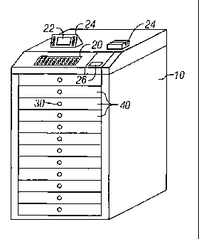
Referring to FIG. 1, a storage means is represented by the general reference
number 10.
The storage means 10 has at least one drawer, or more preferably, a plurality
of drawers 40. The
storage means 10 has an input means 20 for entering access data, and a lock 30
associated with the
input means 20 and capable of being selectively locked and unlocked upon the
entry of access data
(not shown). According to FIG. 1, the input means 20 is represent by a
keyboard, but can by of
any known input technology such as a touch screen 22 as part of a display
monitor 24, a coded
CA 02449399 2003-12-03
WO 02/099231
PCT/US02/21239
card reader 26, a magnetic strip reader 28, or any other technologies
previously described or 7
known in the art.
The present method also provides that the storage means selectively limits
access to a
wireless unlocking means 100, which is shown in FIG. 2, that is removably
secured within the
storage means 10. In another embodiment, the wireless unlocking means is
permanently secured
or even integrated into the storage means (not shown). In a particular
embodiment, the wireless
unlocking means 100 would be adapted with a display screen 102, which would
depict any desired
information, including but not limited to: the access data, patient account
information, inventory
information, and the like. The wireless unlocking means could also be adapted
with a keypad 104,
which could be coupled with the storage means 10 to allow the entry of
supplemental access data
to access additional drawers in the plurality 40, or to enter any desired
information into the storage
means 10 for recording same in the recording means, if so equipped (not
shown).
The wireless unlocking means 100 is wirelessly coupled to the locking system
210 of the
secondary storage location 200, which is shown in FIG. 3. The secondary
storage location 200
includes a door 220. According to a preferred embodiment, the secondary
storage location 200 is
a refrigerator of any conventional type equipped to cool its contents below
ambient temperature.
The door 220 of the secondary storage location 200 is adapted with a handle
230 for easy opening
when the locking system 210 is unlocked. The present invention contemplates
that the interior
area (not shown) of the secondary storage location 200 may be a single storage
location in which
one or more types inventoried items (not shown) are housed. Alternatively the
interior area may be
divided into several storage locations. These storage locations may be open
storage locations or
may be subcompatiments to which access is further controlled by electronic or
other types of
locking mechanisms (not shown). Access to the interior area is controlled by
the unlocking signal
(not shown) transmitted by the wireless unlocking means 100. Preferably, the
locking system 210,
receives the unlocking signal at a sensor 240. The unlocking signal is
preferably an infrared
wavelength or a radio frequency, depending on whether the user requires line
of sight operation.
The locking system 210 unlocks when the appropriate unlocking signal is
received from the
wireless unlocking means 100. The locking system 210 also includes at least
one visual indicator
250, which is preferably an LED type indicator. The visual indicator 250
illuminates when the
locking system 210 is unlocked. In alternative embodiments, an additional
visual indicator (not
shown) would illuminate when the sensor 240 was receiving the unlocking signal
from the
wireless unlocking means, or when the power source (not shown) of the locking
system was
operative. In alternative embodiments other types of indicators or additional
indicators may be
used. Preferably, the power source of the locking mechanism is an alternating
current or a battery,
= CA 02449399 2012-04-24
or a combination thereof, the strength of which could be depicted on the
display screen 102 of the
wireless unlocking means. The locking system 210 also includes an override
system 260 as part
of a manual unlocking mechanism that enables opening the door 220 preferably
using a key (not
shown). Preferably, a manually operated latch (not shown) operates in parallel
with the locking
s system 210 and causes the locking system 210 to relock without further
user activation after it has
first been unlocked.
After the locking system 210 receives the appropriate unlocking signal from
the wireless
unlocking means 100, the locking system unlocks and allows the user to access
the contents of the
secondary storage location 200, which includes at least one inventoried item
(not shown). In one
embodiment of the method, the storage means is equipped with a recording means
to record the
access data the led to the subsequent removal of the inventoried item, as well
as the removal itself.
The present method contemplates that any information associated with the
removal of an
inventoried item could be recorded for subsequent retrieval or subsequent
incorporation into
additional inventory or accounting methods or systems.
While specific embodiments have been illustrated and described, numerous
modifications are possible, and the scope of protection is only limited by the
scope of the
accompanying claims.
=
=