Note : Les descriptions sont présentées dans la langue officielle dans laquelle elles ont été soumises.
CA 02451732 2003-12-01
SEED PLACEMENT SYSTEM FOR USE IN A SEEDING MACHINE
Field of the Invention
The present invention relates to agricuitural seeding machines, and, more
particularly, to seed placement systems used to place seeds along a desired
path
and at a desired spacing within a seed trench.
Background of the Invention
An agricultural seeding machine such as a row crop planter or grain drill
places seeds at a desired depth within a plurality of parallel seed trenches
formed in
soil. In the case of a row crop planter, a plurality of row crop units are
typically
ground driven using wheels, shafts, sprockets, transfer cases, chains and the
like.
Each row crop unit has a frame which is moveably coupled with a tool bar. The
frame may carry a main seed hopper, herbicide hopper and insecticide hopper.
If a
granular herbicide and insecticide are used, the metering mechanisms
associated
with dispensing the granular product into the seed trench are relatively
simple. On
the other hand, the mechanisms necessary to properly meter the seeds, dispense
the seeds at a predetermined rate and place the seeds at predetermined
relative
locations within the seed trench are relatively complicated.
The mechanisms associated with metering and placing the seeds generally
can be divided into a seed metering system and a seed placement system which
are
in communication with each other. The seed metering system receives the seeds
in
a bulk manner from the seed hopper carried by the frame. Different types of
seed
metering systems may be used such as seed plates, finger plates, and seed
discs.
In the case of a seed disc metering system, a seed disc is formed with a
plurality of
seed cells spaced about the periphery thereof. Seeds are moved into the seed
cells,
with one or more seeds in each seed cell depending upon the size and
configuration
of the seed cell. A vacuum or positive pressure air may be used in conjunction
with
the seed disc to assist in movement of the seeds into the seed cells. The
seeds are
singulated and discharged at a predetermined rate to the seed placement
system.
With a seed metering system including a seed disc as described above, the
seed disc typically includes a concentric drive shaft having a sprocket on the
CA 02451732 2006-09-06
outboard end which is driven via a ground drive or the like. The
concentrically
positioned driven shaft and sprockets may limit the compactness (i.e.,
reduction in
overall size) of the seed metering system.
The seed placement system may be categorized as a gravity drop system or
a power drop system. In the case of a gravity drop system, a seed tube has an
inlet
end which is positioned below the seed metering system. The singulated seeds
from
the seed metering system merely drop into the seed tube and fall via
gravitational
force from a discharge end thereof into the seed trench. The seed tube may be
curved in a rearward manner to assist in directing seed into the seed trench.
The
rearward curvature also assists in reducing bouncing of the seeds back and
forth
within the tube as it falls therethrough into the seed trench. Further, the
rearward
curvature reduces bouncing of the seed as it strikes the bottom of the seed
trench.
A seed placement system of the power drop variety generally can be
classified as a seed conveyor belt drop, rotary valve drop, chain drop or air
drop.
These types of seed placement systems provide more consistent placement of the
seeds along a predetermined path at a desired spacing. Details of these types
of
seed placement systems, as well as agricultural planting in general, are
available in
the technical document entitled "PLANTING FUNDAMENTALS OF MACHINE
OPERATION"; Breece, Edward H., PhD, et al.; Deere & Co.; 1981.
What is needed in the art is an agricultural seeding machine providing an
accurate, efficient and compact seed metering system and seed placement
system.
Summary of the Invention
The present invention provides a wheel in a seed placement system which
defines a seed meter and accelerator. The wheel has three radial zones,
including a
structural hub, a resilient middle layer surrounding the structural hub, and a
gripping
outside layer surrounding the resilient middle layer. The gripping outside
layer has a
relatively high coefficient of friction to engage and carry without damaging
the seeds.
The invention comprises, in one form thereof, a seeding machine including at
least one seed metering system and at least one seed placement system which is
2
CA 02451732 2003-12-01
in communication with a corresponding seed metering system. Each seed
placement system includes a seed slide and a wheel. The wheel includes a
structural hub, a resilient middle layer positioned radially around the hub,
and a
gripping outside layer positioned radially around the middle layer. The
gripping
outside layer has a circumferential periphery which is positioned adjacent to
at least
part of the seed slide. The circumferential periphery has a plurality of
contiguous
disjoint surfaces.
The invention comprises, in another form thereof, a method of placing seeds
with a seeding machine in a trench formed in soil. Seeds are received at a
predetermined rate at a seed placement system. The seed placement system
includes a seed slide and a wheel. The wheel has a structural hub, a resilient
middle
layer positioned radially around the hub, and a gripping outside layer
positioned
radially around the middle layer. The gripping outside layer has a
circumferential
periphery which is positioned closely adjacent to at least part of the seed
slide. The
circumferential periphery has a plurality of contiguous disjoint surfaces. The
seeds
are engaged at the predetermined rate against the wheel periphery. The seeds
are
carried past at least part of the seed slide with the wheel periphery while
maintaining
the seeds in contact with the seed slide. Orientation and size variations of
the seeds
are accommodated by locally deflecting the resilient middle layer during the
carrying
step. The seeds are released from the wheel periphery to be placed within the
trench.
An advantage of the present invention is that the wheel regulates the seeds
in a positive manner.
Another advantage is that the bristles at the circumferential periphery of the
wheel positively engage the seeds and carry the seeds past the seed slide,
regardless of the size and orientation of the seeds.
Yet another advantage is that the gripping outside layer at the
circumferential periphery of the wheel may take the form of several different
materials having a high coefficient of friction, such as bristles, a foam pad,
an
expanded foam pad, a mesh pad, a fiber pad and a grit layer.
3
CA 02451732 2003-12-01
Brief Description of the Drawings
Fig. 1 is a side view of an embodiment of a seeding machine of the present
invention including a row crop unit;
Fig. 2 is a partially fragmentary, side view of the row crop unit shown in
Fig.
1, illustrating the internal components of the seed metering system and seed
placement system;
Fig. 3 is a perspective view of the seed metering system and seed
placement system shown in Fig, 2, with one of the side plates removed to show
the
wheel and seed slide;
Fig. 4 is a side view of the seed placement system shown in Figs. 2 and 3;
and
Fig. 5 is a sectional view of the wheel shown in Fig. 4, taken along line 5-5.
Detailed Description of the Invention
Referring now to the drawings, and more particularly to Figs. 1 and 2, there
is shown an embodiment of a seeding machine 10 of the present invention. In
the
embodiment shown, seeding machine 10 is in the form of a row crop planter but
may
also be in the form of a grain drill, etc. Figs. 1 and 2 illustrate a single
row crop unit
12 of a muiti-row planter, with each row crop unit 12 being substantially
identical and
connected to a common tool bar 14. Only a single row crop unit 12 is shown for
simplicity sake.
Row crop unit 12 includes a multi-part frame 16 which is attached to tool bar
14 by parallel linkage 18. Tool bar 14 is coupled to a traction unit (not
shown), such
as an agricultural tractor. For example, tool bar 14 may be coupled to an
agricultural
tractor using a 3-point hitch assembly. Tool bar 14 may be coupled with
transport
wheel assemblies, marker arms, etc. which may be of conventional design and
not
shown for simplicity sake. The transport wheels, in known manner, may provide
ground drive to row crop unit 12 through the use of shafts, chains, sprockets,
transfer
cases, etc.
Frame 16 carries a double disc furrow opener 20 for forming a seed trench
in soil. A pair of gauge/closing wheels 22 are respectively associated with
the pair of
4
CA 02451732 2003-12-01
discs of double disc furrow opener 20. More particularly, each gauge/closing
wheel
22 is positioned generally in line with and immediately adjacent to the
outside of
each respective disc of double disc furrow opener 20. Gauge/closing wheels 22
are
pivotally coupled with frame 16 by respective arms 24. Each gauge/closing
wheels
26 may be vertically adjusted to adjust the depth of the trench which is cut
into the
soil using double disc furrow opener 20.
A pair of closing wheels 26 are also carried by frame 16. Closing wheels 26
are positioned generally in line with double disc furrow opener 20.
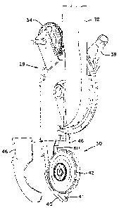
Referring now to Fig. 2, each row crop unit 12 of seeding machine 10 carries
a seed metering system 28 and a seed placement system 30. Seed metering
system 28 includes an inlet chute 32 which receives seed from a main seed
supply,
such as a seed hopper carried above frame 16. Alternatively, seed may be
stored in
a distant main seed hopper and supplied to inlet chute 32 via air or the like.
Seed metering system 28 also includes a drive wheel 34 which drives a
seed disc 36 having a plurality of seed cells 38 intermittently spaced about
the
periphery thereof. A coupler 39 is fluidly coupled with a vacuum source (not
shown)
for applying vacuum pressure to seed cells 38 formed in seed disc 36. This
vacuum
pressure promotes entry of the seeds into seed cells 38 and maintains the
seeds in
place within seed cells 38. Seeds are transported from seed cells 38 to seed
placement system 30.
Seed placement system 30 includes a seed slide 40 which directs seed at a
predetermined rate into the seed trench formed by double disc furrow opener
20.
Seed slide 40 has a width in a direction transverse to the seed trench which
is less
than the width of the seed trench, but may also be approximately equal to the
width
of the seed trench.
Wheel 42 defining a seed velocity regulator has a circumferential periphery
which is positioned at or closely adjacent to seed slide 40. Wheel 42 engages
the
seeds received at seed placement system 30 at the predetermined rate and
regulates the seeds to a speed substantially corresponding to the traveling
speed of
seeding machine 10 in travel direction 44. Wheel 42 and seed slide 40 co-act
to
discharge the seeds at a desired trajectory and velocity.
CA 02451732 2003-12-01
Side plates 46 attach to seed slide 40 and are positioned on either side of
wheel 42. Side plates 46 and seed slide 40 together define a housing which
partialiy
surrounds wheel 42.
Referring now to Figs. 4 and 5, seed placement system 30 will be described
in greater detail. Wheel 42 defines a seed regulator which, together with seed
slide
40, discharges seeds at a pre-determined rate from a bottom end 48 of seed
slide
40. Wheel 42 generally includes a structural hub 50, a resilient middle layer
52 and
a gripping outside layer 54. A driven sprocket 56 is ground driven via a chain
(not
shown) using suitable ground drive structure on the seeding machine.
Alternatively,
sprocket 56 may be driven using a hydraulic motor, electric motor, etc.
Sprocket 56
is driven at a rotational speed causing a tangential velocity at the outside
diameter of
wheel 42 to generally match the forward speed of the seeding machine. Of
course,
wheel 42 may be driven at a different rotational speed depending upon the
particular
application.
Structural hub 50 is constructed of a suitable plastic providing structural
support to wheel 52. The particular type of plastic which is used is selected
to
provide enough rigidity so that structural hub 50 is not deflected during
normal use.
Structural hub 50 may also be constructed from a different type of material
such as
metal or a composite, depending on the particular application. Structural hub
50 is
generally disc shaped and provides structural support to each of resilient
middle
layer 52 and gripping outside layer 54.
Resilient middle layer 52 is positioned radially around structural hub 50.
Resilient middle layer 52 has a generally rectangular cross-sectional
configuration as
shown in Fig. 5. Resilient middle layer 52 is constructed from a material
allowing
limited radially inward deflection to accommodate various sizes and
orientations of
seeds which pass between wheel 42 and seed slide 40. In the embodiment shown,
resilient middle layer 52 is constructed from high density polyurethane foam
having a
density of between 15-20 pounds per cubic foot. This density of foam is
believed to
correspond to a shore durometer hardness rating of approximately 12 (shore 0).
Foam having a shore durometer hardness rating of between 20-70 durometer may
be used, depending on the particular application. Additionally, resilient
middle layer
6
CA 02451732 2003-12-01
52 may be formed from rubber, expanded foam or other similar type resilient
material.
Gripping outside layer 54 is positioned radially around resilient middle layer
52. Gripping outside layer 54 has a circumferential periphery defining an
outside
diameter of wheel 42. The circumferential periphery of gripping outside layer
54 is
positioned closely adjacent to a portion of seed siide 40. More particularly,
the
circumferential periphery of gripping outside layer 54 is positioned at a
distance of
between 0 to 5 millimeters from a portion of seed slide 40. In the embodiment
shown, the circumferential periphery of gripping outside layer 54 is
positioned a
distance of approximately 1 millimeter from seed slide 40.
Gripping outside layer 54 is formed with a circumferential periphery which
has a plurality of contiguous disjoint surfaces. Regardless of the particular
type of
contiguous disjoint surface utilized, as will be described in more detail
hereinafter, a
high co-efficient of friction is provided which grips the seeds and carries
the seeds at
the pre-determined rate through the area between wheel 42 and seed slide 40
without excessively damaging the seeds. In the embodiment shown in Figs. 4 and
5,
the plurality of contiguous disjoint surfaces are in the form of a nylon
bristle material
made by 3M Corporation. The bristles are approximately 0.003 inch in diameter
and
approximately 1/8 inch in length. Depending upon the particular application,
the
material type, bristles length and bristle diameter may vary. For example, the
bristles may range up to approximately one inch in length and up to
approximately
0.024 inch in diameter. Furthermore, other types of materials having a high
coefficient of friction may also be used such as a foam pad, expanded foam
pad,
mesh pad, fiber pad or a grit layer.
Seed slide 40 is formed with a seed trough 41 which increases in depth from
top end 49 to bottom end 48. Seed trough 41 keeps the seed centered on seed
slide
40 as it is carried by wheel 42 and also improves the trajectory at which the
seed is
discharged from bottom end 48 into the seed trench formed in the soil.
A deflector 60 is positioned below a discharge chute 58 extending from the
bottom of seed metering system 28 towards seed placement system 30. Deflector
60 guides the seeds into the nip formed between wheel 42 and seed slide 40.
7
CA 02451732 2003-12-01
Deflector 60 may also be configured to contact the plurality of bristles at
gripping
outside layer 54 of wheel 42. This local deflection of the bristles assists in
positively
moving the seed into the nip between wheel 42 and seed slide 40. In the
embodiment shown, deflector 60 is in the form of a plate having a width
corresponding to the width of wheel 42. However, deflector 60 may be
differently
configured.
During use, a selected seed type is received from a main seed supply at
inlet chute 32 of seed metering system 28. The seed is maintained against a
side of
seed disc 36, which is driven by drive wheel 34 at a selected rotational speed
using
a mechanical drive, hydraulic motor, electric motor or other suitable drive.
Seeds are
received within seed cells 38 of seed disc 36. To assist seed movement into
seed
cells 38, a vacuum pressure is applied to the opposite side of seed disc 36
using a
suitable vacuum source. Of course, a positive pressure may also be applied to
the
side of seed disc 36 at which the seeds are disposed. The seeds are discharged
from seed metering system 28 at a predetermined rate through discharge chute
58.
Deflector 60 assists in guiding the seeds into the nip area formed between
wheel 42
and seed slide 40. Deflector 60 may also locally deflect the bristles of
gripping
outside layer 54 as it rotates therepast. Deflection of the bristles assists
in gripping
the seeds and carrying the seeds into the nip adjacent seed slide 40. The gap
of
approximately one millimeter between the circumferential periphery of wheel 42
and
seed slide 40 ensures that the seed is gripped by gripping outside layer 54
without
applying too much force against the seed. Resilient middle layer 52 also may
be
compressed depending upon the seed size and/or orientation as it travels in
the area
between wheel 42 and seed slide 40. Seed trough 41 continually increases in
depth
and maintains the seeds along the longitudinal axis of seed slide 40. The seed
is
regulated to approximately match the ground speed of the seeding machine and
is
discharged from seed trough 41 at bottom end 48 into the seed trench formed in
the
soil. Gauge/closing wheels 22 and closing wheels 26 close the seed trench and
thereby cover the seed in the trench.
Having described the preferred embodiment, it will become apparent that
various modifications can be made without departing from the scope of the
invention
8
CA 02451732 2003-12-01
as defined in the accompanying claims.
9