Sélection de la langue

Search

Sommaire du brevet 2452336 

Énoncé de désistement de responsabilité concernant l'information provenant de tiers

Une partie des informations de ce site Web a été fournie par des sources externes. Le gouvernement du Canada n'assume aucune responsabilité concernant la précision, l'actualité ou la fiabilité des informations fournies par les sources externes. Les utilisateurs qui désirent employer cette information devraient consulter directement la source des informations. Le contenu fourni par les sources externes n'est pas assujetti aux exigences sur les langues officielles, la protection des renseignements personnels et l'accessibilité.

Disponibilité de l'Abrégé et des Revendications

L'apparition de différences dans le texte et l'image des Revendications et de l'Abrégé dépend du moment auquel le document est publié. Les textes des Revendications et de l'Abrégé sont affichés :

  • lorsque la demande peut être examinée par le public;
  • lorsque le brevet est émis (délivrance).
(12) Brevet: (11) CA 2452336
(54) Titre français: BOBINEUSE A BANDE MINCE MUNIE D'UN ROULEAU DE MESURE DE PLANEITE
(54) Titre anglais: THIN-STRIP COILER COMPRISING A FLATNESS MEASURING ROLL
Statut: Périmé et au-delà du délai pour l’annulation
Données bibliographiques
(51) Classification internationale des brevets (CIB):
  • G01B 05/28 (2006.01)
  • B21B 15/00 (2006.01)
  • B21B 38/02 (2006.01)
  • B21B 39/12 (2006.01)
  • B21C 47/06 (2006.01)
  • B21C 51/00 (2006.01)
  • G01B 21/30 (2006.01)
(72) Inventeurs :
  • BRAUN, MARTIN (Allemagne)
  • ARMENAT, JURGEN (Allemagne)
  • GROSSHARDT, KLAUS-JURGEN (Allemagne)
(73) Titulaires :
  • SMS SIEMAG AKTIENGESELLSCHAFT
(71) Demandeurs :
  • SMS SIEMAG AKTIENGESELLSCHAFT (Allemagne)
(74) Agent: SMART & BIGGAR LP
(74) Co-agent:
(45) Délivré: 2010-02-16
(86) Date de dépôt PCT: 2002-06-11
(87) Mise à la disponibilité du public: 2003-01-16
Requête d'examen: 2007-04-20
Licence disponible: S.O.
Cédé au domaine public: S.O.
(25) Langue des documents déposés: Anglais

Traité de coopération en matière de brevets (PCT): Oui
(86) Numéro de la demande PCT: PCT/EP2002/006358
(87) Numéro de publication internationale PCT: EP2002006358
(85) Entrée nationale: 2003-12-29

(30) Données de priorité de la demande:
Numéro de la demande Pays / territoire Date
101 31 850.2 (Allemagne) 2001-06-30

Abrégés

Abrégé français

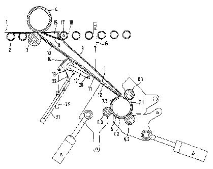
L'invention concerne un procédé et un dispositif permettant de mesurer et d'influer sur la planéité dans le puits de bobineuse d'un système pour laminer les feuillards chauds, ledit puits de bobineuse présentant entre un élément d'entraînement et une bobineuse, des guides de bande mobiles et fixes, ainsi qu'un rouleau de mesure de planéité (13). Le feuillard chaud (1) est acheminé par l'intermédiaire d'une ligne de rouleaux (2) et des rouleaux d'entraînement (3, 4) de l'élément d'entraînement, à travers le puits de bobineuse, jusqu'à une bobineuse comportant un mandrin (5), des rouleaux de compression (6) et des coques de renvoi (7). Le rouleau de mesure de planéité (13) passe d'une position de travail dans laquelle le feuillard chaud est guidé autour du rouleau de mesure de planéité (13), un angle d'enroulement alpha approximativement constant étant maintenu, dans une position inclinée. Il est prévu dans le puits de bobineuse un guide de bande (14) pivotant protégeant le rouleau de mesure de planéité (13).


Abrégé anglais


The invention relates to a method and device for measuring and influencing the
strip flatness in
the coiler shaft of a hot-strip mill, whereby the coiler shaft has, between a
driver and a coiler,
moving and stationary strip guides as well as a flatness measuring roll (13).
The hot strip (1) is
supplied via the coiler shaft to a coiler, which is provided with a coiler
mandrel (5), pressure
rolls (6) and with deflecting shells (7), over a roller table (2) and the
driving rolls (3, 4) of the
driver. The flatness measuring roll (13) is displaced out of a working
position, in which the hot
strip is guided around the flatness measuring roll (13) while maintaining an
approximately
constant contact angle .alpha., and into a lowered position. In addition, a
strip guide (14), which can
swivel inward and protects

Revendications

Note : Les revendications sont présentées dans la langue officielle dans laquelle elles ont été soumises.


Claims
1. Process for measuring and influencing the flatness of
strip in the toiler shaft of a hot strip rolling mill, where the
coiler shaft has movable and stationary strip guides between a
driver and a toiler as well as a flatness measuring roll, which
is moved from a working position, in which the hot strip is
guided around the flatness measuring roll (13) under maintenance
of a nearly constant contact angle .alpha., into a lowered position,
and where the hot strip is sent by way of a roller table and the
driver rolls of the driver through the toiler shaft to a toiler
equipped with coiling mandrel, pressure rolls, and deflecting
shells, characterized in that the flatness measuring roll (13) is
protected in the toiler shaft by a strip guide (14), which can be
swiveled into and out of position.
2. Device on a toiler shaft, which has between a driver and
a coiler movable and stationary strip guides and a flatness
measuring roll which can be moved from a working position, in
which the hot strip can be guided around the flatness measuring
roll (13) under maintenance of a nearly constant contact angle .alpha.,
into a lowered position, and where the hot strip is sent by way
of a roller table and the drive rolls of the driver through the
toiler shaft to the toiler, which is equipped with a coiler
12

mandrel, pressure rolls, and deflecting shells, for implementing
the process according to Claim 1, characterized in that, in the
coiler shaft, a strip guide (14) is provided, which protects the
flatness measuring roll (13) and which can be swiveled into and
out of position.
3. Device according to Claim 2, characterized in that the
flatness measuring roll (13) can be moved into the working
position after the tensile stresses have been built up.
4. Device according to Claim 2 or Claim 3, characterized in
that the flatness measuring roll (13) is attached to a swiveling
frame (19), which is rotatably supported at a center of rotation
(20).
5. Device according to one of Claims 2-4, characterized in
that the flatness measuring roll (13) can be moved around the
center of rotation (20) into the working position by a hydraulic
cylinder (21).
13

6. Device according to one of Claims 2-5, characterized in
that the flatness measuring roll (13) can be rotated by a drive.
7. Device according to Claim 6, characterized in that both
the rotational speed and the torque of the drive can be
automatically controlled in a continuously variable manner.
8. Device according to one of Claims 2-7, characterized in
that the flatness measuring roll (13) and the strip guide (14)
can be moved separately from each other around different centers
of rotation (20, 22).
9. Device according to one of Claims 2-8, characterized in
that the flatness measuring roll (13) can be moved in a
continuously variable manner as far as the stop on the cylinder
(21) and can be repositioned to accommodate the changing height
of the coil so that a nearly constant contact angle a can be
maintained.
10. Device according to one of Claims 2-9, characterized
in that the strip guide (14) can be moved by the hydraulic
cylinder (23) around the center of rotation (22).
11. Device according to one of Claims 2-7, characterized
in that the flatness measuring roll (13) and the strip guide
(14) can be moved around a common center of rotation (20).
14

12. Device according to Claim 11, characterized in that
the flatness measuring roll (13) and the strip guide (14) can be
mounted on a support frame (19).
13. Device according to Claims 11 and 12, characterized in
that the flatness measuring roll (13) can be swiveled into a
stationary working position.
14. Device according to one of Claims 11-13, characterized
in that the position-controlled deflecting roll (24) can be
introduced into the tension path of the hot strip (1) to
maintain a nearly constant contact angle a around the flatness
measuring roll (13).
15. Device according to Claim 14, characterized in that
the deflecting roll (24) can be rotated by a drive, the
rotational speed and/or the torque of which can be controlled in
a continuously variable manner.

Description

Note : Les descriptions sont présentées dans la langue officielle dans laquelle elles ont été soumises.


CA 02452336 2003-12-29
TRANSLATION (HM-546PCT):WO 03/004,963 A1
PCT/EP02/06,358
THIN-STRIP COILER COMPRISTNG A FLATNESS MEASURING ROLL
The invention pertains to a process for measuring and
influencing the flatness of strip material in the toiler shaft of
a hot-strip mill, where the toiler shaft has movable and
stationary strip guides between a driver and a toiler and also a
flatness measuring roll which is moved from a work position in
which the hot strip is guided around the flatness measuring roll
while maintaining an essentially constant angle a of contact,
into a lowered position, and where the hot strip is sent by way
of a roller table and the drive rolls of the driver through the
toiler shaft to a~coiler equipped with a coiling mandrel,
pressure rolls, and deflecting shells. The invention also
pertains to a device for implementing the process.
In cold-rolling mills, it is known that flatness measuring
rolls can be used to control the screw-down settings and
adjustments of the stands so that a rolled strip free of stresses
can be obtained. For example, the rolling force of one stand can
be made different from that of the next, and/or corrective
measures can be carried out by means of the existing adjusting
systems (e. g., bending, hydraulic screw-down, roll cooling,
etc.). In modern hot-rolling processes, strips are rolled to a
1

CA 02452336 2003-12-29
minimum thickness of < 1.0 mm. The flatness of the strip is very
important in the production of thin, hot-rolled strip and imposes
strict requirements on the various components of the system_ The
various devices downline from the rolling stands, such as the
strip cooling unit, the roller table with roll cooling, and the
driver in front of the coiler also affect the flatness of the
strip.
The idea of measuring flatness by means of a flatness
measuring roll offers advantages when the final strip is to have
a thickness of approximately 3 mm or less, because the previously
used optical measuring system units eventually encounter their
limits as the final thickness of the strip decreases and the
runout velocities increase.
The disadvantage here, however, is that the flatness
measuring roll is attached to the end of the roller table, and
thus any factors which influence the flatness of the strip
downstream from this point are not taken into account.
An arrangement for measuring the flatness of a rolled strip
in a hat-rolling mill with a blooming train and a finishing train
with several rolling stands and a coiler is known from DE 197 04
447 A1, where one or more measuring rolls are installed between,
2

CA 02452336 2003-12-29
for example, the driver apparatus and the toiler. One or more
measuring rolls are provided in the toiler shaft, but negative
strip running properties are observed, usually at the beginning
and end of the strip.
WO 00/41823 of the generic type discloses a raisable and
lawerable flatness measuring roll in a toiler shaft which when it
is made inoperative is replaced by roller table rollers.
Protection of the flatness measuring roll against contamination
and heat is not ensured in this position. Because of the
complicated roller table rollers, the arrangement is very
expensive.
WO 01/51227 discloses a similar flatness measuring roll
which, however, is not arranged in the toiler shaft. In addition
to the roller table rollers, this flatness measuring roll has an
additional protective plate which makes the arrangement even more
expensive.
The invention is based on the task of further developing the
generic flatness measuring roll arrangement in such a way that it
can be manufactured very advantageously and additionally provides
an effective protection for the flatness measuring roll in the
lowered position.
3

CA 02452336 2003-12-29
In a process and in a device of the type indicated above,
this task is accomplished by the features of Process Claim 1 and
by the features of Device Claim 2. Advantageous embodiments of
the invention and various elaborations of the device are
disclosed in the subclaims.
The basic idea of the invention is to provide a process and
a device for measuring and influencing the flatness of the strip,
where the flatness measuring roll is moved out of a working
position, in which the hot strip is guided around the flatness
measuring roll under maintenance of a more-or-less constant
contact angle, into a lowered position, and in that the flatness
measuring roll is protected in the coiler shaft by a strip guide,
which can be swiveled into and out of position.
3a

CA 02452336 2003-12-29
As a result of this measure, the flatness measuring roll can be
moved into a protected position, preferably at both the
beginning and at the end of the strip. A strip guide which has
swiveled inward to protect the flatness measuring roll is
installed in the toiler shaft, as a result of which the strip
can be made to run more reliably, especially at the beginning
and end of the strip.
Additional details and advantages of the invention can be
derived from the following description, which explains in
greater detail the exemplary embodiments of the invention
illustrated in the drawings:
-- Figure 1 shows a flatness measuring roll, installed
between the driver and the toiler, during the infeed of the
beginning of the strip;
-- Figure 2 shows a flatness measuring roll in the
measuring position just after the start of coiling;
-- Figure 3 shows a flatness measuring roll in a later
measuring position during the winding of the coil;
-- Figure 4 shows a flatness measuring roll, still in the
measuring position, just before the end of the coiling process;
-- Figure 5 shows a flatness measuring roll in the lowered
4

CA 02452336 2003-12-29
position during the entrance of the strip;
-- Figure 6 shows a different arrangement with a flatness
measuring roll and a deflection roll between the driver and the
toiler during the infeed of the beginning of the strip;
-- Figure 7 shows a flatness measuring roll according to
Figure 6 in the measuring position after the deflection roll has
been lowered shortly after the start of coiling;
-- Figure 8 shows a flatness measuring roll according to
Figure 6 in the measuring position after the deflection roll has
been lowered and shortly before the end of the coiling process;
and
-- Figure 9 shows a flatness measuring roll according to
Figure 6 in the lowered position and a deflection roll in the
raised position during the outfeed of the end of the strip.
A hot strip 1 is sent via a roller table 2 to the drive
rolls 3 and 4 of a driver and from there to a toiler, which is
equipped with a coiling mandrel 5, pressure rolls 6, and
deflecting shells 7. Strip guides 8, 9, 10, 11, 12; a flatness
measuring roll 13; and a swiveling protective device 14 are
installed between the driver and the toiler. The strip guide 8
is a part of a strip distributing guide 15 for redirecting the

CA 02452336 2003-12-29
beginning of the strip as desired in cases where multiple
coilers are being used.
The strip guide 9 is a shaft flap 9, actuated by means of,
for example, a cylinder 16; immediately after the entrance of
the strip, this flap is swiveled upward around the center of
rotation 17, which is shared in common by the strip distributing
guide 15, the shaft flap 9, and the distributing guide roll 18.
The strip guide 10 is a stationary guide, which can be
adjusted only with respect to the gap between it and the drive
roll 3.
The strip guide 11 is also stationary, whereas the strip
guide 12, which is connected to the deflecting shell 7.3, is
swiveled away together with the shell and the pressure roll 6.3
after the strip has entered.
The flatness measuring roll 13 is supported in a swiveling
frame 19, which turns around a stationary center of rotation 20
and can be swiveled by, for example, an automatically position-
controlled hydraulic cylinder 21.
An actual-value position sensor, which can be mounted
either in the hydraulic cylinder 21 or at the center of rotation
20, records the actual position of the swiveling frame 19, i.e.,
6

CA 02452336 2003-12-29
of the flatness measuring roll 13.
The swiveling protective device 14 can swivel around the
stationary center of rotation 22 under the action of, for
example, a cylinder 23. This protective device 14 serves both
the guide the strip during the entrance of the strip and also to
protect the measuring roll 13 when it is in the lowered
position.
The flatness measuring roll 13 is equipped with a rotary
drive (not shown), both the rotational speed and torque of which
are automatically controlled, so that, when the roll is in
contact with the strip, there will be no relative velocity
between the strip 1 and the surface of the roll, and no scorings
or material deposits will form. As a result, it is possible to
begin the flatness measurement as soon as contact with the strip
has been established.
After the start of coiling, the flatness measuring roll 13
is swiveled into its starting position (compare Figure 2); this
position is then continuously readjusted in correspondence with
the increase in the diameter of the coil under preservation of a
constant contact angle a.
Shortly before the end of the coiling process, the flatness
7

CA 02452336 2003-12-29
measuring roll 13 is lowered, and the strip guide 14, which also
serves to protect the flatness measuring roll 13, is swiveled
back into position.
Simultaneously with the lowering of the flatness measuring
roll 13, the pressure rolls 6 are moved up to the coil to
prevent the outer turns from expanding outward.
After the coil has been removed, the pressure rolls 6 and
the deflecting shells 7 are swiveled back into the starting
position according to Figure 1, and the shaft flap 9 is lowered.
It is now possible for a new strip to be coiled.
Another variant of the device is shown in Figures 6-9 and
described below. A hot-rolled strip 1 is sent via a roller
table 2 and the drive rolls 3, 4 of a driver to a coiler, which
is equipped with a coiling mandrel 5, pressure rolls 6, and
deflecting shells 7.
Strip guides 8, 9.1, 9.2, 10, 11, 12; a flatness measuring
roll 13 with a swiveling strip guide 14; and a deflection roll
24 are installed between the driver the coiler.
The strip guide 8 is part of a strip distributing guide 15,
which makes it possible to switch the beginning of the strip
from one coiler to another in cases where multiple coilers are
8

CA 02452336 2003-12-29
being used.
The strip guide 9.1, 9.2 represents the shaft flap 9.1,
9.2, which is actuated by means of, for example, two position-
controlled hydraulic cylinders 16, 25, and which is pivotably
supported at a center of rotation 17, which is shared in common
by the strip distributing guide 15, the distributing guide roll
18, and the shaft flap 9.1, 9.2.
The deflecting roll 24 is supported rotatably on the shaft
flap 9.1, which swivels around the center of rotation 17; after
the beginning of the strip has arrived and the coiling operation
has begun, the deflecting roll is lowered into position against
stationary stops in a position-controlled manner. During this
lowering movement of the deflecting roll 24, the separately
swiveling part 9.2 of the shaft flap is simultaneously swiveled
upward by means of the cylinder 25 around the center point 26 of
the deflecting roll 24, so that the necessary space is created
for the coil to be wound up.
Immediately after the coiling has begun, the flatness
measuring roll 13, which is supported in a swivel frame 19, is
swiveled around the center of rotation 20 by means of, for
example, a position-controlled hydraulic cylinder 21 against two
9

CA 02452336 2003-12-29
stationary stops and thus into the measuring position.
In this measuring position, the geometry of the traveling
strip between the driver roll 3, the flatness measuring roll 13
with a constant contact angle a, and the deflecting roll 24
remains constant throughout the entire coiling process.
The strip guide 14 is attached to the swiveling frame 19 of
the flatness measuring roll 13 and is swiveled away
automatically when the flatness measuring roll 13 is swung away.
Just before the end of the strip arrives, the shaft flap
9.1 is swiveled along with the deflecting roll 24 into the upper
end position, while simultaneously the flap 9.2 is lowered; the
flatness measuring roll 13 is moved into its lowered, protected
position.
After the coil has been removed, the pressure rolls 6 are
swiveled along with the deflecting shells 7 back into the
initial coiling position according to Figure 6, and the shaft
flap 9.1, 9.2 is also lowered along with the deflecting roll 24
into the initial coiling position according to Figure 6. Then a
new strip can be coiled.
The flatness measuring roll 13 and the deflecting roll 24
are equipped with rotary drives (not shown), both the speed and

CA 02452336 2003-12-29
torque of which are automatically controlled, so that there are
no relative velocities between the strip and the roll surface,
and no scorings or material deposits are formed. This means
that the flatness measurement can be begin as soon as contact
with the strip has been established.
11

Dessin représentatif
Une figure unique qui représente un dessin illustrant l'invention.
États administratifs

2024-08-01 : Dans le cadre de la transition vers les Brevets de nouvelle génération (BNG), la base de données sur les brevets canadiens (BDBC) contient désormais un Historique d'événement plus détaillé, qui reproduit le Journal des événements de notre nouvelle solution interne.

Veuillez noter que les événements débutant par « Inactive : » se réfèrent à des événements qui ne sont plus utilisés dans notre nouvelle solution interne.

Pour une meilleure compréhension de l'état de la demande ou brevet qui figure sur cette page, la rubrique Mise en garde , et les descriptions de Brevet , Historique d'événement , Taxes périodiques et Historique des paiements devraient être consultées.

Historique d'événement

Description Date
Le délai pour l'annulation est expiré 2015-06-11
Lettre envoyée 2014-06-11
Accordé par délivrance 2010-02-16
Inactive : Page couverture publiée 2010-02-15
Préoctroi 2009-12-04
Inactive : Taxe finale reçue 2009-12-04
Lettre envoyée 2009-09-29
Un avis d'acceptation est envoyé 2009-06-05
Lettre envoyée 2009-06-05
Un avis d'acceptation est envoyé 2009-06-05
Inactive : Approuvée aux fins d'acceptation (AFA) 2009-06-02
Modification reçue - modification volontaire 2007-05-16
Lettre envoyée 2007-05-15
Requête d'examen reçue 2007-04-20
Toutes les exigences pour l'examen - jugée conforme 2007-04-20
Exigences pour une requête d'examen - jugée conforme 2007-04-20
Inactive : CIB de MCD 2006-03-12
Lettre envoyée 2005-03-09
Inactive : Correspondance - Transfert 2005-01-11
Inactive : Correspondance - Transfert 2004-12-23
Inactive : Lettre officielle 2004-06-02
Inactive : IPRP reçu 2004-05-26
Inactive : Transfert individuel 2004-04-29
Inactive : Lettre de courtoisie - Preuve 2004-03-02
Inactive : Page couverture publiée 2004-03-01
Inactive : CIB en 1re position 2004-02-26
Inactive : Notice - Entrée phase nat. - Pas de RE 2004-02-26
Demande reçue - PCT 2004-01-27
Exigences pour l'entrée dans la phase nationale - jugée conforme 2003-12-29
Demande publiée (accessible au public) 2003-01-16

Historique d'abandonnement

Il n'y a pas d'historique d'abandonnement

Taxes périodiques

Le dernier paiement a été reçu le 2009-05-21

Avis : Si le paiement en totalité n'a pas été reçu au plus tard à la date indiquée, une taxe supplémentaire peut être imposée, soit une des taxes suivantes :

  • taxe de rétablissement ;
  • taxe pour paiement en souffrance ; ou
  • taxe additionnelle pour le renversement d'une péremption réputée.

Les taxes sur les brevets sont ajustées au 1er janvier de chaque année. Les montants ci-dessus sont les montants actuels s'ils sont reçus au plus tard le 31 décembre de l'année en cours.
Veuillez vous référer à la page web des taxes sur les brevets de l'OPIC pour voir tous les montants actuels des taxes.

Titulaires au dossier

Les titulaires actuels et antérieures au dossier sont affichés en ordre alphabétique.

Titulaires actuels au dossier
SMS SIEMAG AKTIENGESELLSCHAFT
Titulaires antérieures au dossier
JURGEN ARMENAT
KLAUS-JURGEN GROSSHARDT
MARTIN BRAUN
Les propriétaires antérieurs qui ne figurent pas dans la liste des « Propriétaires au dossier » apparaîtront dans d'autres documents au dossier.
Documents

Pour visionner les fichiers sélectionnés, entrer le code reCAPTCHA :


Pour visualiser une image, cliquer sur un lien dans la colonne description du document. Pour télécharger l'image (les images), cliquer l'une ou plusieurs cases à cocher dans la première colonne et ensuite cliquer sur le bouton "Télécharger sélection en format PDF (archive Zip)" ou le bouton "Télécharger sélection (en un fichier PDF fusionné)".

Liste des documents de brevet publiés et non publiés sur la BDBC .

Si vous avez des difficultés à accéder au contenu, veuillez communiquer avec le Centre de services à la clientèle au 1-866-997-1936, ou envoyer un courriel au Centre de service à la clientèle de l'OPIC.


Description du
Document 
Date
(aaaa-mm-jj) 
Nombre de pages   Taille de l'image (Ko) 
Description 2003-12-28 12 385
Revendications 2003-12-28 4 124
Abrégé 2003-12-28 1 21
Dessins 2003-12-28 9 308
Dessin représentatif 2004-02-29 1 16
Abrégé 2009-06-04 1 21
Rappel de taxe de maintien due 2004-02-25 1 107
Avis d'entree dans la phase nationale 2004-02-25 1 190
Demande de preuve ou de transfert manquant 2004-12-29 1 101
Courtoisie - Certificat d'enregistrement (document(s) connexe(s)) 2005-03-08 1 105
Rappel - requête d'examen 2007-02-12 1 116
Accusé de réception de la requête d'examen 2007-05-14 1 176
Avis du commissaire - Demande jugée acceptable 2009-06-04 1 162
Avis concernant la taxe de maintien 2014-07-22 1 172
PCT 2003-12-28 12 477
Correspondance 2004-02-25 1 24
PCT 2003-12-29 6 225
Correspondance 2004-06-01 1 25
Taxes 2007-06-04 1 36
Correspondance 2009-12-03 1 38