Sélection de la langue

Search

Sommaire du brevet 2459062 

Énoncé de désistement de responsabilité concernant l'information provenant de tiers

Une partie des informations de ce site Web a été fournie par des sources externes. Le gouvernement du Canada n'assume aucune responsabilité concernant la précision, l'actualité ou la fiabilité des informations fournies par les sources externes. Les utilisateurs qui désirent employer cette information devraient consulter directement la source des informations. Le contenu fourni par les sources externes n'est pas assujetti aux exigences sur les langues officielles, la protection des renseignements personnels et l'accessibilité.

Disponibilité de l'Abrégé et des Revendications

L'apparition de différences dans le texte et l'image des Revendications et de l'Abrégé dépend du moment auquel le document est publié. Les textes des Revendications et de l'Abrégé sont affichés :

  • lorsque la demande peut être examinée par le public;
  • lorsque le brevet est émis (délivrance).
(12) Demande de brevet: (11) CA 2459062
(54) Titre français: DISPOSITIF DE FILTRAGE POUR PLAN D'EAU DE JARDIN OU ANALOGUE
(54) Titre anglais: FILTER DEVICE FOR GARDEN PONDS OR SIMILAR
Statut: Réputée abandonnée et au-delà du délai pour le rétablissement - en attente de la réponse à l’avis de communication rejetée
Données bibliographiques
(51) Classification internationale des brevets (CIB):
  • B01D 29/66 (2006.01)
  • B01D 24/00 (2006.01)
  • B01D 24/46 (2006.01)
  • B01D 29/15 (2006.01)
(72) Inventeurs :
  • HOFFMEIER, DIETER (Allemagne)
(73) Titulaires :
  • OASE WUEBKER GMBH & CO. KG.
(71) Demandeurs :
  • OASE WUEBKER GMBH & CO. KG. (Allemagne)
(74) Agent: SMART & BIGGAR LP
(74) Co-agent:
(45) Délivré:
(86) Date de dépôt PCT: 2002-08-28
(87) Mise à la disponibilité du public: 2003-03-27
Requête d'examen: 2007-02-23
Licence disponible: S.O.
Cédé au domaine public: S.O.
(25) Langue des documents déposés: Anglais

Traité de coopération en matière de brevets (PCT): Oui
(86) Numéro de la demande PCT: PCT/DE2002/003163
(87) Numéro de publication internationale PCT: DE2002003163
(85) Entrée nationale: 2004-02-27

(30) Données de priorité de la demande:
Numéro de la demande Pays / territoire Date
101 42 092.7 (Allemagne) 2001-08-30

Abrégés

Abrégé français

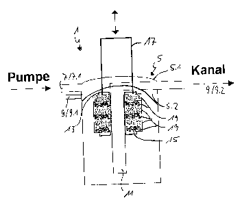
L'invention concerne un dispositif de filtrage pour filtrer l'écoulement de liquides. Ce dispositif comporte un milieu filtrant, pouvant être comprimé et disposé dans un contenant, ainsi qu'un dispositif servant à comprimer le milieu filtrant au moyen d'une poignée d'actionnement, de manière à faire sortir les impuretés dudit milieu filtrant. Ledit dispositif de filtrage comprend en outre un régulateur multivoie dont trois voies d'écoulement pour le filtrage, le rétrolavage et le rinçage peuvent être réglées. Le dispositif de filtrage de la présente invention peut être pourvu seulement d'un régulateur multivoie ou seulement d'un dispositif de compression .


Abrégé anglais


A filter device for filtering flowing liquids comprises a compressible filter
medium in a container and a device with which said medium may be compressed
using an operating handle so that contaminants can be squeezed from the filter
medium. Furthermore a multi-valve is provided in the filter device, which can
be adjusted to perform filtering, back-flushing and flushing by means of three
flow paths. It is also possible to provide the filtration device exclusively
with a multi-valve or a compressing device.

Revendications

Note : Les revendications sont présentées dans la langue officielle dans laquelle elles ont été soumises.


-5-
Claims
1. Filter device for filtering flowing liquids with a vessel and a
compressible filter
medium which is arranged in the vessel along a central flow conduit and which
is arranged
between an inlet area and an outlet area in the main flow direction, and with
a vessel cover in
which the inlet area and the outlet area are integrated, characterized in that
the central flow
conduit (11) is constructed upstream with a first holding surface (13) for the
filter medium (19)
and downstream with a second holding surface (15) for the filter medium (19),
wherein the first
holding surface (13) and the second holding surface (15) are in operative
connection with one
another by means of an actuating element in such a way that the relative
distance between the
two holding surfaces (13, 15) can be varied.
2. Filter device according to claim 1 characterized in that a flow conduit ()
which
completely encloses the filter medium (19) is formed between an inner wall of
the vessel (3) and
the filter medium (19) concentric to the flow conduit (11).
3. Filter device according to claim 1 or 2, characterized in that the
actuating element
(17) is a pull element which is fixed to the second holding surface (15) and
guided at the first
holding surface (13).
4. Filter device according to claim 3, characterized in that the second
holding surface
(15) is arranged in such a way that it can slide at the central flow conduit
(11).
5. Filter device according to one of claims 1 to 4, characterized in that the
central flow
conduit (11) is a filter connection piece.
6. Filter device according to one of the preceding claims, characterized in
that the
outlet area has a first runoff opening (9.1) to a pond and a second runoff
opening (9.2) to a
conduit.

-6-
7. Filter device according to claim 6, characterized in that a multipath
regulator (21) is
arranged in the vessel cover (5) and is selectively displaceable in such a way
that three flow
paths can be adjusted:
main filtering flow path: inlet area (7), filter medium (19), first runoff
opening
(9.1) to the pond;
2. back-rinsing flow path: inlet area (7), second runoff opening (9.1) to the
conduit;
3. back-rinsing flow path: inlet area (7), filter medium (19), second runoff
opening
(9.2) to the conduit.
8. Filter device according to claim 6 or 7, characterized in that the
multipath regulator
(21) comprises a cock tap.
9. Filter device according to one of the preceding claims, characterized in
that the
vessel cover (5) has an upper cover (5.1) and a lower cover (5.2) and is
constructed with flow
conduits to the first and second runoff opening (9.1, 9.2).
10. Filter device according to claim 9, characterized in that the multipath
regulator (21)
is arranged in the lower cover (5.2) or upper cover (5.1).
11. Filter device according to one of the preceding claims, characterized in
that the first
holding surface (13) is the vessel cover (5).
12. Filter device according to one of the preceding claims, characterized in
that the
second holding surface (15) is a vessel bottom.
13. Filter device for filtering flowing liquids with a vessel and a
compressible filter
medium which is arranged in the vessel along a central flow conduit and which
is arranged
between an inlet area and an outlet area in the main flow direction, and with
a vessel cover in
which the inlet area and the outlet area are integrated, characterized in that
the outlet area has a
first runoff opening (9.1) to a pond and a second runoff opening (9.2) to a
conduit, and in that a

-7-
multipath regulator (19) is arranged in the vessel cover (5) and is
selectively displaceable in such
a way that three flow paths can be adjusted:
1. main filtering flow path: inlet area (7), filter medium (19), first runoff
opening
(9.1) to the pond;
2. back-rinsing flow path: inlet area (7), second runoff opening (9.1) to the
conduit;
3. clear-rinsing flow path: inlet area (7), filter medium (19), second runoff
opening
(9.2) to the conduit.
14. Filter device according to claim 13, characterized in that the multipath
regulator
(21) comprises a cock tap.
15. Filter device according to claim 13 or 14, characterized in that the
vessel cover (5)
has an upper cover (5.1) and a lower cover (5.2).
16. Filter device according to claim 15, characterized in that the multipath
regulator
(21) is arranged in the lower cover (5.2).
17. Filter device according to one of claims 13 to 16, characterized in that
the central
flow conduit (11) is constructed upstream with a first holding surface (13)
for the filter medium
(19) and downstream with a second holding surface (15) for the filter medium
(19), wherein the
first holding surface (13) and the second holding surface (15) are in
operative connection with
one another by means of an actuating element in such a way that the relative
distance between
the two holding surfaces (13, 15) can be varied.
18. Filter device according to one of claims 13 to 17, characterized in that a
flow
conduit () which completely encloses the filter medium (19) is formed between
an inner wall of
the vessel (3) and the filter medium (19) concentric to the flow conduit (11).
19. Filter device according to one of claims 13 to 18, characterized in that
the actuating
element (17) is a pull element which is fixed to the second holding surface
(15) and guided at the
first holding surface (13).

-8-
20. Filter device according to one of claims 13 to 19, characterized in that
the second
holding surface (15) is arranged in such a way that it can slide at the
central flow conduit (11).
21. Filter device according to one of claims 13 to 20, characterized in that
the central
flow conduit (11) is a filter connection piece.
22. Filter device according to one of claims 17 to 21, characterized in that
the first
holding surface (13) is the vessel cover (5).
23. Filter device according to one of claims 17 to 22, characterized in that
the second
holding surface (15) is a vessel bottom.

Description

Note : Les descriptions sont présentées dans la langue officielle dans laquelle elles ont été soumises.


CA 02459062 2004-02-27
-1-
5067A-SSPUS
FILTER DEVICE FOR GARDEN PONDS OR SIMILAR
The present invention is directed to a filter device for filtering flowing
liquids with a
vessel and a compressible filter medium which is arranged in the vessel along
a central flow
channel or conduit and which is arranged between an inlet area and an outlet
area in the main
flow direction, and with a vessel cover in which the inlet area and the outlet
area are integrated.
A filter device of the type mentioned above is known in general from the prior
art. Filter
devices of this type have the disadvantage that they are difficult to clean.
The filter devices are
used in ponds to filter suspended matter out of the pond water. Therefore, the
filter medium
becomes stopped up with impurities over time, so that it is necessary to clean
the filter medium.
In order to clean the filter medium in prior art filter devices, it is
necessary to disassemble the
filter device and to clean the filter medium while it is removed from the
filter device.
This process is time-consuming, complicated and can also result in damage to
the filter
device and filter medium.
Therefore, it is the object of the present invention to provide a filter
device of the type
mentioned above which is simple to clean and does not need to be disassembled
for the purpose
of cleaning.
This object is met according to claim 1 in that the central flow conduit is
constructed with
a first holding surface for the filter medium upstream and with a second
holding surface for the
filter medium downstream, wherein the first holding surface and the second
holding surface are
in operative connection with one another by means of an actuating element in
such a way that the
relative distance between the two holding surfaces can be varied.
With the present invention, it is now possible to compress and decompress the
filter
medium in its working position when needed by changing the distance between
the holding
surfaces. By compressing, impurities in the filter medium are pressed out
along with the liquid
present in the filter medium and enter the central flow conduit.
The distance between the two holding surfaces can be reduced selectively by
pressing the
upper holding surface in the direction of the lower holding surface or by
pulling the lower
holding surface in the direction of the upper holding surface.

CA 02459062 2004-02-27
-2-
Further advantageous features of the present invention are indicated in
subclaims 2 to 6.
The cleaning of the filter device according to the invention by compressing
the filter
medium is advantageously supported by a multifunction regulator according to
one of claims 7 to
12. In the positions according to claim 8, the multifunction regulator makes
it possible for the
flowing medium to flow on three flow paths through the filter device. The
normal main flow
path allows filtering of the flowing medium, a second flow path allows back-
rinsing of the filter
device and a third flow path allows clear-rinsing of the filter device. In
addition, the
arrangement of the multifunction regulator in the vessel cover of the filter
device allows the
multifunction regulator to be manufactured with tolerances because possible
small leaks occur in
the interior of the vessel due to dimensional tolerances and do not present
any disadvantages to
be prevented. In addition, costly pipe laying can be dispensed with due to the
flow paths in the
vessel cover.
The above-stated object is further met according to claim 13 in that the
outlet area has a
first runoff opening to a pond and a second runoff opening to a conduit and in
that a
multidirectional or multipath regulator is arranged in the vessel cover and is
selectively
displaceable in such a way that three flow paths can be adjusted:
1. Main filtering flaw path: inlet area, filter medium, first runoff opening
to the pond;
2. Back-rinsing flow path: inlet area, second runoff opening to the conduit;
3. Clear-rinsing flow path: inlet area, filter medium, second runoff opening
to the
conduit.
An embodiment form of the present invention will be described more fully in
the
following with reference to the drawings.
Fig. 1 is a schematic side view in partial section showing a filter device
according to the
invention in which the flow paths are shown;
Fig. 2 is a schematic view of the filter device in Fig. l, wherein an
actuating element is
actuated for decreasing the distance between two holding surfaces;
Figs. 3a, 3b and 3c show schematic top views of a multifunction regulator
according to
the present invention in three different positions.
A filter device 1 comprises a vessel 3 and a vessel cover 5. An inlet area 7
and an outlet
area 9 are formed in the vessel cover 5. The outlet area 9 comprises a first
runoff opening 9.1 to
a pond and a second runoff opening 9.2 to a conduit. The inlet area 7
comprises an inlet opening

CA 02459062 2004-02-27
-3-
7.1 which is connected to a pump by a hose, a line or the like and by which,
e.g., the pond water
to be filtered can be pumped into the filter device 1. A central flow conduit
11 is formed as a
filter connection piece in the vessel 3, i.e., the circumference of the filter
connection piece is
slotted, perforated or the like.
In the vicinity of the vessel cover 5, that is, at the top in Fig. 1, an
upper, first holding
surface 13 is arranged in a stationary manner at the central flow conduit 11
upstream. At the
bottom, that is, at a downstream end of the central flow conduit 11, a lower,
second holding
surface 15 is arranged in such a way that it can slide along the circumference
of the central flow
conduit 11. An actuating element 17 is fixedly connected to the lower holding
surface 15 and is
guided at the upper holding surface 13 and guided outward through the vessel
cover 5. By
actuating the actuating element 17 (see Fig. 2), the lower, second holding
surface 15 can be
pulled along the central flow conduit 11 in the direction of the first holding
surface 13, so that
the distance between the two holding surfaces 13, 1 S is reduced. In this way,
a filter medium 19
which is arranged concentric to the central flow conduit I 1 and between the
holding surfaces 13
and 15 is compressed. The filter medium 19 is, e.g., an open-cell material
which is suitable for
filter functions and is compressible, e.g., a natural or synthetic cellular
material.
In another embodiment form, the upper, first holding surface 13 can also be
arranged so
as to be longitudinally displaceable at the circumference of the central flow
conduit 11 and the
lower, second holding surface 15 is fixedly arranged at the circumference of
the central flow
conduit 11. In this case, the actuating element 17 is then also fixedly
connected to the upper,
first holding surface 13, so that the first, upper holding surface 13 can be
pushed in the direction
of the lower, second holding surface 15 by actuating the actuating element 17.
In other embodiment forms, it is conceivable that the first holding surface 13
is formed
by the vessel cover 5 in case of actuation by pulling and that the second
holding surface 15 is
formed by the vessel bottom in case of actuation by pushing.
The vessel cover 5 has an upper cover 5.1 and a lower cover 5.2. A multipath
regulator
21 (Fig. 3) is arranged in the lower cover 5.2. The multipath regulator 21
serves for selective
adjustment of three flow paths. For this purpose, flow conduits (not shown)
are also formed in
the lower cover 5.2. In other embodiment forms, the multipath regulator 21 and
the flow
conduits can also be constructed in the upper cover 5.1.

CA 02459062 2004-02-27
-4-
In a first position of the multipath regulator 21 (Fig. 3a), a main flow path
is adjusted by
which a liquid to be filtered is guided back to its starting point, e.g., pond
water is guided back
into a pond, through the first runoff opening 9.1 after filtering. In Fig. 3b,
a second flow path is
adjusted in which a flowing medium is directed via the second runoff opening
9.2 into a conduit.
This position is used for back-rinsing the filter device 1. In Fig. 3c a third
flow path is adjusted
in which a flowing medium is likewise directed through the second runoff
opening 9.2 into a
conduit. This flow path is used for clear-rinsing the filter device 1.
The installation of the multipath regulator 21 in the vessel cover 5 allows a
certain
leakage to occur in the multipath regulator 21 which comprises cock taps. This
leakage remains
in the vessel 3 and reaches the first or second runoff opening 9.1, 9.2 by one
of the plurality of
paths.
The vessel 3 has an inner wall 3.1, the filter medium 17 is disposed at a
distance
therefrom. Therefore, a flow conduit 23 is formed between the filter medium 17
and the inner
wall 3.1. This flow conduit 23 extends along the entire height of the filter
medium 17 and runs
concentric to the central flow conduit 11.
In an alternative embodiment form, the cleaning can be carried out chiefly
through
actuation of the multipath regulator 21 and can be supported through the
holding surfaces 13, 15
and the actuating element 17. This is expressed in claims 11 to 19.
. . . ... . r ...

Dessin représentatif
Une figure unique qui représente un dessin illustrant l'invention.
États administratifs

2024-08-01 : Dans le cadre de la transition vers les Brevets de nouvelle génération (BNG), la base de données sur les brevets canadiens (BDBC) contient désormais un Historique d'événement plus détaillé, qui reproduit le Journal des événements de notre nouvelle solution interne.

Veuillez noter que les événements débutant par « Inactive : » se réfèrent à des événements qui ne sont plus utilisés dans notre nouvelle solution interne.

Pour une meilleure compréhension de l'état de la demande ou brevet qui figure sur cette page, la rubrique Mise en garde , et les descriptions de Brevet , Historique d'événement , Taxes périodiques et Historique des paiements devraient être consultées.

Historique d'événement

Description Date
Demande non rétablie avant l'échéance 2008-08-28
Le délai pour l'annulation est expiré 2008-08-28
Demande visant la nomination d'un agent 2008-08-13
Demande visant la révocation de la nomination d'un agent 2008-08-13
Réputée abandonnée - omission de répondre à un avis sur les taxes pour le maintien en état 2007-08-28
Lettre envoyée 2007-03-27
Exigences pour une requête d'examen - jugée conforme 2007-02-23
Toutes les exigences pour l'examen - jugée conforme 2007-02-23
Requête d'examen reçue 2007-02-23
Lettre envoyée 2006-09-11
Exigences de rétablissement - réputé conforme pour tous les motifs d'abandon 2006-08-24
Inactive : CIB de MCD 2006-03-12
Réputée abandonnée - omission de répondre à un avis sur les taxes pour le maintien en état 2005-08-29
Demande visant la révocation de la nomination d'un agent 2004-11-25
Demande visant la nomination d'un agent 2004-11-25
Lettre envoyée 2004-05-06
Inactive : Page couverture publiée 2004-04-28
Exigences relatives à une correction du demandeur - jugée conforme 2004-04-22
Inactive : Notice - Entrée phase nat. - Pas de RE 2004-04-22
Demande reçue - PCT 2004-03-31
Inactive : Transfert individuel 2004-03-25
Exigences pour l'entrée dans la phase nationale - jugée conforme 2004-02-27
Demande publiée (accessible au public) 2003-03-27

Historique d'abandonnement

Date d'abandonnement Raison Date de rétablissement
2007-08-28
2005-08-29

Taxes périodiques

Le dernier paiement a été reçu le 2006-08-24

Avis : Si le paiement en totalité n'a pas été reçu au plus tard à la date indiquée, une taxe supplémentaire peut être imposée, soit une des taxes suivantes :

  • taxe de rétablissement ;
  • taxe pour paiement en souffrance ; ou
  • taxe additionnelle pour le renversement d'une péremption réputée.

Les taxes sur les brevets sont ajustées au 1er janvier de chaque année. Les montants ci-dessus sont les montants actuels s'ils sont reçus au plus tard le 31 décembre de l'année en cours.
Veuillez vous référer à la page web des taxes sur les brevets de l'OPIC pour voir tous les montants actuels des taxes.

Historique des taxes

Type de taxes Anniversaire Échéance Date payée
Taxe nationale de base - générale 2004-02-27
Enregistrement d'un document 2004-03-25
TM (demande, 2e anniv.) - générale 02 2004-08-30 2004-08-23
TM (demande, 4e anniv.) - générale 04 2006-08-28 2006-08-24
Rétablissement 2006-08-24
TM (demande, 3e anniv.) - générale 03 2005-08-29 2006-08-24
Requête d'examen - générale 2007-02-23
Titulaires au dossier

Les titulaires actuels et antérieures au dossier sont affichés en ordre alphabétique.

Titulaires actuels au dossier
OASE WUEBKER GMBH & CO. KG.
Titulaires antérieures au dossier
DIETER HOFFMEIER
Les propriétaires antérieurs qui ne figurent pas dans la liste des « Propriétaires au dossier » apparaîtront dans d'autres documents au dossier.
Documents

Pour visionner les fichiers sélectionnés, entrer le code reCAPTCHA :


Pour visualiser une image, cliquer sur un lien dans la colonne description du document. Pour télécharger l'image (les images), cliquer l'une ou plusieurs cases à cocher dans la première colonne et ensuite cliquer sur le bouton "Télécharger sélection en format PDF (archive Zip)" ou le bouton "Télécharger sélection (en un fichier PDF fusionné)".

Liste des documents de brevet publiés et non publiés sur la BDBC .

Si vous avez des difficultés à accéder au contenu, veuillez communiquer avec le Centre de services à la clientèle au 1-866-997-1936, ou envoyer un courriel au Centre de service à la clientèle de l'OPIC.


Description du
Document 
Date
(aaaa-mm-jj) 
Nombre de pages   Taille de l'image (Ko) 
Abrégé 2004-02-26 1 14
Description 2004-02-26 4 212
Dessins 2004-02-26 3 64
Revendications 2004-02-26 4 142
Dessin représentatif 2004-04-26 1 8
Rappel de taxe de maintien due 2004-04-28 1 109
Avis d'entree dans la phase nationale 2004-04-21 1 192
Courtoisie - Certificat d'enregistrement (document(s) connexe(s)) 2004-05-05 1 106
Courtoisie - Lettre d'abandon (taxe de maintien en état) 2005-10-23 1 176
Avis de retablissement 2006-09-10 1 166
Accusé de réception de la requête d'examen 2007-03-26 1 176
Courtoisie - Lettre d'abandon (taxe de maintien en état) 2007-10-22 1 173
PCT 2004-02-26 9 343
Correspondance 2004-11-24 1 21
Taxes 2006-08-23 2 58
Correspondance 2008-08-12 1 31