Note : Les descriptions sont présentées dans la langue officielle dans laquelle elles ont été soumises.
CA 02460688 2009-07-17
-1-
WELLBORE RECOVERY OPERATION
The present invention relates to methods and equipment for recovering use of a
weilbore in circumstances where the wellbore has become blocked by downhole
equipment.
It is not uncommon for a drill bit to become stuck inhole during downhole oil
and
gas drilling operations. In order to allow retrieval of a downhole drill
string when a drill
bit becomes jammed, it is known to provide a drill string with an emergency
release joint
immediately uphole of the drill bit. During normal operation, the release
joint (commonly
referred to as a shear sub) transmits torque from a motor to the drill bit.
However, in the
event that the drill bit becomes jammed to the extent that axial and
rotational movement of
the drill bit is not possible, the drill bit may be separated from the
remainder of the drill
string by virtue of the release joint. The remainder of the drill string may
then be moved
axially uphole so that specialist retrieving equipment may be run to the drill
bit in a fishing
operation. 'The retrieving equipment engages suitable means provided on the
portion of
release joint attached to the drill bit and is then manipulated so that the
drill bit is subjected
to releasing forces. Once the drill bit has been released from the wellbore,
the retrieving
equipment may be moved uphole, together with the drill bit, so as to reopen
the welibore
for subsequent downhole operations.
Although the aforementioned method of reclaiming use of a wellbore is
generally
effective, there remains the possibility that the drill bit cannot be
conveniently released
from the wellbore and that, as a consequence, subsequent use of the wellbore
is
constrained. In these circumstances, the drill bit must be either destroyed or
a
whipstock/deflector and anchor packer must be run inhole and set above the
drill bit so that
a branch borehole may be cut to bypass the blocked portion of primary
borehole. With
reference to the second of these options, it will be understood that there are
adverse cost
implications in requiring the use of additional downhole equipment.
CA 02460688 2009-07-17
-2-
Prior art document US 2,797,894 discloses a method of reclaiming use of a
wellbore
wherein a deflector is screw threadedly engaged with equipment stuck downhole.
However, orientation of the deflector within the wellbore is determined by the
orientation
of the stuck equipment and this can lead to problems when drilling a branch
borehole
bypassing the blocked portion of prunary borehole.
A first aspect of the present invention provides a method of recovering use of
a
downhole wellbore which has become blocked by downhole equipment jammed in the
wellbore; wherein the downhole equipment comprises a release joint for
permitting
separation of a portion of said equipment, which is jammed within the
wellbore, from the
remainder of said equipment; the method comprising the steps of separating, at
the release
joint, the remainder of said equipment from said jammed portion of equipment;
running the
remainder of said equipment uphole out of the wellbore; running a deflector
assembly
downhole into the wellbore; restricting relative movement between the
deflector assembly
and the wellbore by engaging the deflector assembly with said jammed portion
of
equipment so as to substantially prevent relative rotation between said jammed
portion and
a first portion of deflector assembly engaged therewith; and then deflecting a
milling tool
from the wellbore into surrounding formation by means of the deflector
assembly so as to
form a branch borehole; the method comprising the characterising step of
engaging the
deflector assembly with said januned portion by means of co-operating splines
provided on
the deflector assembly and said jammed portion; the deflector assembly being
rotationally
orientated, into an angular position required when deflecting the milling
tool, prior to the
deflector assembly being engaged with said jammed portion.
A second aspect of the present invention provides a method of recovering use
of a
downhole wellbore which has become blocked by downhole equipment jammed in the
wellbore; wherein the downhole equipment comprises a release joint for
permitting
separation of a portion of said equipment, which is jammed within the
wellbore, from the
CA 02460688 2009-07-17
-3-
remainder of said equipment; the method comprising the steps of separating, at
the release
joint, the remainder of said equipment from said jammed portion of equipment;
running the
remainder of said equipment uphole out of the wellbore; running a deflector
assembly
downhole into the wellbore; restricting relative movement between the
deflector assembly
and the wellbore by engaging the deflector assembly with said jammed portion
of
equipment so as to substantially prevent relative rotation between said jammed
portion and
a first portion of deflector assembly engaged therewith; and deflecting a
milling tool from
the wellbore into surrounding formation by means of the deflector assembly so
as to form a
branch borehole; the method comprising the characterising step of rotationally
orientating a
second portion of deflector assembly into an angular position required when
deflecting the
milling tool, wherein said-orientating step is undertaken following the step
of engaging the
deflector assembly with said jammed portion.
Thus, in a method according to the present invention, once downhole equipment
(such as a drill bit) becomes jammed within a wellbore, a release joint may be
employed in
a conventional manner to separate the jammed portion of equipment from the
remainder
portion of equipment so that said remainder portion may be run uphole out of
the wellbore.
However, rather than then running and setting an anchor packer within the
wellbore, the
method of the present invention provides for the running of a
whipstock/deflector assembly
per se and the engagement of this assembly with said jammed portion of
equipment. In
this way, it is possible to locate the deflector assembly at a desired depth
within the
wellbore and at a required angular orientation without the need for an anchor
packer. The
deflector assembly may then be used to deflect a milling tool into surrounding
formation so
that the blocked portion of primary borehole may be bypassed. The branch
borehole may
be milled so as to rejoin the primary borehole downhole of the blocked
portion. During the
milling operation, reaction forces on the deflecting assembly are transmitted
to the
wellbore wall by means of the jammed portion of equipment. In this way, the
position of
the deflector assembly is maintained whilst the branch borehole is milled.
CA 02460688 2009-07-17
-3a-
Through use of the aforementioned method of the present invention, it will be
clear
than use of an anchor packer is advantageously not required.
When, following the step of engaging the deflector assembly with said jammed
portion, a second portion of deflector assembly is rotationally orientated,
said second
portion of deflector assembly may be rotationally orientated relative to said
first portion of
deflector assembly by means of a swivel sub comprised in the deflector
assembly. It is
also preferable for said swivel sub to be hydraulically actuated and the
aforesaid step of
rotationally orientating said first portion of deflector assembly relative to
said second
portion of deflector assembly to comprise the step of varying fluid pressure
within said
swivel sub. Also, the deflector assembly may be engaged with said jammed
portion by
means of co-operating splines provided on the deflector assembly and said
jammed
portion. Alternatively, the deflector assembly may be engaged with said jammed
portion
by means of co-operating screw threads provided on the deflector assembly and
said
jammed portion.
Furthermore, the step of restricting relative movement between the deflector
assembly and the wellbore may comprise the step of engaging the deflector
assembly with
said jammed portion so as to permit transmission of an axial force from the
deflector
assembly to said jammed portion which acts in an uphole direction on said
jammed
portion.
CA 02460688 2004-03-16
WO 03/031767 PCT/GB02/04423
-4-
A further aspect of the present invention provides a method of
recovering use of a downhole wellbore which has become blocked by downhole
equipment j ammed in the wellbore; wherein the downhole equipment coinprises a
release joint for pennitting separation of a portion of said equipment, which
is jammed
within the wellbore, from the remainder of said equipment; the method
coinprising the
step of separating, at the release joint, the remainder of said equipment from
said
j amined portion of equipment; rumling the remainder of said equipment uphole
out of
the wellbore; and running a deflector assembly downhole into the wellbore; the
method comprising the characterising steps of engaging the deflector assembly
with
said j ammed portion of equipment; transmitting a force from the deflector
assembly to
said j ammed portion of equipment so as to release said portion from the
wellbore; and
running said portion and the deflector assembly uphole out of the wellbore.
Thus, in a method according to the further aspect of the present
invention, once the deflector assembly is engaged with said jammed portion of
equipment, the deflector assembly is manipulated so as to transmit forces to
said
jammed portion in an attempt to free said jammed portion from the wellbore. If
said
jammed portion is released from the wellbore, then it may be run uphole so as
to
reopen the borehole. However, if said jammed portion is not released, then the
deflector assembly may be used to mill a branch borehole in accordance with
the first
aspect of the present invention.
A yet further aspect of the present invention provides a drill bit
comprising a first portion provided with cutting elements and a second portion
provided with cutting elements, the first and second portions being releasably
connected to one another. Preferably, said first and second portions are
releasably
comlected to one another by means of one or more shear pins. The first and
second
portions may also be engaged with one another by means of splines.
A still further aspect of the present invention provides downhole apparatus
comprising a first part connected to a second part by connecting means, the
connecting means liiniting axial and rotational movement of the first part
relative to
CA 02460688 2004-03-16
WO 03/031767 PCT/GB02/04423
-5-
the second part and comprising a frangible member for allowing selective
separation
of the first part from the second part, wherein at least one of the first and
second parts
is provided with cutting elements.
Another aspect of the present invention provides a method of using the
aforementioned apparatus wherein a part of said apparatus provided with
cutting
elelnents is connected to a drill bit.
Embodiments of the present invention will now be described with
reference to the accompanying drawings, in which:
Figure 1 is a cross-sectional side view of a shear sub having an internal
latch fishing neck;
Figure la is a cross-sectional view taken along line 1 a- l a shown in
Figure 1;
Figure lb is a cross-sectional view taken along line lb-lb shown in
Figure 1;
Figure 2 is a cross-sectional side view of a shear sub having reaming
elemeiits located on a lower portion thereof;
Figure 2a is a cross-sectional view taken along line 2a - 2a shown in
Figure 2;
Figure 3 is a cross-sectional side view of a shear sub having reaming
elements located on an upper portion thereof;
Figure 3a is a cross-sectional view taken along line 3a - 3a shown in
Figure 3;
Figure 4 is a cross-sectional side view of a shear sub having an internal
screw threaded fishing neck;
Figure 5 is a schematic side view of a jammed portion of downhole
equipment and a deflector assembly for engagement therewith located within a
wellbore;
Figure 6 is a partial cross-sectional side view of a latch engaging
mechanism of the deflector assembly shown in Figure 3; and
CA 02460688 2004-03-16
WO 03/031767 PCT/GB02/04423
-6-
Figure 7 is a schematic side view of a drill bit comprising an integral
shear sub.
A first shear sub 2 is shown in Figures 1, 1 a and lb of the accompanying
drawings. The first shear sub 2 comprises two principle components, namely an
upper
portion 4 and a lower portion 6, which are interconnected with one another by
means
of a plurality of inter-eiigaging splines 8,10 (see Figure 1 a) and a
plurality of shear
pins 12 (see Figure ib). With reference to Figure la, it will be seen that the
upper
portion 4 is provided with a nuinber of splines 10 which inter-engage with a
number
of splines 8 provided on the lower portion 6. This inter-engagement of splines
8,10
allows rotary forces to be transmitted between the upper and lower portions
4,6 of the
shear sub 2. The plurality of shear pins 12 allow a transmission of axial
force between
the upper and lower portions 4,6. Although the first shear sub 2 is provided
with six
shear pins 12, any nuinber of shear pins may be provided. It will be
understood from
Figures 1, 1 a and lb that the upper and lower portions 4,6 have a generally
cyliiidrical
shape and that an upper end of the lower portion 6 is received within a lower
end of
the upper portion 4. Each shear pin 12 extends through an aperture provided in
the
lower end of the upper portion 4 and locates within a recess defined in the
upper end
of the lower portion 6. In this way, the plurality of shear pins 12 restrict
relative axial
movemeiit between the upper and lower portions 4,6.
A sleeve 14 having a generally cylindrical shape is located about the
lower end of the upper portion 4 so as to cover and protect the shear pins 12.
The
sleeve 14 is retained adj acent an upwardly facing extenlal shoulder 16
provided on the
lower portion 6. The sleeve 14 is retained by ineans of a circlip 18 located
in an
external groove provided in the lower end of the upper portion 4. The circlip
18 and
shoulder 16 are located at upper and lower ends respectively of the sleeve 14
and
thereby prevent axial movement of the sleeve 14 relative to the upper and
lower
portions 4,6.
A bore 20 extends through the upper and lower portions 4,6 so as to
allow fluid communication through the shear sub 2. A seal 221ocated between
the
CA 02460688 2004-03-16
WO 03/031767 PCT/GB02/04423
-7-
upper and lower portions 4,6 serves to prevent the ingress of wellbore fluid
into the
bore 20 from a location exterior to the shear sub 2.
The exterior surface of the upper end of the lower portion 6 is provided
with a circulnferential recess 24. This recess 24 provides ineans by which a
fishing
tool (or other downhole equipment) may become latched to the lower portion 6
once
the upper portion 4 has been removed therefrom. The recess 24 defmes a
downwardly
facing external shoulder 26 which (once the upper portion 4 has been reinoved
from
the lower portion 6) can be engaged by a fishing tool (or other downhole
equipment)
so as to allow an upward force (acting in the direction shown by arrow 26) to
be
applied to the lower portion 6.
The shear sub 2 is provided with external screw threads 28 located at the
upper end of the upper portion 4 and 'ulternal screw threads 30 located at the
lower end
of the lower portion 6 for attachinent of the shear sub to downhole equipment.
For
example, the lower portion 6 will be typically connected to a drill bit by
means of the
internal screw threads 30 whilst the upper portion 4 will be connected to a
drill string
by means of external screw threads 28.
The shear sub 2 may be inodified in a iiumber of ways. For example, the
exterior surfaces of the upper and lower portions 4, 6 may be provided with
cutting
elements. These elements may be used to ream a borehole. Two modified shear
subs
37, 39 are shown in Figures 2 and 3 respectively. Each of these modified shear
subs
37, 39 is substantially identical to the shear sub 2 shown in Figure 1 other
than for the
provision of cutting elements. With regard to the first modified shear sub
shown in
Figure 2, a plurality of cutting elements 33 are embedded in that area of
exterior
surface of the lower portion 6 located below the upper portion 4. With regard
to the
second modified shear sub shown in Figure 3, a plurality of cutting elements
35 are
embedded in an area of the exterior surface of the upper portion 4. In each of
the two
modified shear subs 37, 39 the area of lower or upper portion divided with
cutting
elements has an expanded outer diameter relative to that of the shear sub 2
shown in
Figure 1.
CA 02460688 2004-03-16
WO 03/031767 PCT/GB02/04423
-8-
Alternative means for engaging a fishing tool (or other downhole
equipment) may also be provided. For example, the upper end of the lower
portion 6
may be provided with either an internal or external screw thread. In this
regard,
Figure 4 of the accompanying drawings shows a fiu-ther shear sub 40 which
differs
from the first shear sub 2 only in that the fishing tool engagement means
24,26 of the
first shear sub 2 is replaced by alternative engagement means in the fonn of
internal
screw threads 42 defmed in the upper part of bore provided in the lower
portion 6.
During use of the shear sub in a drilling operation, torque is transmitted
from the drill string to the drill bit by means of the plurality of splines
8,10. If the drill
bit becomes j amined within the wellbore, then an attempt at releasing the
drill bit may
be made by applying axial force. Axial force in a downhole direction (i.e.
opposite to
that indicated by arrow 27) is transmitted through the shear sub by the
abutment of the
upper portion 4 with the shoulder 16 of the lower portion 6. Axial force
acting in an
uphole direction (as indicated by arrow 27) is transmitted through the shear
sub by the
plurality of shear pins 12. However, in the event that the drill bit cannot be
released
from the wellbore, uphole axial force may be increased to such an extent that
the
plurality of shear pins 12 shear allowing the upper portion 4 to move axially
uphole
relative to the lower portion 6. The upper portion 4 of the shear sub 2, 40
may then be
run uphole out of the wellbore together with the drill string attached
thereto. In
removing the upper portion 4, the engaging means 24,26,42 of the lower portion
6 is
exposed.
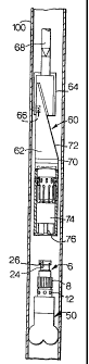
A schematic side view of a drill bit 50 jammed within a wellbore 100 is
shown in Figure 5 of the accompanying drawings. In an attempt to recover use
of the
wellbore 100, Figure 5 illustrates the running downhole of a single trip
whipstock
assembly subsequent to the aforementioned removal of the upper portion 4 of a
shear
sub and associated drill string. The whipstock/deflector assembly 60 is made
up of a
deflector 62 and a milling tool 64 secured to an uphole end of the deflector
62 by
means of release means 66 (such as a shear pin). The deflector 62 has a
surface 72 for
deflecting the milling tool 64 into surrounding formation. The deflector
assembly 60
CA 02460688 2004-03-16
WO 03/031767 PCT/GB02/04423
-9-
is run downhole by means of a conveying string 68 which may be coil tubing or
a
wireline. The deflector asselnbly 60 also coinprises a swivel sub 70 located
between
the deflecting surface 72 and means for engaging the lower portion 6 (see
below).
The swivel sub may be actuated either mechanically or hydraulically so as to
allow
rotation of the deflecting surface 72 relative to said engaging lneans of the
assembly
60. In this way, the deflecting surface 72 may be rotated to a required
angular
orientation once the assembly 60 is engaged with the lower portion 6. Both
hydraulically actuated swivel subs and mechaiiically actuated swivel subs are
well
known in the art and involve the disengagement of internal splines so as to
allow
relative rotation of component parts before a subsequent re-engagement of said
splines
to lock said parts in a required angular orientation. The position of the
deflecting
surface 72 may be monitored through use of Measure-While-Drilling (MWD)
equipment.
As can be seen from Figure 5, the downhole end of the deflector 62 is
provided with engaging means for limiting axial and rotational movement
between the
lower portion 6 and the deflector assembly 60. The form of said means depends
upon
the type of fishing tool engaging means 24,26,42 provided on the lower portion
6. In
circumstances where the lower portion 6 is provided with a screw thread
(whether
internal or external), the lower end of the deflector assembly 60 is provided
with a co-
operating screw thread with such fishing tool engaging means, it is highly
desirable
for a swivel sub to be located between the co-operating screw thread and the
remainder of the deflector assembly 60 (a previously mentioned) so as to allow
rotation of the mill deflecting surface 72 to a required angular orientation
once the
deflector assembly 60 and lower portion 6 have been screw-threadedly engaged
with
one another. It will be understood that the co-operating screw threads of the
lower
portion 6 and deflector assembly 60 limit both relative axial and rotational
movement
thereof.
The provision of a swivel sub is generally not necessary when the
deflector assembly is engaged with the lower portion 6 by means of splines.
This is
CA 02460688 2004-03-16
WO 03/031767 PCT/GB02/04423
-10-
because the splines allow a predetermined orientation of deflector assembly
relative to
lower portion 6 to be fixed when the deflector assembly and lower portion are
pressed
axially together (provided the splines have a fme arrangement allowing a large
number of small variations in relative angular position).
In the arrangement of Figure 5, the lower portion 6 is shown as
described in relation to the first shear sub 2. Accordingly, the engaging
means of the
deflector assembly 60 comprises a bore 74 in which the lower portion 6 is
received.
The lower end of the bore 74 is provided with a plurality of splines 76 which
co-
operate with the plurality of splines 8 provided on the lower portion 6. This
co-
operation of splines allows relative axial moveinent of the lower portion 6
and
deflector assembly 60 whilst limiting relative rotational movement thereof.
Relative
axial movement between the lower portion 6 and the deflector assembly 60 is
limited
by means of engagement of the shoulder 26 of the lower portion 6 with a
plurality of
collet tabs 80 located within the deflector bore 74 (see Figure 6).
With reference to Figure 4, it will be seen that the bore 74 of the
deflector assembly 60 houses a cylindrical member 82. The lower end of the
cylindrical meinber 82 defines the aforementioned plurality of collet tabs 80.
The
lower end of each collet tab 80 is provided with an inwardly radially
extending portion
84 defming an upwardly facing shoulder for engagement with the downwardly
facing
shoulder 26 of the lower portion 6. The upper part of the cylindrical member
82 is
provided with a plurality of axially extending slots 86 for receiving shear
pins 88
fixedly secured to the bore 74. The location of a shear pin 88 in each of the
slots 86
allows limited axial movement of the cylindrical member 82 within the bore 74
but
substantially prevents relative rotational movelnent. As can be most clearly
seen from
Figure 6, the bore 74 is provided with a portion 90 of increased diameter.
With the
cylindrical meinber 82 in its lowermost position within the bore 74 (as shown
in
Figure 6), the free ends of the plurality of collet tabs 80 locate downhole of
said
portion 90 of increased bore diameter. As a result, outward radial movement of
the
free ends of the collet tabs 80 is substantially prevented. However, as the
deflector
CA 02460688 2004-03-16
WO 03/031767 PCT/GB02/04423
-11-
assembly 60 is run downhole and the lower portion 6 is received within the
bore 74,
said lower portion 6 abuts an angled camming surface 92 provided on the end of
each
collet fmger 80. As the deflector assembly 60 is pushed down over the lower
portion
6, the cylindrical portion 80 is pressed upwardly relative to the bore 74. An
outward
radial component of force is also generated on the free ends of the collet
tabs 80 by
virtue of the lower portion 6 acting on the cainlning surfaces 92. Thus, once
the free
ends of the collet tabs 80 are pushed into the portion 90 of expanded bore
diameter,
said collet free ends move radially outwardly. The diameter of the expanded
portion
90 of bore is sufficient to allow the radial deflection of the collet free
ends required
for the shoulder 26 of the lower portion 6 to be received within the
cylindrical member
82. Once said shoulder 26 is received within the cylindrical member 82, the
free ends
of the collet tabs 80 return to their undeformed radial positions as shown in
Figure 4.
As a result, subsequent uphole movement of the deflector asseinbly 60 engages
said
shoulder 26 with the collet shoulders 84. This engagement allows the
cylindrical
member 2 to be moved downwardly relative to the bore 74 back into the position
shown in Figure 4. The lower portion 6 thereby becomes latched to the
deflector
asseinbly 60.
With the deflector assembly 601atched to the lower portion 6, an uphole
axial force may be applied to the lower portion 6 in an attempt to release
said lower
portion 6 from the wellbore. If this attempt fails, then the milling tool 64
may be
deflected from the deflecting surface 72 into the surrounding formation so as
to cut a
branch borehole bypassing the lower portion 6. The deflector assembly 60 may
be
removed from the wellbore by applying an uphole force thereto sufficient to
shear the
shear pins 88.
In an alternative system, the shear sub and a drill bit may be made
integral. Such an assembly, as shown in Figure 7, may be formed by modifying
either
of the shear subs 2, 40 of Figures 1 and 4 by providing the part of the lower
portion 6
located below the upwardly facing shoulder 16 thereof with milling blades 110.
Clearly, the internal screw threads 30 of the lower portion 6 are not required
and the
CA 02460688 2004-03-16
WO 03/031767 PCT/GB02/04423
-12-
bore 20 is therefore preferably sealed so as not to open onto the surface
provided with
the milling blades 110. The external cylindrical surface of the upper portion
4 may be
provided with cutting elements 112 (such as diamond or carbide inserts) for
performing a reaming function. The internal structure of the element shown in
Figure
7 is as illustrated in Figures 1 or 4. The remaining elements 112 may be
provided as
shown in Figure 3.
The present invention is not limited to the specific embodiments
described above. Alternative arrangements will be apparent to a reader skilled
in the
art.