Note : Les descriptions sont présentées dans la langue officielle dans laquelle elles ont été soumises.
CA 02465926 2004-04-30
3105 0069
A TRACTION APPARATUS
BACKGROUND OF THE INVENTION
Field of the Invention
Embodiments of the present invention generally relate to completion
operation. More particularly, the present invention relates to a method and an
apparatus for transporting a tool into a tubular and performing an operation.
Description of the Related Art
The safe and continuous operation of hydrocarbon wellbores and pipeline
networks is essential to the operators and users of such networks.
Accordingly,
such pipeline and welibores are cleaned and inspected at regular intervals to
ensure
their operational integrity.
The conventional approach to inspection of operating pipelines is for the
tubular string to be precleaned several times using a "dumb" pig. The dumb
pig,
without any on-board intelligence, typically operates to scrape and remove
debris
such as wax, scale, sand, and other foreign matter from the tubular. In a
newly
formed pipeline with a new tubular stririg, the step of precleaning may not be
required. In either case, a detailed inspection is subsequently performed by a
"smart" pig, which makes detailed measurements of the tubular string to
determine
the internal condition of the tubular. Ttie smart pig may also be employed to
transport a tool to a predetermined location in the tubular string to perform
various
operations therein. The smart pig is typically equipped with technologies of
varying
sophistication. For example, the smart pig may include a mechanism for
measuring
an interior surface of the tubular string. In another example, the smart pig
may
include techniques such as magnetic flux leakage (MFL) or ultrasonic scanning
(at
various positions along the tubular string) to detect flaws or defects, which
might
prejudice the tubular's integrity. In other examples, the smart pig may
include
complex tools generally comprising arrays of probes and sensors for placement
of
on-line monitoring equipment for later collection or for precise placement of
isolation
components and radioactive devices.
One shortcoming of conventional pigging inspection operations is that a
complicated technique is typically required to position the smart pig at a
1
CA 02465926 2004-04-30
3105 0069
predetermined location in the tubular string prior to the inspection of the
tubular
string. For example, one technique requires reversing the flow of fluid in the
tubular
string to direct the smart pig in the desired direction. This manipulation of
the fluid
flow may cause numerous problems such as storage problems and production
problems. Another technique requires additional components to be constructed
adjacent to the tubular string such as a sub-sea pig facility or a second
line. These
components are used to introduce the smart pig to the predetermined location
in the
tubular string so that the smart pig can conduct an inspection of the tubular
string as
it returns to the platform with the flow of fluid in the tubular string. For
instance, the
second line is constructed adjacent to the tubular string to provide a fluid
pathway to
pump the smart pig from the platform to the predetermined point in the tubular
string.
However, these additional components increase the cost of the conventional
pigging
inspection operation and add undesirable complexity the completion operation.
In a similar manner, a cleaning apparatus or an inspection apparatus may be
employed in a wellbore by urging the cleaning apparatus or the inspection
apparatus
through the wellbore on a string member. However, this technique increases the
cost of the wellbore operation.
More recently, an apparatus commonly known as a tractor has been
developed that is capable of entering a tubular string at a predetermined
point of the
tubular string and traveling through the tubular string. The tractor
subsequently
returns through the same tubular string back to the predetermined point.
However,
the tractor has not been effectively utilized in conjunction with a pig or
other
inspection or cleaning tools requiring transportation through a tubular
string.
A need therefore exists for a method and apparatus of using a tractor in
conjunction with other tools to transport andJor place tools in a pipeline or
a wellbore.
SUMMARY OF THE INVENTION
The present invention generally relates to a method and apparatus for
performing an operation in a tubular string. In one aspect, a method comprises
positioning an apparatus in the tubular, the apparatus having a tractor
portion and an
auxiliary module. The method further includes operating the tractor portion to
move
2
CA 02465926 2004-04-30
3105 0069
the apparatus through the tubular and operating the auxiliary module to
perform the
operation in the tubular.
In another aspect, an apparatus for use in a tubular is provided. The
apparatus comprises a tractor having a drive member for moving the apparatus
in a
desired direction, a turbine member adapted to be driven by moving fluid and a
conversion member for converting movement of the turbine member to power the
drive member. The apparatus further includes an auxiliary module for use in
performing an operation in the tubular.
BRIEF DESCRIPTION OF THE DRAWINGS
So that the manner in which the above recited features of the present
invention can be understood in detail, a more particular description of the
invention,
briefly summarized above, may be had by reference to embodiments, some of
which
are illustrated in the appended drawings. It is to be noted, however, that the
appended drawings illustrate only typical embodiments of this invention and
are
therefore not to be considered limiting of its scope, for the invention may
admit to
other equally effective embodiments.
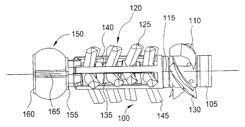
Figure 1 is a sectional view illustrating a traction apparatus with a wax
cutting
module in accordance with the present invention.
Figure 2 is a sectional view illustrating the traction apparatus with a
tubular
wall thickness inspection module.
Figure 3 is a sectional view illustrating the traction apparatus with a
tubular
wall surface inspection module.
Figure 4 is a sectional view illustrating the traction apparatus with a
component placement module.
DETAILED DESCRIPTION OF THE PREFERRED EMBODIMENT
In general, the present invention relates to an apparatus for, and method of,
performing an operation by utilizing a tractor to transport an auxiliary
module into a
tubular. The tractor is an apparatus that is arranged to be driven in the
either
3
CA 02465926 2008-06-25
3105 0069
direction as the fluid in the tubular, but is preferably arranged to be driven
in the
opposite direction to the fluid flow, that is upstream or against the flow.
The tractor
is employed for transporting the auxiliary module capable of performing an
operation such as detecting a physical condition in the tubular by obtaining
data
along the entire length of the tubular string, wherein the data is
representative of the
physical condition. As herein defined, the term "tubular" may refer to a
casing for
use in a wellbore, a pipe for use in a pipeline or any other type of tubular
used in
the oil and gas industry. Furthermore, the term "auxiliary module" is defined
as any
component used to perform an operation in a tubular. To better understand the
novelty of the apparatus of the present invention and the methods of use
thereof,
reference is hereafter made to the accompanying drawings.
Figure 1 is a sectional view illustrating a traction apparatus 100 with a wax
cutting module 150 in accordance with the present invention. Herein, the
components of the apparatus 100 will be described generally as it relates to
the
present invention. The components are described in greater detail in U.S.
Patent
Number 6,722,442, issued to Simpson on April 20, 2004, entitled SUBSURFACE
APPARATUS and U.S. Patent Application Publication 2004/0045474, published on
March 11, 2004, entitled BI-DIRECTIONAL TRACTION APPARATUS.
The apparatus 100 includes a generally cylindrical body 105 upon which is
mounted a rotatable member 110. The rotatable member 110 is typically a
turbine
rotor having a number of generally helical blades 130. The rotatable member
110
is operatively attached to a central drive shaft (not shown) via a conversion
member
115 such as a gear box. The central drive shaft provides power to a drive
member
120. Generally, the drive member 120 comprises a plurality of leg members 125.
The leg members 125 each comprise a cam 135 mounted on the drive shaft
and six elastomer or compression fingers 145 which are oscillated or swashed
backwards and forwards by the rotation of the drive shaft. As described in
U.S. Pat.
No. 6,722,442, the cams 135 are offset to vary the traction provided by each
leg
member 125 such that rotation of the drive shaft will cause the apparatus 100
to
move through a tubular (not shown) contacted by the ends of the fingers 145.
The
fingers 145 are mounted on the respective cams 135 via bearings 140 and by
4
CA 02465926 2004-04-30
3105 0069
moving the fingers 145 from one side of the bearing center line to the other
it is
possible to reverse the direction of traction and to facilitate movement of
the
apparatus 100 in the opposite direction to the original drive direction.
It is within the scope of the present invention to capture and use the excess
power generated by the rotatable member 110 in the apparatus 100 to power the
auxiliary module, such as the wax cutting module 150. This may be accomplished
by capturing the energy either mechanically, hydraulically, or electrically
directly from
the conversion member 115. Additionadly, the rotation of the drive shaft could
be
used to rotate a sensor for inspection purposes.
The wax cutting module 150 is adapted to fit at the front end of the apparatus
100 for use in breaking up wax and other deposits from a wall of the tubular.
The
wax cutting module 150 is operatively attached to the drive shaft through a
gear box
(not shown) to provide an appropriate rotational speed. Typically, the wax
cutting
module 150 includes two cutting blades (not shown) mounted within respective
rings
155, 160. The wax cutting module 150 also includes a set of axially and
radially
extending blades 165 between the two rings 155, 160.
In operation, the wax cutting module 150 is rotated and urged through the
tubular by the apparatus 100 to break up wax and other deposits on the inner
surface of the tubular. Upon dislodging the wax and other deposits such as
scale or
asphaltene, the deposits are washed past the apparatus 100 and subsequently
out
of the tubular by flowing fluid in the opposite direction to the directional
movement of
the apparatus 100. In another embodiment, brush members (not shown) may be
attached to an outer surface of several fingers 145. As the apparatus 100
moves
through the tubular, the brush members are oscillated or swashed backwards and
forwards along with fingers 145 to break up wax and other deposits on the
inner
surface of the tubular. As set forth above, the deposits are then washed past
the
apparatus 100 by flowing fluid in the opposite direction to the directional
movement
of the apparatus 100.
Figure 2 is a sectional view illustrating the traction apparatus 100 with a
tubular wall thickness inspection module 200. In a similar manner as set forth
5
CA 02465926 2008-06-25
3105 0069
above, the tubular wall thickness inspection module 200 is transported through
the
tubular attached to the apparatus 100.
The tubular wall thickness inspection module 200 is adapted to fit at the
front
end of the apparatus 100 for use in measuring the thickness of the tubular
using an
electromagnetic technique. The result is presented as a type of tubular-
inspection
log, giving an estimate of metal loss and detecting corrosion. In operation, a
coil 205
centered inside the tubular generates an alternating magnetic field. Another
coil (not
shown) measures the phase shift introduced by the tubular. This phase shift
depends on the tubular-wall thickness and internal diameter, as well as the
tubular
conductivity and magnetic permeability. The effects change at different
frequencies,
so that by varying the frequency, the thickness and internal diameter can be
uniquely
determined. It should be noted that an array of electromagnetic members may
employed with the apparatus 100 without departing from principles of the
present
invention. An example of a magnet assembly for pipeline inspection equipment
is
described in GB 1510225 and GB 1535252. Electromagnetic thickness can also be
measured using other techniques such as a tubular-potential profile or a flux-
leakage
measurement.
In another embodiment, an ultrasonic caliper (not shown) may be employed in
the tubular wall thickness inspection module 200. The ultrasonic caliper is a
device
for measuring the internal diameter of the tubular using high-frequency
acoustic
signals. In operation, a transducer (not shown) emits a high-frequency pulse
that is
reflected by the tubular wall back to the transducer. The diameter is
determined
from the time of flight of this echo and the fluid acoustic velocity. The
transducer is
rotated to produce a cross section of the tubular size and full-coverage
images of the
tubular wall. The measurement has high resolution and is used to detect
deformations, the buildup of scale, or metal loss due to corrosion. The
amplitude of
the echo from the inner tubular surface provides qualitative information on
the state
of the surface, such as corrosion. Tubular thickness may also be measured
simultaneously, either by analysis of the tubular resonance signal or by
detecting
separately the echoes from the inner and outer tubular surfaces. It should be
noted
that an array of ultrasonic calipers may employed with the apparatus 100
without
departing from principles of the present invention.
6
CA 02465926 2004-04-30
3105 0069
Figure 3 is a sectional view illustrating the traction apparatus 100 with a
tubular wall surface inspection module 250. In a similar manner as set forth
above,
the surface inspection module 250 is transported through the tubular attached
to the
apparatus 100.
As illustrated, the wall surface inspection module 250 is adapted to fit at a
back end of the apparatus 100 for use in measuring the interior surface of the
tubular
string using a multifinger caliper 255 having a plurality of arms 260. By
using a large
number of arms 260 or fingers, the caliper 255 can detect small changes in the
wall
of the tubular. The main purpose of the measurement is to detect deformations,
the
buildup of scale, or metal loss due to corrosion. In operation, the wall
surface
inspection module 250 is urged through the tubular by the apparatus 100 to
measure
the interior surface of the tubular. Upon contact with a deformation in the
tubular, the
arms 260 move radially and subsequently send a signal to a memory storage unit
(not shown) in the surface inspection moduie 250 for later use in profiling
the interior
surface of the tubular.
In another embodiment, an inspection camera (not shown) may be employed
in the tubular wall surface inspection module 250. The camera is appropriately
positioned to take pictures of the interior surface of the tubular as the
apparatus 100
moves therethrough. The camera may also be rotated to capture full coverage
images of the interior surface of the tubular by operatively attaching the
camera to
the drive shaft via a gear box (not shown) to provide an appropriate
rotational speed.
Figure 4 is a sectional view illustrating the traction apparatus 100 with a
component placement module 300. In a similar manner as set forth above, the
component placement module 300 is transported through the tubular attached to
the
apparatus 100.
As illustrated, the component placement module 300 is adapted to fit at a
back end of the apparatus 100 for use in the placement of components 320 in
the
tubular. The components 320 may be used for acquiring data representative of
characteristics of contents of the tubular at predetermined locations in the
tubular.
The components 320 may also be used for acquiring data about the other
characteristics of the tubular, such as temperature and pressure. It should be
7
CA 02465926 2008-06-25
3105 0069
understood, however, that the component placement module 300 may be located at
any position on the apparatus 100, without departing from principles of the
present
invention.
The component placement module 300 typically includes a sensor 305, such
as an odometer, for determining the distance traveled by the apparatus 100 in
the
tubular. The component placement module 300 further includes a chamber 310 for
housing the components 320. The chamber 310 includes an ejection device 315
for
ejecting the components 320 at the predetermined location in the tubular. An
example of a method and an apparatus for monitoring conditions in pipelines is
described in WO 02/16908.
In operation, the component placement module 300 is urged through the
tubular by the apparatus 100 to place the components 320 in the tubular. As
the
apparatus 100 and the component placement module 300 approach a
predetermined location in the tubular, the sensor 305 sends a signal to the
ejection
device 315 to release one of the components 320 from the chamber 310. After
the
component 320 is placed in the tubular, the apparatus 100 and placement module
300 both travel through the tubular to the next predetermined location and the
ejection procedure is repeated until each component 320 is positioned in the
tubular.
Thereafter, the components 320 collect data for a predetermined period of time
and
then may be collected to obtain the data or the data is read by an external
device
(not shown).
In another embodiment, the component placement module 300 and apparatus
100 may be adapted to transport and place an isolation member (not shown) at a
predetermined location in the tubular. The isolation member may be released in
a
similar manner as discussed above by using the sensor 305 to determine the
predetermined location and using the ejection device 315 to release and
activate the
isolation member. Thereafter, a portion of the tubular is isolated from
another
portion of the tubular.
In another embodiment, the component placement module 300 and apparatus
100 may be adapted to transport and place a member (not shown) having a
detectable source of signals, such as a tracker or location tool, at a
predetermined
8
CA 02465926 2004-04-30
3105 0069
location in the tubular. The member typically emits acoustic or radio signals.
The
member may be released in a similar manner as discussed above by using the
sensor 305 to determine the predetermined location and using the ejection
device
315 to release and activate the member,,
In another embodiment, a sampling module (not shown) may be adapted to fit
on the apparatus 100 for sampling product or contaminant, such as water at
tubular
low points. In a similar manner as set forth above, the sampling module is
transported through the tubular attached to the apparatus 100. Preferably, the
sampling moduie includes a timer or a sensor that sends a signal to open the
container at a predetermined location iri the tubular and then close the
container
after it fills with product or contaminant. Thereafter, the apparatus 100
returns the
sampling module back to the surface of the tubular or to another predetermined
location.
While the foregoing is directed to embodiments of the present invention, other
and further embodiments of the invention may be devised without departing from
the
basic scope thereof, and the scope thereof is determined by the claims that
follow.
9