Sélection de la langue

Search

Sommaire du brevet 2468186 

Énoncé de désistement de responsabilité concernant l'information provenant de tiers

Une partie des informations de ce site Web a été fournie par des sources externes. Le gouvernement du Canada n'assume aucune responsabilité concernant la précision, l'actualité ou la fiabilité des informations fournies par les sources externes. Les utilisateurs qui désirent employer cette information devraient consulter directement la source des informations. Le contenu fourni par les sources externes n'est pas assujetti aux exigences sur les langues officielles, la protection des renseignements personnels et l'accessibilité.

Disponibilité de l'Abrégé et des Revendications

L'apparition de différences dans le texte et l'image des Revendications et de l'Abrégé dépend du moment auquel le document est publié. Les textes des Revendications et de l'Abrégé sont affichés :

  • lorsque la demande peut être examinée par le public;
  • lorsque le brevet est émis (délivrance).
(12) Brevet: (11) CA 2468186
(54) Titre français: FICHE TOURNANTE ET PRISE MURALE
(54) Titre anglais: REVOLVABLE PLUG AND SOCKET
Statut: Périmé et au-delà du délai pour l’annulation
Données bibliographiques
Abrégés

Abrégé français

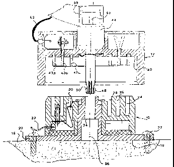
L'invention a trait au support d'appareils électriques légers tels que luminaires et petits ventilateurs. Le dispositif de l'invention combine une fiche tournante (12) et une prise murale (10) permettant d'alimenter et de soutenir un appareil de sorte que l'utilisateur puisse changer l'orientation de celui-ci. Cette combinaison est particulièrement utile lorsque des appareils légers doivent être déplacés fréquemment. Ladite combinaison comprend une prise murale (20) pouvant être fixée et une fiche (12) capable de tourner dans celle-ci pour alimenter en courant électrique et soutenir mécaniquement dans une orientation voulue l'appareil branché.


Abrégé anglais


The invention relates to the support of light electric appliances such as
light fittings and small fans. The device (Fig. 2) accoring to the invention
provides a plug (12) and socket (10) combination powering and supporting an
appliance in a manner allowing the user to change its orientation. The
combination is particularly useful where there is a frequent need to move
light appliances from one location to another. The combination comprises a
fixable socket (20) and a plug (12) revolvable therein for conducting electric
power and for mechanically supporting in a desired orientation an appliance
receiving the power.

Revendications

Note : Les revendications sont présentées dans la langue officielle dans laquelle elles ont été soumises.


CLAIMS
1. A combination of a fixable socket and a plug revolvable therein
for conducting electric power and for mechanically supporting in a desired
orientation an appliance receiving said power, said combination comprising:
a) a socket rigidly attachable to a wall or ceiling, said socket
comprising a non-conductive body including at least two spaced-apart hollow
arcuate conducting receptacles insulated from each other and having a
common center of curvature and being connectable to an electric power
supply, said socket rigidly supporting a first structural element of a
mechanical connection located at said center of curvature;
b) a plug also comprising a non-conductive body, rigidly attachable to,
and configured to mechanically support an appliance from a first face, said
plug supporting from a second face at least two projecting conducting prong
elements insulated from each other and engageable with said at least two
arcuate receptacles respectively and connectable to conductors for feeding
electric power to said appliance, said plug also including a second structural
element engageable to said first structural element of said mechanical
connection and allowing said plug to revolve at least part of a revolution
about
said center of curvature; and
c) releasable latching means attached to said combination, providing
when engaged a retention force between said socket and said plug to prevent
disengagement and to support said appliance.
2. The socket and plug combination as claimed in claim 1, wherein
said first structural element comprises an aperture and said second structural
element comprises a post-like male member engageable with said aperture.
3. The socket and plug combination as claimed in claim 2, wherein
said releasable latching means is a captive ball decent.

4. The socket and plug combination as claimed in claim 2, wherein
both parts of said mechanical connection are conductive and are arranged to
be wired for use as an earth connection.
5. The socket and plug combination as claimed in claim 1, wherein
said latching means engages said first structural element with sufficient
retention force to support a two kg appliance in a ceiling socket during an
earthquake of a severity not causing structural damage to the building in
which said combination is installed.
6. The socket and plug combination as claimed in claim 1, wherein
said appliance is an electric light fitting.
11

Description

Note : Les descriptions sont présentées dans la langue officielle dans laquelle elles ont été soumises.


CA 02468186 2009-01-08
REVOLVABLE PLUG AND SOCKET
FIELD AND BACKGROUND OF THE INVENTION
The present invention relates to the support of light electric appliances
such as light fittings and small fans.
More particularly, the invention provides a plug and socket combination
powering and supporting an appliance in a manner allowing the user to
change its orientation. The combination is particularly useful where there is
a
frequent need to move light appliances from one location to another.
In a previous disclosure, Israel Patent no. 126246, the present
inventors described a socket and plug combination for conducting electric
power and for mechanically supporting a light-weight appliance by means of
said plug. Such appliance can be a light, camera, small TV receiver, TV
camera, a small fan or the like.
In our earlier patent the socket has prong-receiving receptacles similar
to those found on conventional sockets. Consequently, after the appliance
was plugged into the socket, which itself was rigidly attached to a wall or
ceiling, the orientation of the appliance attached to the plug could no longer
be changed. Where the item being installed is substantially symmetrical, for
example a common incandescent filament lamp mounted in a cylindrical lamp
socket, such restriction is meaningless. There are however many lighting
fixtures with reflectors which

CA 02468186 2004-05-25
WO 03/044906 PCT/1L01/01078
need to be oriented in a certain direction, or may be expected to serve a user
in
two proximate but different locations. With regard to a non-oscillating fan,
or a
small television camera or receiver, directional orientation is most important
for
effective use thereof.
In US Patent no. 4,753,600 Williams discloses an electrical connector for
io use with hand tools joined to drop cords. The connector is placed in the
cord and
allows unlimited rotation without twisting the cable. The connector is not
attachable
to a building surface and can not support any load.
The rotatable electric connector proposed by Salzberg in US Patent no.
6,068,490 is arranged to be plugged into a wall socket but not to support any
load
therefrom apart for its own weight. A revolvable portion carries a cable
terminated
by an electric socket.
OBJECTS OF THE INVENTION
It is therefore one of the objects of the present invention to obviate the
limitations of prior art electrical plugs and sockets and to provide an
assembly
which is configured to both support and power a revolvable load, i.e. an
electric
appliance.
It is a further object of the present invention to reduce cost by providing an
embodiment for single phase supply line requiring only two slip rings in place
of the
three slip rings in prior-art revolvable plugs.
2

CA 02468186 2004-05-25
WO 03/044906 PCT/1L01/01078
SUMMARY OF THE INVENTION
The present invention achieves the above objects by providing a
combination of a fixable socket and a plug revolvable therein for conducting
electric power and for mechanically supporting in a desired orientation an
io appliance receiving said power, said combination comprising:
a) a socket rigidly attachable to a wall or ceiling, said socket comprising a
non-conductive body including at least two spaced-apart hollow arcuate
conducting
receptacles insulated from each other and having a common center of curvature
and being connectable to an electric power supply, said socket rigidly
supporting a
first structural element of a mechanical connection located at said radius of
curvature;
b) a plug also comprising a non-conductive body, rigidly attachable to,
and configured to mechanically support an appliance from a first face, said
plug
supporting from a second face at least two projecting conducting prongs
insulated
from each other and engagable with said at least two arcuate receptacles
respectively and connectable to conductors for feeding electric power to said
appliance, said plug also including a second structural element engagable to
said
first structural element of said mechanical connection and allowing said plug
to
revolve at least part of a revolution about said center of curvature; and
3

CA 02468186 2004-05-25
WO 03/044906 PCT/1L01/01078
s c) releasable latching means attached to said combination, providing when
engaged a retention force between said socket and said plug to prevent
disengagement and to support said appliance.
In a preferred embodiment of the present invention there is provided a
socket and plug combination wherein said first structural element comprises an
io aperture and said second structural element comprises a post-like male
member
engagable with said aperture.
In a most preferred embodiment of the present invention there is provided
socket and plug combination wherein both parts of said mechanical connection
are
conductive and are arranged to be wired for use as an earth connection.
15 Yet further embodiments of the invention will be described hereinafter.
It will thus be realized that the novel connector of the present invention
serves to allow fast installation of small electrical appliances. Unlike the
industrial
bus-bar, the present invention maintains a standard of appearance appropriate
to
residential areas. The ability of varying the orientation of the supported
appliance is
20 additional to the facility of fast exchange for another appliance fitted
with a plug
according to the present invention.
The present specification does not describe a locking device for retaining
the plug in a desired orientation, which is a desirable addition. The prior
art
however describes many types of locking, braking, detent or location retention
25 device, and an appropriate locking device can easily be added to the plug-
socket
combination of the present invention to retain the plug in any desired
position.
4

CA 02468186 2004-05-25
WO 03/044906 PCT/1L01/01078
BRIEF DESCRIPTION OF THE DRAWINGS
The invention will now be described further with reference to the
accompanying drawings, which represent by example preferred embodiments of
the invention. Structural details are shown only as far as necessary for a
fundamental understanding thereof. The described examples, together with the
drawings, will make apparent to those skilled in the art how further forms of
the
invention may be realized.
In the drawings:
FIG. 1 is a non-detailed perspective view of a preferred embodiment of the
socket and plug combination attached to a wall, according to the invention;
FIG. 2 is a sectional elevational view of the same embodiment showing the
plug before engagement with socket;
FIG. 3 is a sectional elevational view of an embodiment attached to a
ceiling and supporting a fan;
FIG. 4 is a plan view of the socket seen in FIGS 1 and 2;
FIG. 5 is a detail sectional elevation of a second embodiment of the
release mechanism;
and
FIG. 6 is a perspective view of the plug-socket combination supporting a
lighting fixture.
5

CA 02468186 2004-05-25
WO 03/044906 PCT/1L01/01078
DETAILED DESCRIPTION OF THE PRESENT INVENTION
There is seen in FIGS. 1, 2 and 4 a combination of a fixable socket 10 and
a plug 12. The plug 12 is revolvable in the socket 10, and receives electric
power
therefrom. The combination 10 + 12 serves also for mechanically supporting in
a
io desired orientation a light appliance 14, in the present example a
miniature
television receiver, receiving said power.
The socket 10 is shown in the present figure attached to a wall 16, seen in
FIG. 2. The socket 10 has a flat base 18 and apertures 20 to allow the passage
of
screws 22. The socket 10 has a non-conductive body made of a plastic. Three
spaced-apart hollow arcuate conducting receptacles 24, 26, 28, seen most
clearly
in FIG. 4, are insulated from each other and have a common center of curvature
36. All three receptacles 24, 26, 28 comprise molded recesses containing
conductive inserts 30, one of which is seen in FIG. 2, which can be
permanently
connected by wires 32 to an electric power supply.
The socket 10 rigidly supports a first structural element 34, comprising a
cylindrical aperture, of a mechanical connection located at the center of the
radius
of curvature 36 of the conducting receptacles 24, 26, 28.
A plug 12 also made of a plastic is configured to match the socket 10. The
plug body is made of a plastic, and is somewhat larger than conventional plugs
to
enable the plug to rigidly support an appliance from a first face 38. The plug
10 has
6

CA 02468186 2004-05-25
WO 03/044906 PCT/1L01/01078
a second face 40 for mechanically supporting the conductive prong rings 43
a,b,c.
The appliance 14 weight is about 0.5 to 5 kg, depending on the support
configuration in the case of wall attachment. The shorter the distance between
the
wall 16 and the appliance center of gravity 42, the higher the load which can
be
supported.
Three projecting conducting prong rings insulated from each other are
positioned to be engagable with the three arcuate receptacles 24, 26, 28 of
the
socket 10, respectively. The prong rings are connected to conductors 62 for
feeding electric power to the appliance 14.
The plug 12 also supports a second structural element 44, engagable to
the first structural element 34 of the mechanical connection and allowing the
plug
12 to revolve at least part of a revolution about the center of curvature 36.
Preferably and as seen in the figure, the first structural element 34
comprises an aperture and the second structural element 44 comprises a post-
like
male member engagable with the aperture 34. The reverse order, that is where
the
socket 10 carries the male member, is also feasible.
Releasable latching means 46 retain the plug 12 in the socket 10, by
providing a retention force between the socket and the plug to prevent
disengagement and to support the appliance. In the present embodiment latching
means 46 comprises a split expandable post end 48 with a shoulder 50. An
internal shouldered push rod 52 is axially moved to expand the split end 48,
enabling the shoulder 50 to abut the aperture of the first structural element
44.
7

CA 02468186 2004-05-25
WO 03/044906 PCT/1L01/01078
s Latching means 48 are sized to engage the first structural element 44 with
sufficient retention force to support a two kg appliance 14 in a ceiling
socket during
an earthquake of a severity not causing structural damage to the building in
which
the combination is installed. Users will not expect an appliance to continue
to be
supported following a severe earthquake, which damages the building structure
io itself.
With reference to the rest of the figures, similar reference numerals have
been used to identify similar parts.
FIG. 3 shows an embodiment of an interconnected socket 10 and plug 54.
The socket 10 is seen attached to a ceiling 56. The plug 54 supports a fan 58,
15 which can be directed to face any desired direction by revolving the plug
54 in its
socket 10. The bowl-shaped cover 60 is added to improve appearance and to
prevent users making contact with electric wires 32, 62. The inner assembly is
similar to the plug 12 and socket 10 shown not yet interconnected in FIG. 2.
Referring now to FIG. 5, there is depicted a detail of a socket 64 and plug
20 66 combination wherein both parts 68, 70 of the mechanical connection are
conductive and are arranged to be wired for use as an earth connection. It
will be
appreciated that the earth plug prong ring, 43b in FIG. 2, is eliminated from
the
plug, an arcuate recess 26 in FIG. 2 is eliminated from the socket, and both
plug
and socket can be made smaller.
25 The socket 64 rigidly supports a first structural element 68 of a
mechanical
connection is located at the radius of curvature 36. Element 68 is a female
metal
8

CA 02468186 2004-05-25
WO 03/044906 PCT/1L01/01078
component molded into the plastic body 66. Due to the high stress on element
68,
a metal construction is in any case an advantage, thus opening the option of
utilizing the mechanical connection as an earth connector.
The retention mechanism in the present embodiment comprises a plurality
of hard captive balls 72 which are shown in the figure at their outer
position. The
balls 72 retain the plug 66 in the socket 64, as the post 70 can not be
withdrawn
through the element 68 while the balls 72 project outwards. Pushing the rod 74
inwards, against the compression spring 76 allows the balls 72 to retract into
a
recess 78 to allow withdrawal of the plug 66.
FIG. 6 shows a socket 80 and plug 82 combination similar to that seen in
FIG. 1. The appliance being powered and supported is an electric light fitting
84.
The hollow support arm 86 carrying cables 88 is attached to the side of the
plug
82. The light fitting 84 can be quickly installed, adjusted to radiate in a
desired
direction, and quickly removed when not needed - without the aid of tools.
The scope of the described invention is intended to include all
embodiments coming within the meaning of the following claims. The foregoing
examples illustrate useful forms of the invention, but are not to be
considered as
limiting its scope, as those skilled in the art will readily be aware that
additional
variants and modifications of the invention can be formulated without
departing
from the meaning of the following claims.
9

Dessin représentatif
Une figure unique qui représente un dessin illustrant l'invention.
États administratifs

2024-08-01 : Dans le cadre de la transition vers les Brevets de nouvelle génération (BNG), la base de données sur les brevets canadiens (BDBC) contient désormais un Historique d'événement plus détaillé, qui reproduit le Journal des événements de notre nouvelle solution interne.

Veuillez noter que les événements débutant par « Inactive : » se réfèrent à des événements qui ne sont plus utilisés dans notre nouvelle solution interne.

Pour une meilleure compréhension de l'état de la demande ou brevet qui figure sur cette page, la rubrique Mise en garde , et les descriptions de Brevet , Historique d'événement , Taxes périodiques et Historique des paiements devraient être consultées.

Historique d'événement

Description Date
Inactive : Regroupement d'agents 2018-09-01
Inactive : Regroupement d'agents 2018-08-30
Le délai pour l'annulation est expiré 2013-11-22
Lettre envoyée 2012-11-22
Inactive : TME en retard traitée 2011-11-22
Lettre envoyée 2010-11-22
Accordé par délivrance 2010-09-28
Inactive : Page couverture publiée 2010-09-27
Préoctroi 2010-07-13
Inactive : Taxe finale reçue 2010-07-13
Un avis d'acceptation est envoyé 2010-01-15
Lettre envoyée 2010-01-15
Un avis d'acceptation est envoyé 2010-01-15
Inactive : Approuvée aux fins d'acceptation (AFA) 2010-01-13
Lettre envoyée 2009-11-20
Exigences de rétablissement - réputé conforme pour tous les motifs d'abandon 2009-11-20
Modification reçue - modification volontaire 2009-01-08
Réputée abandonnée - omission de répondre à un avis sur les taxes pour le maintien en état 2008-11-24
Inactive : Dem. de l'examinateur par.30(2) Règles 2008-07-08
Inactive : Dem. de l'examinateur art.29 Règles 2008-07-08
Lettre envoyée 2006-10-18
Requête d'examen reçue 2006-09-28
Exigences pour une requête d'examen - jugée conforme 2006-09-28
Toutes les exigences pour l'examen - jugée conforme 2006-09-28
Inactive : CIB de MCD 2006-03-12
Lettre envoyée 2005-06-17
Inactive : Transfert individuel 2005-05-25
Exigences relatives à la révocation de la nomination d'un agent - jugée conforme 2004-12-09
Inactive : Lettre officielle 2004-12-09
Exigences relatives à la nomination d'un agent - jugée conforme 2004-12-09
Demande visant la révocation de la nomination d'un agent 2004-11-22
Demande visant la nomination d'un agent 2004-11-22
Inactive : Page couverture publiée 2004-07-27
Inactive : Lettre de courtoisie - Preuve 2004-07-27
Inactive : Notice - Entrée phase nat. - Pas de RE 2004-07-23
Demande reçue - PCT 2004-06-25
Exigences pour l'entrée dans la phase nationale - jugée conforme 2004-05-25
Demande publiée (accessible au public) 2003-05-30

Historique d'abandonnement

Date d'abandonnement Raison Date de rétablissement
2008-11-24

Taxes périodiques

Le dernier paiement a été reçu le 2009-11-20

Avis : Si le paiement en totalité n'a pas été reçu au plus tard à la date indiquée, une taxe supplémentaire peut être imposée, soit une des taxes suivantes :

  • taxe de rétablissement ;
  • taxe pour paiement en souffrance ; ou
  • taxe additionnelle pour le renversement d'une péremption réputée.

Les taxes sur les brevets sont ajustées au 1er janvier de chaque année. Les montants ci-dessus sont les montants actuels s'ils sont reçus au plus tard le 31 décembre de l'année en cours.
Veuillez vous référer à la page web des taxes sur les brevets de l'OPIC pour voir tous les montants actuels des taxes.

Historique des taxes

Type de taxes Anniversaire Échéance Date payée
TM (demande, 2e anniv.) - générale 02 2003-11-24 2004-05-25
Taxe nationale de base - générale 2004-05-25
TM (demande, 3e anniv.) - générale 03 2004-11-22 2004-11-22
Enregistrement d'un document 2005-05-25
TM (demande, 4e anniv.) - générale 04 2005-11-22 2005-11-10
TM (demande, 5e anniv.) - générale 05 2006-11-22 2006-09-28
Requête d'examen - générale 2006-09-28
TM (demande, 6e anniv.) - générale 06 2007-11-22 2007-11-16
TM (demande, 8e anniv.) - générale 08 2009-11-23 2009-11-20
Rétablissement 2009-11-20
TM (demande, 7e anniv.) - générale 07 2008-11-24 2009-11-20
Taxe finale - générale 2010-07-13
TM (brevet, 9e anniv.) - générale 2010-11-22 2011-11-22
Annulation de la péremption réputée 2010-11-22 2011-11-22
TM (brevet, 10e anniv.) - générale 2011-11-22 2011-11-22
Titulaires au dossier

Les titulaires actuels et antérieures au dossier sont affichés en ordre alphabétique.

Titulaires actuels au dossier
SAFETY QUICK LIGHT LTD.
Titulaires antérieures au dossier
RAN KOHEN
Les propriétaires antérieurs qui ne figurent pas dans la liste des « Propriétaires au dossier » apparaîtront dans d'autres documents au dossier.
Documents

Pour visionner les fichiers sélectionnés, entrer le code reCAPTCHA :


Pour visualiser une image, cliquer sur un lien dans la colonne description du document. Pour télécharger l'image (les images), cliquer l'une ou plusieurs cases à cocher dans la première colonne et ensuite cliquer sur le bouton "Télécharger sélection en format PDF (archive Zip)" ou le bouton "Télécharger sélection (en un fichier PDF fusionné)".

Liste des documents de brevet publiés et non publiés sur la BDBC .

Si vous avez des difficultés à accéder au contenu, veuillez communiquer avec le Centre de services à la clientèle au 1-866-997-1936, ou envoyer un courriel au Centre de service à la clientèle de l'OPIC.


Description du
Document 
Date
(aaaa-mm-jj) 
Nombre de pages   Taille de l'image (Ko) 
Description 2004-05-24 9 343
Revendications 2004-05-24 2 66
Dessin représentatif 2004-05-24 1 25
Dessins 2004-05-24 4 112
Abrégé 2004-05-24 1 63
Description 2009-01-07 9 344
Revendications 2009-01-07 2 61
Dessin représentatif 2010-08-31 1 20
Avis d'entree dans la phase nationale 2004-07-22 1 193
Demande de preuve ou de transfert manquant 2005-05-25 1 100
Courtoisie - Certificat d'enregistrement (document(s) connexe(s)) 2005-06-16 1 114
Rappel - requête d'examen 2006-07-24 1 116
Accusé de réception de la requête d'examen 2006-10-17 1 176
Courtoisie - Lettre d'abandon (taxe de maintien en état) 2009-01-18 1 173
Avis de retablissement 2009-11-19 1 162
Avis du commissaire - Demande jugée acceptable 2010-01-14 1 162
Avis concernant la taxe de maintien 2011-01-03 1 171
Quittance d'un paiement en retard 2011-11-21 1 165
Avis concernant la taxe de maintien 2013-01-02 1 170
Taxes 2011-11-21 1 157
Taxes 2011-11-21 1 158
PCT 2004-05-24 1 54
Correspondance 2004-07-22 1 25
Correspondance 2004-11-21 2 56
Correspondance 2004-11-21 2 63
Taxes 2004-11-21 1 34
Correspondance 2004-12-08 1 14
Correspondance 2004-12-08 1 17
Taxes 2005-11-09 1 33
Taxes 2006-09-27 1 44
Taxes 2007-11-15 1 45
Taxes 2009-11-19 1 200
Correspondance 2010-07-12 1 42