Sélection de la langue

Search

Sommaire du brevet 2472525 

Énoncé de désistement de responsabilité concernant l'information provenant de tiers

Une partie des informations de ce site Web a été fournie par des sources externes. Le gouvernement du Canada n'assume aucune responsabilité concernant la précision, l'actualité ou la fiabilité des informations fournies par les sources externes. Les utilisateurs qui désirent employer cette information devraient consulter directement la source des informations. Le contenu fourni par les sources externes n'est pas assujetti aux exigences sur les langues officielles, la protection des renseignements personnels et l'accessibilité.

Disponibilité de l'Abrégé et des Revendications

L'apparition de différences dans le texte et l'image des Revendications et de l'Abrégé dépend du moment auquel le document est publié. Les textes des Revendications et de l'Abrégé sont affichés :

  • lorsque la demande peut être examinée par le public;
  • lorsque le brevet est émis (délivrance).
(12) Brevet: (11) CA 2472525
(54) Titre français: ENSEMBLE COLLECTEUR DE SOUPAPE
(54) Titre anglais: VALVE MANIFOLD ASSEMBLY
Statut: Périmé et au-delà du délai pour l’annulation
Données bibliographiques
(51) Classification internationale des brevets (CIB):
  • A62B 09/02 (2006.01)
  • A62B 07/14 (2006.01)
  • A62B 25/00 (2006.01)
  • B64D 11/00 (2006.01)
(72) Inventeurs :
  • PIETRANTONI, DENNIS P. (Etats-Unis d'Amérique)
(73) Titulaires :
  • AVOX SYSTEMS INC.
(71) Demandeurs :
  • AVOX SYSTEMS INC. (Etats-Unis d'Amérique)
(74) Agent: SMART & BIGGAR LP
(74) Co-agent:
(45) Délivré: 2008-10-07
(86) Date de dépôt PCT: 2003-01-06
(87) Mise à la disponibilité du public: 2003-07-17
Requête d'examen: 2004-09-24
Licence disponible: S.O.
Cédé au domaine public: S.O.
(25) Langue des documents déposés: Anglais

Traité de coopération en matière de brevets (PCT): Oui
(86) Numéro de la demande PCT: PCT/US2003/000221
(87) Numéro de publication internationale PCT: US2003000221
(85) Entrée nationale: 2004-07-02

(30) Données de priorité de la demande:
Numéro de la demande Pays / territoire Date
60/346,397 (Etats-Unis d'Amérique) 2002-01-07

Abrégés

Abrégé français

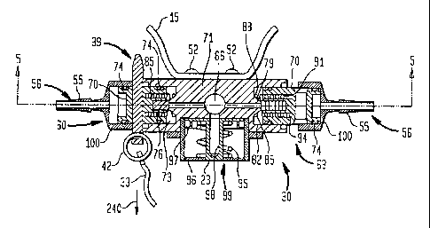
L'invention concerne un ensemble collecteur de soupape (30) possédant un corps de soupape (71) avec au moins une chambre (73) définie dans ce corps de soupape. La chambre (73) possède au moins un orifice d'entrée et au moins un orifice de sortie, ainsi qu'au moins une ouverture. Un clapet (70) est placé dans la chambre (73). Le clapet (70) coulisse dans la chambre (73) entre une première position dans laquelle il ferme l'orifice d'entrée et une seconde position dans laquelle il est espacé de l'orifice d'entrée. Le clapet (70) possède une ouverture (57). Une goupille (39) possédant une première section d'un premier diamètre et une seconde section d'un second diamètre peut être placée de façon coulissante à travers la ou les ouvertures situées dans le corps de soupape (71) et à travers l'ouverture (57) située dans le clapet (70).


Abrégé anglais


A valve manifold assembly (30) having a valve body (71) with at least one
chamber (73) defined therein. The chamber (73) has at least one inlet and at
least one outlet and has at least one opening. A poppet (70) is disposed in
the chamber (73). The poppet (70) slides in the chamber (73) between a first
position where the poppet seals the inlet and a second position where the
poppet is disposed in spaced-apart relation relative to the inlet. The poppet
(70) has an opening (57) disposed therein. A pin (39) having a first section
with a first diameter and having a second section with a second diameter is
capable of being slidably disposed through the at least one opening in the
valve body (71) and through the opening (57) in the poppet (70).

Revendications

Note : Les revendications sont présentées dans la langue officielle dans laquelle elles ont été soumises.


-13-
CLAIMS:
1. A valve manifold assembly, comprising:
a valve body having at least one chamber defined therein, the chamber having
at least one
inlet and at least one outlet, the valve body having a first opening and a
second opening;
a poppet disposed in the chamber, the poppet slidably disposed in the chamber
between a
first position where the poppet seals the inlet and a second position where
the poppet is disposed
in spaced apart relation relative to the inlet, the poppet having at least one
opening disposed
therein; and,
a pin capable of being slidably disposed through the first opening in the
valve body, the
at least one opening in the poppet and through the second opening in the valve
body.
2. A valve manifold assembly, comprising:
a valve body having at least one chamber defined therein, the chamber having
at least one
inlet and at least one outlet and having at least one opening;
a poppet disposed in the chamber, the poppet slidably disposed in the chamber
between a
first position where the poppet seals the inlet and a second position where
the poppet is disposed
in spaced apart relation relative to the inlet, the poppet having an opening
disposed therein; and,
a pin capable of being slidably disposed through the at least one opening in
the valve
body and through the at least one opening in the poppet, wherein the pin has a
first section with a
first diameter and having a second section with a second diameter.
3. The valve manifold assembly of claim 2, wherein the first section on the
pin is disposed
along a midportion.
4. The valve manifold assembly of claim 2, wherein the second section of the
pin is
disposed on opposite sides of the first section.
5. The valve manifold assembly of claim 2, wherein the first diameter is
larger than the
second diameter.

-14-
6. A valve manifold assembly, comprising:
a valve body having at least one chamber defined therein, the chamber having
at least one
inlet and at least one outlet and having at least one opening;
a poppet disposed in the chamber, the poppet slidably disposed in the chamber
between a
first position where the poppet seals the inlet and a second position where
the poppet is disposed
in spaced apart relation relative to the inlet, the poppet having an opening
disposed therein; and,
a pin capable of being slidably disposed through the at least one opening in
the valve
body and through the at least one opening in the poppet, wherein the at least
one opening in the
valve body further comprises a first and second opening in the valve body
formed in the shape of
a slot such that the poppet and pin are capable of rotating relative to the
valve body.
7. A valve manifold assembly, comprising:
a valve body having at least one chamber defined therein, the chamber having
at least one
inlet and at least one outlet and having a first opening and a second opening;
a poppet disposed in the chamber, the poppet slidably disposed in the chamber
between a
first position where the poppet seals the inlet and a second position where
the poppet is disposed
in spaced apart relation relative to the inlet, the poppet having at least one
opening disposed
therein; and,
a pin capable of being slidably disposed through the first opening in the
valve body and
through the at least one opening in the poppet, and through the second opening
in the valve body,
wherein the pin is attached to at least one lanyard disposed on at least one
oxygen mask
assembly.
8. The valve manifold assembly of claim 2, further comprising a transition
zone disposed
between the first and second section.
9. The valve manifold assembly of claim 8, wherein the transition zone has a
gradually
varying diameter.
10. A valve manifold assembly, comprising:
a valve body having at least one chamber defined therein, the chamber having
at least one

-15-
inlet and at least one outlet, the valve body having a first opening and a
second opening;
a poppet disposed in the chamber, the poppet slidably disposed in the chamber
between a
first position where the poppet seals the inlet and a second position where
the poppet is disposed
in spaced apart relation relative to the inlet, the poppet having at least one
opening disposed
therein; and,
a pin capable of being slidably disposed through the first opening in the
valve body,
through the at least one opening in the poppet, and through the second opening
in the valve body,
wherein, the poppet is biased in the open position.
11. A valve manifold assembly for an oxygen mask dispensing container, the
valve manifold
assembly, comprising:
a valve body having at least one chamber defined therein, the chamber having
at least one
inlet and at least one outlet, the valve body having a first opening and a
second opening;
a poppet disposed in the chamber, the poppet slidably disposed in the chamber
between a
first position where the poppet seals the inlet and a second position where
the poppet is disposed
in spaced apart relation to the inlet, the poppet having at least one opening
disposed therein;
a pin capable of being slidably disposed through the first opening in the
valve body,
through the opening in the poppet and through the second opening in the valve
body;
at least one lanyard attached to the pin at a first end and having a second
end disposed
opposite the first end; and,
at least one oxygen mask assembly connected to the second end of the at least
one
lanyard and disposed in fluid communication with the outlet of the chamber.
12. A valve manifold assembly for an oxygen mask dispensing container, the
valve manifold
assembly, comprising:
a valve body having at least one chamber defined therein, the chamber having
at least one
inlet and at least one outlet and having at least one opening;
a poppet disposed in the chamber, the poppet slidably disposed in the chamber
between a
first position where the poppet seals the inlet and a second position where
the poppet is disposed
in spaced apart relation to the inlet, the poppet having an opening disposed
therein;
a pin capable of being slidably disposed through the at least one opening in
the valve

-16-
body and through the opening in the poppet;
at least one lanyard attached to the pin at a first end and having a second
end disposed
opposite the first end; and,
at least one oxygen mask assembly connected to the second end of the at least
one
lanyard and disposed in fluid communication with the outlet of the chamber,
wherein the pin has
a first section with a first diameter and having a second section with a
second diameter.
13. The valve manifold assembly of claim 12, wherein the first section on the
pin is disposed
along a midportion.
14. The valve manifold assembly of claim 12, wherein the second section of the
pin is
disposed on opposite sides of the first section.
15. The valve manifold assembly of claim 12, wherein the first diameter is
larger than the
second diameter.
16. A valve manifold assembly for an oxygen mask dispensing container, the
valve manifold
assembly, comprising:
a valve body having at least one chamber defined therein, the chamber having
at least one
inlet and at least one outlet and having at least one opening;
a poppet disposed in the chamber, the poppet slidably disposed in the chamber
between a
first position where the poppet seals the inlet and a second position where
the poppet is disposed
in spaced apart relation to the inlet, the poppet having an opening disposed
therein;
a pin capable of being slidably disposed through the at least one opening in
the valve
body and through the opening in the poppet;
at least one lanyard attached to the pin at a first end and having a second
end disposed
opposite the first end; and,
at least one oxygen mask assembly connected to the second end of the at least
one
lanyard and disposed in fluid communication with the outlet of the chamber,
wherein the at least
one opening in the valve body further comprises a first and second opening in
the valve body
formed in the shape of a slot such that the poppet and pin are capable of
rotating relative to the

-17-
valve body.
17. The valve manifold assembly of claim 11, wherein the at least one lanyard
is attached to
a conduit that leads to the at least one oxygen mask assembly.
18. The valve manifold assembly of claim 12, further comprising a transition
zone disposed
between the first and second section.
19. The valve manifold assembly of claim 18, wherein the transition zone has a
gradually
varying diameter.
20. The valve manifold assembly of claim 11, wherein the poppet is biased in
the open
position.
21. The valve manifold assembly of claim 20, wherein the poppet is biased by a
coil spring.
22. A valve manifold assembly for an oxygen mask dispensing container, the
valve manifold
assembly, comprising:
a valve body having at least one chamber defined therein, the chamber having
at least one
inlet and at least one outlet, the valve body having a first opening and a
second opening;
a poppet disposed in the chamber, the poppet slidably disposed in the chamber
between a
first position where the poppet seals the inlet and a second position where
the poppet is disposed
in spaced apart relation to the inlet, the poppet having at least one opening
disposed therein;
a door capable of opening automatically in response to the flow of breathing
gas into the
valve body; and,
a pin capable of being slidably disposed through the first opening in the
valve body, the
at least one opening in the poppet, and through the second opening in the
valve body, the pin
having at least one end disposed adjacent to the door, such that when the door
is in a closed
position the door obstructs movement of the pin.

Description

Note : Les descriptions sont présentées dans la langue officielle dans laquelle elles ont été soumises.


CA 02472525 2007-06-01
1
VALVE MANIFOLD ASSEMBLY
FIELD OF THE INVENTION
The invention relates to an assembly for deploying an
emergency breathing mask in an aircraft.
BACKGROUND OF THE INVENTION
Many aircraft are required to provide passengers and
crew members in the pressurized cabin with an emergency
breathing mask in the event of a sudden loss of cabin pressure
due to a rupture in the cabin wall or to a failure in the aircraft's
pressurizing system. The conventional emergency breathing
mask is typically stowed in an overhead storage container directly
over the user. Upon a sudden loss of cabin pressure, the container
door automatically opens and the mask is deployed by gravity
to the user. The mask typically hangs from the open container
in the vicinity of the user, but the flow of breathing gas to the
mask is not automatically activated. Because the mask may
drop over an empty seat, it is desirable to have a user-activated
valve that controls the flow of breathing gas to the mask. It has
been known to provide a lanyard that is connected between
the breathing gas conduit or the mask and a valve in the
container such that when the mask is pulled toward the face
of the user, the tension on the lanyard opens a valve to allow
breathing gas to flow to the mask. An

CA 02472525 2007-06-01
2
example is disclosed in U.S. Patent No. 4,909,247.
What is needed is an improved valve manifold assembly.
SUMMARY OF THE INVENTION
The present invention meets the above need by providing a
valve manifold assembly having a valve body with at least one
chamber defined therein. The chamber has at least one inlet and
at least one outlet and has at least one opening. A poppet is
disposed in the chamber. The poppet slides in the chamber between
a first position where the poppet seals the inlet and a second
position where the poppet is disposed in spaced-apart relation relative
to the inlet. The poppet has a bore disposed therethrough. A pin
is capable of being slidably disposed through the at least one
opening in the valve body and through the bore in the poppet.
The pin may take different shapes to avoid unintentional
actuation of the valve due to environmental conditions such as shock
or vibration. In a first embodiment, the pin has at least two concentric
sections having different diameters. In a second embodiment, the
pin is elongated such that it is prevented from exiting the poppet due
to the position of the door when the door is in the closed position.
BRIEF DESCRIPTION OF THE DRAWINGS
The invention is illustrated in the drawings in which like
reference characters designate the same or similar parts throughout
the figures of which:
FIG. 1 is a fragmentary longitudinal schematic view

CA 02472525 2004-07-02
WO 2003/057562 PCT/US2003/000221
- 3 -
of the interior of an airplane showing one environment in
which the invention is operative;
Fig. 2 is a partial front elevational view of an
aircraft passenger oxygen system in the'deployed
position;
Fig. 3 is a top view of the valve manifold assembly
of the present invention;
Fig. 4 is a cross-sectional view taken along lines
4-4 of Fig. 3;
Fig. 5 is a cross-sectional view taken along lines
5-5 of Fig. 4;
Fig. 6 is a side elevational view of the pin of the
present invention;
Fig. 7 is an end view taken along lines 7-7 of Fig.
6; and,
Fig. 8 is a sectional view of an alternate
embodiment of the present invention.
DETAILED DESCRIPTION
In an embodiment of the invention chosen for the
purpose of illustration there i.s shown by way of example
a fragment of aircraft frame 10 having a floor 11 on
which are rows of seats 12 and 13. A ceiling panel 14
has mounted in it over each respective row of seats an
oxygen mask dispensing container indicated generally by
the reference character 15, all of which are supplied
from a common oxygen source 16 through,an oxygen line 17
having a pressure control valve 18. By way of example,
the passenger mask unit on the left is shown in released
position and that on the right in closed position. Each
mask 21 is provided with a conduit 24 for oxygen attached

CA 02472525 2004-07-02
WO 2003/057562 PCT/US2003/000221
- 4 -
to a valve manifold assembly 30 (Figs. 3-5) and a lanyard
33.
Turning to Fig. 2, as an example two masks 21 are
sha,wn in the deployed position. The number of masks 21
may be varied as will become obvious to those of ordinary
skill in the art. As shown a door 22 operis from ceiling
panel 14. to deploy the masks 21. As described in greater
detail hereinafter, the door 22 may be automatically
opened by means of a spring-biased piston 23 (Fig. 4)
engaging with a latch 26 on the inside surface of the
door 22. The masks 21 are shown in a fully downwardly
deployed position within reach of the user. When the
door 22 is opened as shown in Fig. 2, the free fall of
the masks 21 is stopped by lanyards 33 which connect
between the conduit 24 at 36 and control pins 39 (Fig. 4)
on valve manifold assembly 30. The lanyards 33 may be
attached at one end to the conduit 24 as shown or they
can be attached at other points on the conduit 24 or mask
21. The lanyards 33 can be attached at any point on the
conduit 24 or mask 21 that provides significant motion
when the mask 21 is drawn to the face of the user during
deployment. The lanyards 33 are connected to pins 39 by
eyelets 42 (Fig. 4) that are attached to the pin 39
through opening 32 (Fig. 6). Lanyards 33 thus support
masks 21 within reach of intended users and in this
position hang taut under the weight of the masks 21 while
conduits 24 remain slack as illustrated at 45 in Fig. 2.
Traction on lanyard 33, as by positive action of an
individual user pulling downward on one of the masks 21,
withdraws pin 39 from valve manifold assembly 30 to
actuate the supply of breathing gas to that mask 21. In

CA 02472525 2004-07-02
WO 2003/057562 PCT/US2003/000221
- 5 -
the illustrated form, each mask 21 is of the modified
phase dilution type comprising a truncated hollow cone 31
of suitable material, such as an elastomer, open through
its larger end which is adapted to be held against the
face of a user and kept in place by an elastic band 34.
The smaller end 35 of each mask 21 is connected to a
reservoir bag 37 which is connected to conduit 24 whereby
breathing fluid is provided through conduit 24 into the
bag to accumulate flow when the user is not inhaling.
Attached at the smaller end 35 of the mask 21 are three
flapper valves (not shown). One flapper valve is spring
loaded to be a phase dilution valve which allows a
predetermined amount of outside air into the mask 21 to
mix with the breathing fluid supplied to the user so that
each user will receive a metered amount of fluid.
Another flapper valve is an exhalation valve assembly
through which the exhaled carbon dioxide from the user is
dispensed to the surrounding atmosphere. The third
flapper valve permits fluid flow from the reservoir bag
37 to mask 21 and closes to prevent reverse flow. Such
mask arrangements are known in the art, and are not per
se, a part of this invention. Other face masks 21,
including masks equipped with demand regulators can be
utilized in the present invention.
Turning to Fig. 3, the valve manifold assembly 30
has a set of openings 50 disposed in the top of the
assembly 30. The openings 50 may be threaded to engage
with a set of fasteners 52 (shown in Fig. 4) that attach
the assembly 30 to the oxygen mask dispensing container
15. Hose connectors 56 extend from opposite sides of the
assembly 30. The connectors 56 showft are in the form of,

CA 02472525 2007-06-01
6
hose barbs 55 for connection to the conduits 24 that carry the
breathing gas to the masks 21. Other types and shapes of hose
connectors would also be suitable. For example, as will be evident
to those of ordinary skill in the art, additional hose connectors 56
may be connected to the flow actuation valve 60 so that a single
flow actuation valve can distribute breathing gas to a plurality of
masks 21 through a plurality of conduits 24. As will also be evident
to those of ordinary skill in the art, if multiple masks 21 are supplied
through a single flow actuation valve then the respective lanyards
33 would each be connected to a single pin 39. Accordingly, the
present invention may function with a flow actuation valve for every
mask or may function with multiple masks connected to a single
flow actuation valve. When multiple masks 21 are connected to a
single flow actuation valve, breathing gas may be allowed to flow
to a mask deployed over an empty seat.
As will be described in greater detail hereinafter, the valve
manifold assembly 30 is formed by attaching valve housings 100
to opposite sides of valve body 71 by means of screws 401.
The valve housing 100 has a slot 300 that allows for rotation of
the pin 39 in unison with the poppet 70. The opening 57 in the
poppet 70 that receives the pin 39 visible through the slot 300.
In FIG. 4, the lanyards 33 are connected to pins 39 by eyelets
42. On the left hand side of the figure, a first flow actuation valve
60 is shown in the closed position. On the right hand side of
the figure a second flow actuation valve 63 (which is identical
to the first flow actuation valve 60) is shown in the open position

CA 02472525 2004-07-02
WO 2003/057562 PCT/US2003/000221
- 7 -
where the pin 39 has been removed by the user pulled
lanyard 33. A pair of ports 66 (best shown in Fig. 5)
provide for pressurizing the manifold from the breathing
gas source. Two ports 66 are provided in the manifold,
therefore numerous manifold assemblies 30 can be
connected in series so that outlets 56 are in parallel to
accommodate specific applications. Multiple assemblies
30 may be connected in series or a single assembly 30 may
be constructed with additional flow actuation valves'.
One manifold port 66 can be plugged while the other is
supplied with gas under pressure.
The flow actuation valve 60 is comprised of a
precision machined poppet 70 that may be constructed out
of suitable materials such as aluminum. The poppet 70
moves back and forth inside a chamber 73 disposed inside
the valve body 71. A set of 0-rings 74 seals the sides'
of the poppet 70 inside the chamber 73 so that breathing
gas cannot flow around the sides of the poppet 70. At
one end of the poppet 70, a soft elastomer seat 76 is
inserted into a bore in the poppet 70 and retained in
place with an adhesive. The bore is deep enough to
provide a sufficient amount of space for the elastomer as
described hereafter. The soft elastomer may comprise a
silicone meeting or exceeding MIL ZZ-R-765 Type IIA or
IIB Grade 70. The adhesive may comprise a cyanoacrylate,
silicone, or other suitable adhesive. A hard seat 79 is
formed around a centrally disposed opening 82 in the
valve body 71.
A coil spring 85 has a first end 88 and a second end
91. The first end 88 engages with the valve body 71
around the opening 82. The second end 91 is disposed

CA 02472525 2007-06-01
8
opposite the first end 88 and rests inside an opening 94 in the
poppet 70. Depending on the spring rate, the spring 85 could also be
disposed external to the poppet 70. The spring 85 may be formed
out of stainless steel. The spring 85 biases the poppet in the open position
shown on the right hand side of FIG. 4.
In order to assemble the flow actuation valve 60, 63, the
Valve spring 85 is inserted into the chamber 73 formed in the valve body
71 such that the poppet 70 acts to compress the spring 85 as it is inserted.
The portion of the poppet 70 extending beyond the valve body 71
Is inserted into the valve housing 100. The valve housing 100 is
Secured to the valve body 71 using screws 401 (FIG. 5) to form the valve
manifold assembly 30.
Upon inserting the pin 39 through the poppet 70, the poppet
70 and the soft seat 76 are forced toward the hard seat 79 while
compressing the valve spring 85. At full insertion of the pin 39, the
compression forces the soft seat 76 to conform to the hard seat 79
thereby providing a seal. Also, when the pin 39 is inserted into the
poppet 70 as shown in the left hand side of FIG. 4, force is exerted by
the spring 85 onto the pin 39 through the poppet 70 causing it to rest
against the valve housing 100.
In the middle of FIG. 4, a spring-biased piston 23 is shown.
The spring 95 may be a coil spring disposed around the piston 23
and biased in the closed position as shown in FIG. 4. The piston
23 is held inside a housing 96 that attaches to the assembly 30.
The piston 23 has a set of 0-rings 97 for sealing the piston inside
the housing 96. The inside of piston 23 is hollow such that

CA 02472525 2004-07-02
WO 2003/057562 PCT/US2003/000221
9
a pressurized breathing gas from port 66 acts against the
inside surface 98 of the piston 23 to move the piston 23
downward, with respect to the orientation of Fig. 4,
against the force of spring 95. When actuated by
pressure, the piston 23 extends out of the opening 99 in
the housing 96 and engages with the door latch 26 to
release the door 22 as shown in Fig. 2.
Turning to Fig. 5, the arrows 101 indicate the flow
path of the breathing gas through the right hand side of
the figure. The removal of the pin 39 results in the
poppet 70 moving to the right with respect to the
orientation of the figure. The force of the spring 85
(and supplemented by the gas pressure) causes this
movement of the poppet 70. As a result of this motion,
the soft seat 76 on the poppet 70 moves away from the
central opening 82 in the valve body 71. Accordingly, '
referring to the right hand side of the figure, the
breathing gas from the one or more open ports 66 is
allowed to pass through the central opening 82 and into
the chamber 73 formed between the left side of the poppet
70 and the inside walls 102 of the valve body 71.
Because the poppet 70 has 0-rings 74 installed around its
perimeter, the breathing gas cannot escape between the
inside walls 102 of the valve body 71 and the poppet 70.
A pair of pathways 103 disposed through the poppet 70
provide for egress of the pressurized gases. As shown,
there are two channels disposed through the poppet 70.
Each channel has a first open end on the left side of the
poppet 70 and has a second open end at the right hand
side of the poppet 70. The second opening allows
breathing gas under pressure to pass through the poppet

CA 02472525 2004-07-02
WO 2003/057562 PCT/US2003/000221
- 10 -
70 into the chamber 110 formed between the poppet 70 and
the valve housing 100. The valve housing 100 also has a
central opening 112 that extends through the hose
connector 56. The breathing conduit 24 that leads to the
mask 21 is attached to the hose connector 56 and carries
the breathing gas to the mask 21 as shown in Fig. 2.
Returning to Fig. 5, a calibrated orifice 113 is
fabricated in the hose barb area of the connector 56 of
the valve housing 100, so that a predetermined flow of
oxygen is administered to the oxygen mask 21 at a given
supply pressure.
In Figs. 6 and 7, the pin 39 is shown in greater
detail. The pin 39 has two sections with different but
concentric diameters. The first diameter 200 which is
the larger of the two diameters is located along a
midportion 210 of the pin 39, while the second diameter
220 which is the smaller of the two diameters extends
along end portions 215 disposed on opposite sides of the
mid portion 210. A transition zone 225 of varying
diameter is located at both locations where the pin 39
changes diameters. When the pin 39 is fully inserted,
the section having the first diameter 200 is acted on by
the compressed valve spring 85 through the poppet 70,
thereby causing the section with the smaller pin diameter
220 to rest against the opening in the valve housing 100.
When the pin 39 is removed in the direction indicated by
arrow 240 in Fig. 4 and with reference to the opening in
the valve housing 100 located closer to the eyelet 42,
the section with the smaller diameter 220 passes against
the valve housing 100 until the first transition zone 225
of varying diameter comes in contact'with the valve

CA 02472525 2004-07-02
WO 2003/057562 PCT/US2003/000221
- 11 -
housing 100. As the transition zone 225 of the pin 39
passes through the opening in the valve housing 100, the
valve spring 85 is further compressed through the force
of the pin 39 on the poppet 70. The valve spring 85
compression continues until it reaches the maximum that
is defined as one-half of the diametrical difference
between the two diameters 200, 220 of the pin 39. This
additional compression of the valve spring 85 increases
the amount of force required to remove the pin 39. The
additional force required to remove the pin 39 is
provided to prevent pin 39 from being inadvertently
removed due to environmental conditions such as shock and
vibration. The soft seat 79 material must be
sufficiently resilient to maintain a seal at both levels
of compression forces corresponding to the different
diameters 200, 220 and to do so without resulting in
compression set. The depth of the bore may be increased
in order to provide for a greater amount of the elastomer
to be utilized in order to prevent compression set.
In Fig. 8, an alternate embodiment of the invention
includes a pin 339 having a constant diameter throughout
a majority of its length. The pin 339 is elongated such
that inadvertent removal of the pin 339 from the poppet
70 is prevented because the pin 339 extends downward far
enough toward the door 22 such that the pin 339 is
obstructed by the door 22 when the door 22 is in its
closed position. When.the door 22 opens as shown in Fig.
2, the masks 21 drop down and the pin 339 can be removed
from the poppet 70 via the user pulled lanyard 33 as
described previously.
Returning to Fig. 4, the pin 39 extends through the

CA 02472525 2004-07-02
WO 2003/057562 PCT/US2003/000221
- 12 -
poppet 70 and completeiy tnrough the valve assembly 30.
As will be evident to those of ordinary skill in the art,
the poppet 70 may be provided with a recess for receiving
a pin that does not extend all the way through the valve
assembly 30. Also, it will be evident to those of
ordinary skill in the art that the movable member does
not have to be solid and could be hollow.
While the invention has been described in connection
with certain embodiments related to a passenger oxygen
system for aircraft, it is not intended to limit the
scope of the invention to the particular forms set forth,
but, on the contrary, it is intended to cover such
alternatives, modifications, and equivalents as may be
included within the spirit and scope of the invention.
In particular, the valve manifold assembly 30 of the
present invention may be useful in other shutoff or gas
valve applications. Accordingly, the invention is not to
be limited to the particular application to a passenger
oxygen delivery system in an aircratt. Other
applications of the device to shut off valves will be
known to those of ordinary skill in the art.

Dessin représentatif
Une figure unique qui représente un dessin illustrant l'invention.
États administratifs

2024-08-01 : Dans le cadre de la transition vers les Brevets de nouvelle génération (BNG), la base de données sur les brevets canadiens (BDBC) contient désormais un Historique d'événement plus détaillé, qui reproduit le Journal des événements de notre nouvelle solution interne.

Veuillez noter que les événements débutant par « Inactive : » se réfèrent à des événements qui ne sont plus utilisés dans notre nouvelle solution interne.

Pour une meilleure compréhension de l'état de la demande ou brevet qui figure sur cette page, la rubrique Mise en garde , et les descriptions de Brevet , Historique d'événement , Taxes périodiques et Historique des paiements devraient être consultées.

Historique d'événement

Description Date
Le délai pour l'annulation est expiré 2011-01-06
Lettre envoyée 2010-01-06
Inactive : TME en retard traitée 2009-02-04
Inactive : Paiement - Taxe insuffisante 2009-01-28
Lettre envoyée 2009-01-06
Accordé par délivrance 2008-10-07
Inactive : Page couverture publiée 2008-10-06
Lettre envoyée 2008-08-04
Exigences de modification après acceptation - jugée conforme 2008-08-04
Modification après acceptation reçue 2008-07-22
Préoctroi 2008-07-22
Inactive : Taxe finale reçue 2008-07-22
Un avis d'acceptation est envoyé 2008-02-21
Inactive : Lettre officielle 2008-02-21
Inactive : Correspondance - Poursuite 2008-02-21
Lettre envoyée 2008-02-21
Un avis d'acceptation est envoyé 2008-02-21
Inactive : Approuvée aux fins d'acceptation (AFA) 2007-12-14
Modification reçue - modification volontaire 2007-06-01
Inactive : Dem. de l'examinateur par.30(2) Règles 2006-12-04
Inactive : CIB de MCD 2006-03-12
Inactive : IPRP reçu 2005-03-04
Lettre envoyée 2005-01-24
Lettre envoyée 2004-12-07
Inactive : CIB en 1re position 2004-11-10
Inactive : CIB attribuée 2004-11-10
Modification reçue - modification volontaire 2004-10-19
Lettre envoyée 2004-10-04
Toutes les exigences pour l'examen - jugée conforme 2004-09-24
Exigences pour une requête d'examen - jugée conforme 2004-09-24
Requête d'examen reçue 2004-09-24
Inactive : Lettre de courtoisie - Preuve 2004-09-14
Lettre envoyée 2004-09-14
Inactive : Page couverture publiée 2004-09-14
Inactive : Notice - Entrée phase nat. - Pas de RE 2004-09-09
Demande reçue - PCT 2004-08-04
Inactive : Transfert individuel 2004-07-26
Exigences pour l'entrée dans la phase nationale - jugée conforme 2004-07-02
Demande publiée (accessible au public) 2003-07-17

Historique d'abandonnement

Il n'y a pas d'historique d'abandonnement

Taxes périodiques

Le dernier paiement a été reçu le 2007-12-18

Avis : Si le paiement en totalité n'a pas été reçu au plus tard à la date indiquée, une taxe supplémentaire peut être imposée, soit une des taxes suivantes :

  • taxe de rétablissement ;
  • taxe pour paiement en souffrance ; ou
  • taxe additionnelle pour le renversement d'une péremption réputée.

Les taxes sur les brevets sont ajustées au 1er janvier de chaque année. Les montants ci-dessus sont les montants actuels s'ils sont reçus au plus tard le 31 décembre de l'année en cours.
Veuillez vous référer à la page web des taxes sur les brevets de l'OPIC pour voir tous les montants actuels des taxes.

Titulaires au dossier

Les titulaires actuels et antérieures au dossier sont affichés en ordre alphabétique.

Titulaires actuels au dossier
AVOX SYSTEMS INC.
Titulaires antérieures au dossier
DENNIS P. PIETRANTONI
Les propriétaires antérieurs qui ne figurent pas dans la liste des « Propriétaires au dossier » apparaîtront dans d'autres documents au dossier.
Documents

Pour visionner les fichiers sélectionnés, entrer le code reCAPTCHA :


Pour visualiser une image, cliquer sur un lien dans la colonne description du document. Pour télécharger l'image (les images), cliquer l'une ou plusieurs cases à cocher dans la première colonne et ensuite cliquer sur le bouton "Télécharger sélection en format PDF (archive Zip)" ou le bouton "Télécharger sélection (en un fichier PDF fusionné)".

Liste des documents de brevet publiés et non publiés sur la BDBC .

Si vous avez des difficultés à accéder au contenu, veuillez communiquer avec le Centre de services à la clientèle au 1-866-997-1936, ou envoyer un courriel au Centre de service à la clientèle de l'OPIC.


Description du
Document 
Date
(aaaa-mm-jj) 
Nombre de pages   Taille de l'image (Ko) 
Description 2004-07-01 12 540
Abrégé 2004-07-01 2 72
Revendications 2004-07-01 5 155
Dessins 2004-07-01 4 91
Dessin représentatif 2004-09-13 1 20
Description 2007-05-31 12 493
Revendications 2007-05-31 5 220
Dessins 2007-05-31 4 76
Revendications 2008-07-21 5 228
Dessin représentatif 2008-09-23 1 16
Accusé de réception de la requête d'examen 2004-10-03 1 185
Rappel de taxe de maintien due 2004-09-08 1 110
Avis d'entree dans la phase nationale 2004-09-08 1 201
Courtoisie - Certificat d'enregistrement (document(s) connexe(s)) 2004-09-13 1 129
Courtoisie - Certificat d'enregistrement (document(s) connexe(s)) 2004-12-06 1 106
Avis du commissaire - Demande jugée acceptable 2008-02-20 1 164
Avis de paiement insuffisant pour taxe (anglais) 2009-01-27 1 91
Avis concernant la taxe de maintien 2009-01-27 1 171
Quittance d'un paiement en retard 2009-02-24 1 164
Avis concernant la taxe de maintien 2010-02-16 1 170
PCT 2004-07-01 4 140
Correspondance 2004-12-06 1 17
Correspondance 2005-01-23 1 19
Taxes 2004-12-21 1 27
PCT 2004-07-02 6 230
Taxes 2005-12-19 1 26
Taxes 2006-12-13 1 28
Taxes 2007-12-17 1 28
Correspondance 2008-02-25 1 13
Correspondance 2008-07-21 2 58
Taxes 2009-01-06 2 53
Taxes 2009-02-03 1 32