Note : Les descriptions sont présentées dans la langue officielle dans laquelle elles ont été soumises.
CA 02472845 2004-07-02
INFLATION VALVE ASSEMBLY FOR.A DiTNNAGE OR CARGO AIR BAG
FIELD OF THE INVENTION
The present invention relates generally to dunnage
air bags, and more particularly to a new and improved infla-
tion valve assembly for facilitating the inflation of an in-
flatable bladder disposed interiorly of, or comprising, a
dunnage air bag for use in connection with securing or brac-
ing cargo within the holds of, for example, railroad cars,
airplanes, ships, truck trailers, and the like.
BACKGROUND OF THE INVENTION
Cargo or dunnage air bags are used within the cargo
shipment or transportation industry as a means for readily
and easily securing or bracing cargo within the holds of, for
example, railroad cars, ships, airplanes, truck trailers, and
the like. Such dunnage or cargo air bags conventionally com-
prise an inflatable bladder which is enclosed within an outer
bag or envelope which is conventionally fabricated from a
plurality of paper plies. The air bags are conventionally of
such construction and size as to readily enable the same to
CA 02472845 2004-07-02
be inserted into voids or spaces defined between spaced
loads, or between a particular cargo load and a side or end
wall of the cargo container or hold, whereupon inflation of
the air bag, the air bag will expand thereby fixedly engaging
the adjacent cargo loads, or the cargo load and container
wall, so as to secure the cargo loads against undesirable
movement during transit. Obviously, in order to achieve the
inflation of the cargo or dunnage air bags to a predetermined
pressurized level, such air bags are also conventionally pro-
vided with an inflation valve assembly so as to permit pres-
surized air or compressed air to be conducted into the inter-
ior portion of the inflatable bladder so as to inflate the
same, or to permit the pressurized air or compressed air, al-
ready disposed within the inflated bladder, to be conducted
out from the interior portion of the inflatable bladder so as
to deflate the same.
A first conventional PRIOR ART inflation valve as-
sembly is disclosed, for example, within FIGURE 1 which sub-
stantially corresponds to the inflation valve assembly por-
tion of FIGURE 2 as illustrated within United States Patent
5,042,541 which issued to Krier et al. on August 27, 1991,
and it is seen that this inflation valve assembly utilizes a
spring-biased valve stem mechanism. More particularly, as can
be readily appreciated from FIGURE 1, a cargo air bag is gen-
erally indicated by the reference character 10 and is seen to
comprise a paper bag 11 and an inflatable bladder 62. The in-
flation valve assembly is generally indicated by the refer-
ence character 12 and is seen to comprise a tubular valve
body 56 defining a hollow space 57 therewithin, and an annu-
lar flange portion 60 integrally fixed thereto. The tubular
2
CA 02472845 2004-07-02
valve body 56 is adapted to be inserted through an aperture
defined within a wall 58 of the cargo air bag 10 such that
the free distal end 80 of the valve body 56 projects outward-
ly from the cargo air bag 10 so as to be externally access-
ible for fluidic communication with a suitable air inflation
fixture or assembly by means of which the compressed or pres-
surized air can be conducted into the interior portion of the
inflatable bladder 62. An external annular shoulder portion
66 of the valve body 56 engages an outer surface of the air
bag 10, while the annular flange portion 60 is adapted to be
ultrasonically welded to an interior wall portion of the in-
flatable bladder 62 so as to form an air-tight seal there-
with.
The inflation valve assembly 12 also comprises a
valve stem 70 which extends through the hollow space 57 of
the valve body 56. A closure plate 72 is disposed upon a
first end of the valve stem 70, and a spring member 76 is
interposed between an internal shoulder portion of the valve
body 56 and a second opposite end 78 of the valve stem 70. An
annular valve seat 64 is defined upon an interior portion of
the valve body 56, and an annular ridge 74 is defined upon
the closure plate 72. Accordingly, the spring member 76 norm-
ally biases the closure plate 72 and its annular ridge 74 on-
to the valve seat 64 such that the inflation valve assembly
12 may be disposed in a first CLOSED position or state where-
by pressurized air or compressed air cannot be conducted into
the interior of the inflatable bladder 62, or alternatively,
pressurized air or compressed air, already contained within
the inflated bladder 62, is not permitted to escape from the
inflated bladder 62. Conversely, when a force is imposed upon
3
CA 02472845 2004-07-02
the free end portion 78 of the valve stem 70, the valve stem
70 is axially moved against the biasing force of spring mem-
ber 76 such that the closure plate 72 and its annular ridge.
74 are moved away from the valve seat 64 such that the infla-
tion valve assembly 12 may be disposed in a second OPENED po-
sition or state whereby pressurized air or compressed air can
be conducted into the interior of the inflatable bladder 62,
or alternatively, pressurized air or compressed air already
contained within the inflated bladder 62 is permitted to es-
cape from the inflated bladder 62.
In lieu of the spring-biased valve stem mechanism
as disclosed within Krier et al., the inflation valve assem-
bly may alternatively comprise a flapper valve member which
is mounted upon the inner end portion of a tubular valve body
so as to likewise be movable between, for example, a first
CLOSED position or state, either by means of the inherent re-
siliency of, for example, a living hinge structure, or as a
result of being biased to the CLOSED position or state by
means of the internal pressure within the inflatable bladder
when the interior portion of the inflatable bladder has actu-
ally been pressurized, whereby the internal pressurized air
is able to be effectively and sufficiently retained within
the interior of the inflatable bladder of the dunnage or car-
go air bag until, for example, an external closure cap is
able to be threadedly engaged upon the inflation valve assem-
bly so as to effectively close and seal the inflation valve
assembly, and a second OPEN state or position as a result of,
for example, being manually manipulated whereby the flapper
valve member is able to effectively be moved away from its
valve seat formed upon a nipple portion of the inflation
4
CA 02472845 2004-07-02
valve assembly so as to permit an inflation nozzle to be flu-
idically mated therewith whereby pressurized air or compress-
ed can be introduced into the interior of the inflatable
bladder of the dunnage or cargo air bag. A second convention-
al PRIOR ART inflation valve assembly, comprising a flapper
valve member, is disclosed, for example, within FIGURES 2-4
and is generally indicated by means of the reference charact-
er 10.
More particularly, with reference being made to
FIGURES 2-4, it is seen that the second conventional PRIOR
ART inflation valve assembly 10 comprises an annular flange
member 12 wherein, for example, the undersurface portion 14
of the annular flange member 12 is adapted to be heat-sealed
to an interior surface portion of the inflatable bladder
while an externally threaded nipple portion 16 of the infla-
tion valve assembly 10 is adapted to project outwardly
through means of a suitable aperture formed within the ply of
the inflatable bladder, as well as suitable apertures formed
within the one or more paper plies comprising the dunnage or
cargo air bag. In this manner, when a suitable inflation noz-
zle, not shown, is fluidically connected to the nipple por-
tion 16 of the inflation valve assembly 10, pressurized air
or compressed air can be conducted into the interior of the
inflatable bladder so as to inflate the same. In addition to
the aforenoted structure, characteristic of the second con-
ventional PRIOR ART inflation valve assembly 10, it is fur-
ther seen that the second conventional PRIOR ART inflation
valve assembly 10 also has an annular upstanding ring member
18 integrally disposed upon the upper surface portion 20 of
the annular flange member 12. As can best be appreciated from
5
CA 02472845 2004-07-02
FIGURE 4, a substantially planar, disc-type flapper valve
member 22, having a substantially circular configuration, has
an end portion 24 which is adapted to be fixedly secured upon
an arcuate portion 26 of the annular upstanding ring member
18 by means of a fixation bar 28 which extends along a chord-
al extent of the annular upstanding ring member 18.
As can best be seen from FIGURE 3, the radially in-
terior peripheral wall portion of the annular upstanding ring
member 18 is provided with an inner flange member 30 which
effectively serves as a valve seat for the substantially
planar, disc-type flapper valve member 22 when the flapper
valve member 22 is disposed in its CLOSED position or state
as shown in FIGURE 2. It is also noted that the substantially
planar, disc-type flapper valve member 22 is fabricated from
a suitable rubber composition, and accordingly, that portion
of the substantially planar, disc-type flapper valve member
22 which is disposed immediately adjacent to the fixation bar
28, inherently defines a living hinge portion 32 by means of
which the flapper valve member 22 is adapted to be readily
pivotally moved between its OPENED and CLOSED positions as
respectively disclosed in FIGURES 3 and 4, and FIGURE 2. As
can be additionally appreciated from FIGURES 3 and 4, the an-
nular upstanding ring member 18 is provided with a plurality
of circumferentially spaced, upstanding projections or ears
34, and it is seen that when the substantially planar, disc-
type flapper valve member 22 is moved from its CLOSED posi-
tion as illustrated in FIGURE 2, to its fully OPENED position
as illustrated within FIGURES 3 and 4, opposite side portions
of the flapper valve member 22 will encounter the upstanding
projections or ears 34 which are disposed adjacent to the op-
6
CA 02472845 2004-07-02
posite ends of the fixation bar 28, the opposite side por-
tions of the flapper valve member 22 will accordingly be par-
tially deformed as a result of being compressed radially in-
wardly by means of such upstanding projections or ears 34,
and the flapper valve member 22 will therefore effectively be
able to be moved past such upstanding projections or ears 34.
Subsequently, once the flapper valve member 22 has in fact
moved past such upstanding projections or ears 34, the side
portions of the flapper valve member 22 will effectively re-
gain their normal, non-compressed state such that the up-
standing projections or ears 34 will serve to retain the
flapper valve member 22 at its OPENED position or state as
illustrated in FIGUERS 3 and 4. In this manner, the inflation
valve assembly 10 is then able to have an inflation nozzle
member, not shown, fluidically mated with the nipple portion
16 of the inflation valve assembly 10 so as to facilitate in-
flation of the inflatable dunnage or cargo air bag bladder.
It is lastly noted, as can best be appreciated from FIGURE 3,
that in order to manually manipulate the flapper valve member
22 and move the same from its CLOSED position as illustrated
in FIGURE 2, to its fully OPENED position as illustrated in
FIGURES 3 and 4, the external or undersurface portion of the
flapper valve member 22, as illustrated in FIGURE 3, is pro-
vided with an outwardly or downwardly extending projection or
finger member or block 36.
While the aforenoted inflation valve assembly 10
has exhibited satisfactory field operation, it is noted that
as a result of the provision of the plurality of circumferen-
tially spaced upstanding projections or ears 34, the infla-
tion valve assembly 10 is characterized by means of a sub-
7
CA 02472845 2004-07-02
stantially large height dimension or depth profile. Consider-
ed from a slightly different perspective, the height dimen-
sion or depth profile of the inflation valve assembly 10 is
substantially increased, by means of the provision or pre-
sence of the plurality of circumferentially spaced upstanding
projections or ears 34, when considered with respect to the
height dimension or depth profile of the annular upstanding
ring member 18 within which the valve seat 30 is defined.
This substantially large height dimension or depth profile of
the inflation valve assembly 10 presents significant problems
in connection with the logistics comprising the fabrication
of the inflatable bladder member, not shown, of the dunnage
or cargo air bag. More particularly, as a result of the sec-
ond conventional PRIOR ART inflation valve assembly 10 being
characterized by means of the aforenoted substantially large
height dimension or depth profile, the sealing together of
the opposite plies of the inflatable bladder member is ren-
dered more difficult.
Still further, when structurally incorporating an
inflation valve assembly into an inflatable bladder member,
it is desirable, from an operational point of view, to locate
the inflation valve assembly as close as possible to a corner
region of the inflatable bladder member such that when the
dunnage or cargo air bag is to be utilized in connection with
the securing or bracing of cargo within the cargo holds of,
for example, railroad cars, airplanes, ships, truck trailers,
and the like, the inflation valve assembly is readily access-
ible in order to easily facilitate the bladder inflation ope-
ration. It is noted, however, that in connection with the
second conventional PRIOR ART inflation valve assembly 10,
8
CA 02472845 2004-07-02
and more particularly, in light of the aforenoted substan-
tially large height dimension or depth profile of the infla-
tion valve assembly 10, the inflation valve assembly 10 is
not able to be located relatively close to the corner region
of the inflatable bladder member because the opposite plies
of the inflatable bladder member would not be capable of be-
ing brought together sufficiently in order to achieve the
sealing of the same.
Accordingly, a need exists in the art for a new and
improved inflation valve assembly wherein the same comprises
relatively simple structure, comprising a relatively small
number of cooperating parts, so as to comprise an inflation
valve assembly which is structurally similar to the second
conventional PRIOR ART inflation valve assembly comprising
the flapper valve mechanism, as opposed to being structurally
similar to the first conventional PRIOR ART inflation valve
assembly comprising the spring-biased valve stem mechanism,
and wherein further, while the overall structural features of
the second conventional PRIOR ART inflation valve assembly
are therefore sought to be retained, the substantially large
height dimension or depth profile, characteristic of the sec-
ond conventional PRIOR ART inflation valve assembly, is, how-
ever, able to effectively be reduced such that the new and
improved inflation valve assembly can be structurally incorp-
orated within the inflatable bladder member of the dunnage or
cargo air bag at, for example, the operationally desirable
corner position of the inflatable bladder member so as to in
fact be capable of readily facilitating the inflation of the
dunnage or cargo air bag when the dunnage or cargo air bag is
to be utilized for securing or bracing cargo within the cargo
9
CA 02472845 2005-03-03
holds of, for example, railroad cars; truck trailers, ships,
airplanes, and the like.
SUMMARY OF THE INVENTION
Accordingly, the present invention seeks to provide a
5-new and improved iriflation valve assembly for incorporation
within the inflatable bladder member of a dunnage or cargo
air bag.
Another aspect of the present invention seeks to pro-
vide a new and improved inflation valve assembly for incorpo-
ration within the inflatable bladder member of a dunnage or
cargo air bag so as to effectively overcome the various ope-
rational drawbacks characteristic of conventional PRIOR ART
inflatiop valve assemblies.
An additional aspect of the present invention seeks to
provide a new and improved inflation valve assembly, for in-
corporation within the inflatable bladder member of a dunnage
or cargo air bag, wherein the new and improved inflation
valve assembly is characterized by means of a substantially
small or reduced height dimension or depth profile.
A further aspect of the present invention seeks,to
provide a new and improved inflation valve assembly, for in-
corporation within the inflatable bladder member of a dunnage
or cargo air bag, wherein the new and improved inflation
valve assembly is characterized by means of a substantially
CA 02472845 2005-03-03
small or reduced height dimension or depth profile whereby
the new and improved inflation valve assembly can be struc-
turally incorporated within the inflatable bladder member of
a dunnage or cargo air bag without adversely affecting the
sealing operation of the inflatable bladder member of the
dunnage or cargo air bag.
A yet further aspect of the present invention seeks to
provide a new and improved inflation valve assembly, for in-
corporation within the inflatable bladder member of a dunnage
or cargo air bag, wherein the new and improved inflation
valve assembly is characterized by means of a substantially
small or reduced height dimension or depth profile whereby
the new and improved inflation valve assembly can be struc-
turally incorporated within the inflatable bladder member of
a dunnage or cargo air bag so as to readily permit or facili-
tate the sealing operation of the inflatable bladder member
of the dunnage or cargo air bag as defined between oppositely
disposed plies of the inflatable bladder member of the dun-
nage or cargo air bag.
A last aspect of the present invention seeks to pro-
vide a new and improved inflation valve assembly, for incorp-
oration within the inflatable bladder member of a dunnage or
cargo air bag, wherein the new and improved inflation valve
assembly is characterized by means of a substantially small
or reduced height dimension or depth profile which enables
the new and improved inflation valve assembly to be located
within the desirably accessible corner region of the inflat-
able bladder member so as to readily facilitate the inflation
of the dunnage or cargo air bag when the dunnage or cargo air
11
= CA 02472845 2005-03-03
bag is to be utilized for securing or bracing cargo within
the cargo holds of, for example, railroad cars, airplanes,
ships, truck trailers, and the like.
The foregoing and other features are achieved in
accordance with the teachings and principles of the present
invention through the provision of a new-and improved infla-
tion valve assembly, for a dunnage or cargo air bag, wherein
the new and improved inflation valve assembly comprises an
annular flange member, the undersurface portion of which is
adapted to be heat-sealed to the interior surface portion of
one of the plies comprising the inflatable bladder. An ex-
ternally threaded nipple portion of the inflation valve as-
sembly is adapted to project outwardly through means of a
suitable aperture formed within the ply of the inflatable
bladder, as well as suitable apertures formed within-the one
or more paper plies comprising the dunnage or cargo air bag,
such that when a suitable inflation nozzle is fluidically
connected to the nipple portion of the inflation valve assem-
bly, pressurized air can be conducted into the interior of
the inflatable bladder so as to inflate the same. In addi-
tion, the inflation valve assembly also has a substantially
C-shaped upstanding ring member integrally disposed upon the
upper surface portion of the annular flange member, and a
substantially planar, disc-type flapper valve member, having
a substantially circular configuration, has an end portion
which is adapted to be fixedly secured upon an arcuate por-
12
CA 02472845 2004-07-02
tion of the upper surface portion of the annular flange mem-
ber by means of a fixation bar which extends along a chordal
extent of the annular flange member. Still further, the radi-
ally interior peripheral wall portion of the annular upstand-
ing ring member is provided with an inner flange member which
effectively serves as a valve seat for the substantially
planar, disc-type flapper valve member when the flapper valve
member is disposed in its CLOSED position or state. It is al-
so noted that the substantially planar, disc-type flapper
valve member is fabricated from a suitable rubber composi-
tion, and accordingly, that portion of the substantially
planar, disc-type flapper valve member, which is disposed im-
mediately adjacent to the fixation bar, inherently defines a
living hinge portion by means of which the flapper valve mem-
ber can be readily pivotally moved between its CLOSED and OP-
ENED positions.
In accordance with the unique and novel structure
characteristic of the new and improved inflation valve assem-
bly of the present invention, opposite end portions of the
fixation bar project radially inwardly toward each other so
as to effectively define a pair of oppositely disposed de-
tents. Accordingly, when the substantially planar, disc-type
flapper valve member is moved from its CLOSED position to its
fully OPENED position, opposite side portions of the flapper
valve member will encounter the oppositely disposed detents
of the fixation bar, the opposite side portions of the flap-
per valve member will accordingly be partially deformed as a
result of being compressed radially inwardly by means of such
oppositely disposed detents of the fixation bar, and the
flapper valve member will therefore effectively be able to be
13
i
, CA 02472845 2005-03-03
moved past such oppositely disposed detents. Subsequently,
once the flapper valve member has in fact moved past such
oppositely disposed detents of the fixation bar, the opposite
side portions of the flapper valve member will effectively
regain their normal, non-compressed states such that the op-
positely disposed detents will serve to retain the flapper
valve member at its OPENED position or state. In this manner,
the inflation valve assembly is then able to have an infla-
tion no'zzle member fluidically mated with the nipple portion
of the inflation valve assembly so as to facilitate inflation
of the inflatable dunnage or cargo air bag bladder. In view
of the fact that the oppositely disposed detents, for main-
taining the flapper valve member at its OPENED position or
state, have effectively been integrally incorporated within
the fixation bar, the need for the upstanding projections or
ears, disposed upon the annular ring member of the second
conventional PRIOR ART inflation valve assembly, has been
rendered unnecessary, and accordingly, the height dimension
or depth profile of the new and improved inflation valve as-
2D sembly of the present invention is able to be substantially
reduced so as to enable the new and improved inflation valve
assembly of the present invention to achieve the aforenoted
desirable objectives with respect to the sealing of the in-
flatable bladder and the location of the inflation valve as-
sembly within the corner region of the dunnage or cargo air
bag.
BRIEF DESCRIPTION OF THE DRAWINGS
Various other aspects, features, and attendant ad-
14
CA 02472845 2004-07-02
vantages of the present invention will be more fully appre-
ciated from the following detailed description when consid-
ered in connection with the accompanying drawings in which
like reference characters designate like or corresponding
parts throughout the several views, and wherein:
FIGURE 1 is a cross-sectional view of a first, con-
ventional PRIOR ART inflation valve assembly having a spring-
biased valve stem mechanism incorporated therein for provid-
ing the inflation valve assembly with its CLOSED and OPENED
operative states or positions;
FIGURE 2 is a side perspective view of a second,
conventional, PRIOR ART inflation valve assembly having a
flapper valve member mounted thereon, and showing the various
operative components thereof, wherein the flapper valve mem-
ber is illustrated as being disposed at its CLOSED and SEATED
position;
FIGURE 3 is a side perspective view, similar to
that of FIGURE 2, of the second, conventional, PRIOR ART in-
flation valve assembly as illustrated in FIGURE 2 showing,
however, the flapper valve member disposed at its OPENED and
UNSEATED position;
FIGURE 4 is an end perspective view, corresponding
with FIGURES 2 and 3, of the second, conventional, PRIOR ART
inflation valve assembly as illustrated within FIGURES 2 and
3, and likewise showing the flapper valve member disposed at
its OPENED and UNSEATED position as illustrated within FIGURE
3;
CA 02472845 2004-07-02
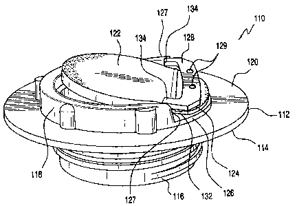
FIGURE 5 is a side perspective view of a new and
improved inflation valve assembly, constructed in accordance
with the principles and teachings of the present invention,
showing the various operative components thereof, and in par-
ticular, having a flapper valve member mounted upon the in-
flation valve assembly wherein the flapper valve member is
illustrated as being disposed at its CLOSED and SEATED posi-
tion;
FIGURE 6 is a side perspective view, similar to
that of FIGURE 5, of the new and improved inflation valve
assembly of the present invention as illustrated in FIGURE 5
showing, however, the flapper valve member disposed at its
OPENED and UNSEATED position; and
FIGURE 7 is an end perspective view, corresponding
with FIGURES 5 and 6, of the new and improved inflation valve
assembly of the present invention as illustrated within FIG-
URES 5 and 6, and likewise showing the flapper valve member
disposed at its OPENED and UNSEATED position as illustrated
within FIGURE 6.
DETAILED DESCRIPTION OF THE PREFERRED EMBODIMENT
Referring now to the drawings, and more particu-
larly to FIGURES 5-7 thereof, a new and improved inflation
valve assembly, constructed in accordance with the principles
and teachings of the present invention, is disclosed and is
generally indicated by the reference character 110. In con-
16
CA 02472845 2004-07-02
nection with the new and improved inflation valve assembly
110, it is initially noted that the new and improved infla-
tion valve assembly 110 of the present invention, as illus-
trated within FIGURES 5-7, is seen to be somewhat structural-
ly similar to the second, conventional, PRIOR ART inflation
valve assembly 10 as illustrated within FIGURE 2-4, and ac-
cordingly, those various operative component parts of the new
and improved inflation valve assembly 110 of the present in-
vention, as illustrated within FIGURES 5-7, which are similar
to those various operative component parts of the second,
conventional, PRIOR ART inflation valve assembly 10, as il-
lustrated within FIGURE 2-4, will be designated by reference
characters which are similar to those utilized to designate
the various operative component parts of the second, conven-
tional, PRIOR ART inflation valve assembly 10, except that
the reference characters for designating the various opera-
tive component parts of the new and improved inflation valve
assembly 110 of the present invention will be within the 100
series.
More particularly, the new and improved inflation
valve assembly 110, constructed in accordance with the prin-
ciples and teachings of the present invention, is seen to
comprise an annular flange member 112 wherein, for example,
the undersurface portion 114 of the annular flange member 112
is adapted to be heat-sealed, such as, for example, by means
of ultrasonic welding techniques, to an interior surface por-
tion of one of the plies comprising an inflatable bladder,
wherein the inflatable bladder may be similar to the inflat-
able bladder 62 as disclosed within the aforenoted patent to
Krier et al. An externally threaded nipple portion 116 of the
17
CA 02472845 2004-07-02
inflation valve assembly 110 is integrally formed upon the
undersurface portion 114 of the annular flange member 112 so
as to extend downwardly therefrom, and in this manner, the
threaded nipple portion 116 is adapted to project outwardly
through a suitable aperture formed within the ply of the in-
flatable bladder to which the undersurface portion 114 of the
annular flange member 112 is secured, as well as through
suitable apertures formed within the one or more paper plies
comprising the dunnage or cargo air bag. Accordingly, when a
suitable inflation nozzle, not shown, is fluidically connect-
ed to the nipple portion 116 of the inflation valve assembly
110, pressurized air or compressed air can be conducted into
the interior of the inflatable bladder so as to inflate the
same. In addition to the aforenoted structure characteristic
of the new and improved inflation valve assembly 110, it is
further seen that the new and improved inflation valve assem-
bly 110 also has a substantially annular upstanding ring mem-
ber 118 which is integrally formed upon the upper surface
portion 120 of the annular flange member 112 so as to extend
upwardly therefrom, and in this manner, the upstanding ring
member 118 is adapted to project inwardly into the inflatable
bladder of the dunnage or cargo air bag so as to in fact be
disposed internally within the inflatable bladder of the dun-
nage or cargo air bag.
Continuing further, and as can best be appreciated
from FIGURE 7, a substantially planar, disc-type flapper
valve member 122, having a substantially circular configura-
tion, has an end portion 124 which is adapted to be fixedly
secured upon the inflation valve assembly 110, however, con-
trary to the second conventional PRIOR ART inflation valve
18
CA 02472845 2004-07-02
assembly 10 as disclosed within FIGURES 2-4, the end portion
124 of the substantially planar, disc-type flapper valve mem-
ber 122 is secured directly to an arcuate section 126 of the
upper surface portion 120 of the annular flange member 112 by
means of a fixation bar 128 which extends along a chordal ex-
tent of the upper surface portion 120 of the annular flange
member 112. In particular, it is seen, as may best be appre-
ciated from FIGURES 5-7, that the substantially annular up-
standing ring member 118 actually has a substantially C-shap-
ed configuration, whereby the substantially C-shaped upstand-
ing ring member 118 defines terminal end portions 127,127
which are circumferentially spaced from each other so as to
spatially accommodate the end portion 124 of the flapper
valve member 122, as well as the fixation bar 128, therebe-
tween. Accordingly, in view of the fact that the end portion
124 of the substantially planar, disc-type flapper valve mem-
ber 122 is in fact secured directly to the arcuate section
126 of the upper surface portion 120 of the annular flange
member 112, as opposed to being secured to an arcuate section
of the annular upstanding ring member 118, such a structural
interrelationship comprises a first factor by means of which
the thickness dimension or depth profile of the entire infla-
tion valve assembly 110 can be reduced as compared to, for
example, the thickness dimension or depth profile of the sec-
ond conventional PRIOR ART inflation valve assembly 10.
It is noted further that in connection with the
mounting of the fixation bar 128 upon the arcuate section 126
of the upper surface portion 120 of the annular flange member
112, a pair of laterally separated, upstanding studs or riv-
ets 129,129 may be integrally formed upon the arcuate section
19
CA 02472845 2004-07-02
126 of the upper surface portion 120 of the annular flange
member 112. The studs or rivets 129,129 are adapted to extend
upwardly through suitable apertures formed within the fixa-
tion bar 128, whereupon the terminal end portions of the
studs or rivets 129,129 being heat sealed or otherwise termi-
nated, the fixation bar 128 is fixedly secured upon the arcu-
ate section 126 of the upper surface portion 120 of the annu-
lar flange member 112. Still further, and as can best be seen
from FIGURE 6, the radially interior peripheral wall portion
of the substantially C-shaped upstanding ring member 118 is
provided with an inner flange member 130 which is effectively
adapted to serve as a valve seat for the substantially plan-
ar, disc-type flapper valve member 122 when the flapper valve
member 122 is disposed at its CLOSED position or state as
substantially illustrated within FIGURE 5, and the inner
flange member 130 is also seen to be disposed upon the upper
end portion of the inner peripheral wall member 131 of the
externally threaded nipple portion 116. The inner peripheral
wall member 131 effectively defines a through-bore 133 which
is fluidically connected to the free or distal end portion of
the externally threaded nipple portion 116 whereupon the in-
flation nozzle, not shown, beiong fluidically connected to
the nipple portion 116 of the inflation valve assembly 110,
pressurized air or compressed air can be conducted into the
interior of the inflatable bladder, through means of the
through-bore 133, so as to inflate the same.
It is also noted that the substantially planar,
disc-type flapper valve member 122 is fabricated from a suit-
able rubber composition, and accordingly, that portion of the
substantially planar, disc-type flapper valve member 122,
CA 02472845 2004-07-02
which is disposed immediately adjacent to the fixation bar
128, inherently defines a living hinge portion 132 by means
of which the flapper valve member 122 is adapted to be read-
ily pivotally moved between its OPENED and CLOSED positions
as respectively disclosed within FIGURES 6 and 7, and FIGURE
5. As can be additionally appreciated from FIGURES 5-7, the
opposite ends of the fixation bar 128 are respectively pro-
vided with oppositely disposed, inwardly oriented detent mem-
bers 134, and it can therefore be appreciated that when the
substantially planar, disc-type flapper valve member 122 is
moved from its CLOSED position as substantially illustrated
in FIGURE 5, to its fully OPENED position as illustrated in
FIGURES 6 and 7, the opposite side portions of the flapper
valve member 122 will encounter the oppositely disposed, in-
wardly oriented detent members 134,134 of the fixation bar
128. In this manner, the opposite side portions of the flap-
per valve member 122 will accordingly be partially deformed
as a result of being compressed radially inwardly by means of
such detent members 134,134 whereupon the flapper valve mem-
ber 122 will therefore effectively be able to be moved past
such detent members 134,134.
Subsequently, once the side portions of the flapper
valve member 122 have in fact moved past such detent members
134,134, the side portions of the flapper valve member 122
will effectively regain their normal, non-compressed states
such that the detent members 134,134 will now serve to retain
the flapper valve member 122 at its OPENED position or state
as illustrated within FIGUERS 6 and 7. It is noted that in
order to manually manipulate the flapper valve member 122 and
to move the same from its CLOSED position as substantially
21
CA 02472845 2004-07-02
illustrated within FIGURE 5, to its fully OPENED position as
illustrated within FIGURES 6 and 7, the external or undersur-
face portion of the flapper valve member 122 is preferably
provided with an outwardly or downwardly extending projection
or finger member or block, similar to the aforenoted outward-
ly or downwardly extending projection or finger block or mem-
ber 36 utilized in conjunction with the flapper valve member
22 of the inflation valve assembly 10, although such a finger
member or block, for use upon the flapper valve member 122,
is not visible within FIGURES 5-7. It is noted further that
once the flapper valve member 122 is retained at its OPENED
position or state by means of the detent members 134,134, the
inflation valve assembly 110 is then able to have an infla-
tion nozzle member, not shown, fluidically mated with the
nipple portion 116 of the inflation valve assembly 110 so as
to facilitate inflation of the inflatable bladder of the dun-
nage or cargo air bag.
Accordingly, once the inflatable bladder of the
dunnage or cargo air bag has in fact been inflated to its de-
sirable extent, the inflation nozzle member, not shown, is
withdrawn from its fluidic connection with the nipple portion
116 of the inflation valve assembly 110, and as a result of
the relatively high internal pressurization of the inflatable
bladder of the dunnage or cargo air bag, the air pressure
disposed internally within the inflatable bladder of the dun-
nage or cargo air bag will force the flapper valve member 122
from its OPENED state or position, as illustrated within FIG-
URES 6 and 7, toward its CLOSED position or state as substan-
tially illustrated within FIGURE 5. More particularly, it can
be appreciated that the relatively high internal air pressure
22
CA 02472845 2004-07-02
disposed within the inflatable bladder of the dunnage or car-
go air bag will be sufficient enough to move the flapper
valve member 122 from its OPENED state or position, as illus-
trated within FIGURES 6 and 7, toward its CLOSED position or
state as substantially illustrated within FIGURE 5, as a re-
sult of causing the side portions of the flapper valve member
122 to effectively undergo deformation with respect to the
oppositely disposed detent members 134,134 of the fixation
bar 128, and thereby overcome the retention force of the de-
tent members 134,134 with respect to the side portions of the
flapper valve member 122, whereby the opposite side portions
of the flapper valve member 122 can move past the oppositely
disposed detent members 134,134 of the fixation bar 128. In
this manner, the movement of the flapper valve member 122 to
its CLOSED position or state, as substantially illustrated
within FIGURE 5, whereby the flapper valve member 122 is ef-
fectively disposed upon its valve seat 130, will prevent the
undesirable discharge of the pressurized air from the interi-
or of the inflatable bladder of the dunnage or cargo air bag
such that the dunnage or cargo air bag does not experience
undesirable deflation. Subsequently, a suitable threaded cap,
not shown, can be threadedly engaged upon the threaded nipple
portion 116 of the inflation valve assembly 110 so as to
permanently retain the pressurized air within the inflatable
bladder of the dunnage or cargo air bag, and thereby maintain
the dunnage or cargo air bag in its inflated state, until de-
flation of the dunnage or cargo air bag is in fact desired.
In light of the foregoing, it is to be specifically
noted and emphasized further that in view of the fact that
the opposite ends of the fixation bar 128 are provided with
23
CA 02472845 2004-07-02
the detent members 134,134 for encountering and operatively
engaging the side portions of the flapper valve member 122 so
as to releasably maintain the flapper valve member 122 at its
OPENED position or state, as opposed to the provision of the
upstanding projections or ears 34,34 upon the annular ring
member 18 of the first conventional PRIOR ART inflation valve
assembly 10, such a structural interrelationship comprises a
second factor by means of which the thickness dimension or
depth profile of the entire inflation valve assembly 110 can
be reduced as compared to, for example, the thickness dimen-
sion or depth profile of the second conventional PRIOR ART
inflation valve assembly 10. Accordingly, it is to be noted
further that this second factor, comprising the location of
the detent members 134,134 upon the opposite ends of the
fixation bar 128, and by means of which the thickness dimen-
sion or depth profile of the entire inflation valve assembly
110 can be reduced as compared to, for example, the thickness
dimension or depth profile of the second conventional PRIOR
ART inflation valve assembly 10, operatively cooperates with
the aforenoted first factor, comprising the mounting of the
fixation bar 128 directly upon the upper surface portion 120
of the annular flange member 112, so as to contribute further
to the effective reduction in the depth profile or thickness
dimension of the entire inflation valve assembly 110 as com-
pared to, for example, the thickness dimension or depth pro-
file of the second conventional PRIOR ART inflation valve as-
sembly 10.
Thus, it may be seen that in accordance with the
principles and teachings of the present invention, there has
been provided a new and improved inflation valve assembly
24
CA 02472845 2004-07-02
wherein the relatively simple structure, comprising a rela-
tively small number of cooperating parts, of the conventional
PRIOR ART inflation valve assembly has been retained, how-
ever, contrary to the structural features of such convention-
al PRIOR ART inflation valve assembly, the substantially
large height dimension or depth profile, characteristic of
the conventional PRIOR ART inflation valve assembly, has ef-
fectively been able to be reduced such that the new and im-
proved inflation valve assembly can be structurally incorpo-
rated within the inflatable bladder member of the dunnage or
cargo air bag at, for example, the operationally desirable
corner position of the inflatable bladder member so as to in
fact be capable of readily facilitating the inflation of the
dunnage or cargo air bag when the dunnage or cargo air bag is
to be utilized for securing or bracing cargo within the cargo
holds of, for example, railroad cars, airplanes, ships, truck
trailers, and the like.
Obviously, many variations and modifications of the
present invention are possible in light of the above teach-
ings. For example, while the inflation valve has been dis-
closed as being used in conjunction with an inflatable blad-
der adapted to be disposed internally within an outer bag
fabricated from a plurality of paper plies, the inflatable
bladder may alternatively be disposed within an outer bag
which may be fabricated from materials other than paper, or
alternatively still further, the inflatable bladder may it-
self comprise the dunnage bag, that is, it need not be dis-
posed or enclosed within an outer bag. In addition, the in-
flatable bladder may be fabricated from various different ma-
terials, such as, for example, VALERON , polyethylene with
CA 02472845 2004-07-02
woven NYLON , a single-ply KRAFT" paper laminated with poly-
ethylene, and the like. Still further, while the flange por-
tion of the inflation valve assembly has been noted as being
fixedly mounted upon, or heat-sealed to, an interior surface
portion of the inflatable bladder, it can likewise be mounted
upon, or heat-sealed to, an exterior surface portion of the
inflatable bladder. It is therefore to be understood that
within the scope of the appended claims, the present inven-
tion may be practiced otherwise than as specifically describ-
ed herein.
20
30
26