Note : Les descriptions sont présentées dans la langue officielle dans laquelle elles ont été soumises.
CA 02477066 2004-08-11
MASS SPECTROMETER
The present invention relates to a method of
determining the arrival time of one or more ions at an
ion detector, a mass spectrometer and a method of mass
spectrometry.
In a Time of Flight mass spectrometer bunches of
ions are caused to enter a field free flight region with
essentially the same kinetic energy. Ions with
different mass to charge ratios will therefore travel
with different velocities through the flight region and
will reach a detector arranged at the end of the flight
region at different times. The mass to charge ratios of
the ions can then be determined by determining the
transit times of the ions through the flight region.
Microchannel Plate ("MCP") detectors, discrete
dynode electron multipliers or combinations of these
devices are most commonly used as ion detectors in Time
of Flight mass spectrometers. These detectors produce a
bunch of electrons in response to an ion arriving at the
ion detector. The electrons produced by the ion
detector in response to an ion arrival are collected on
one or more collection electrodes or anodes which are
connected to a charge sensing discriminator. The signal
produced by the charge sensing discriminator in response
to electrons striking the collection electrode is
commonly recorded using a multi stop Time to Digital
Converter ("TDC") recorder. The clock of the TDC
recorder is started as soon as a bunch of ions first
enters the flight region of the Time of Flight mass
spectrometer. Events recorded in response to the charge
sensing discriminator output record the transit time of
the ions through the flight region. A known 10 GHz TDC
CA 02477066 2004-08-11
- 2 -
is able to record the arrival time of an ion at the ion
detector to within 100 Ps.
In order to produce a complete mass spectrum,
bunches of ions are repeatedly pulsed into the flight
region. The transit times of all the ions through the
flight region as recorded by the TDC recorder are used
to produce a histogram of the number of ion arrivals as
a function of the mass to charge ratio of the ions.
In a typical ion detector comprising a pair of
microchannel plate detectors a bunch of electrons
released from the microchannel plate detectors and
incident upon a collection electrode arranged to receive
the electrons will produce a signal input to a
discriminator having an approximately Gaussian shape.
Commonly such single ion peaks normally have a FWHM of
between 0.5 and 3 ns. The average area of the ion peak
will depend upon the gain of the ion detector. As will
be appreciated by those skilled in the art, there will
be a distribution of ion peak areas and thus ion peak
intersites associated with the detection of ions using a
microchannel plate detector even though the ions may
have identical mass to charge ratios and velocities.
This distribution arises due to the statistical nature
of electron multiplication in the microchannel plate or
other form of detector and the saturation
characteristics of the multiplier. For a pair of
microchannel plate detectors operated at a gain of
approximately 10 thisPulse Height Distribution ("PHD")
is itself approximately Gaussian. The Pulse Height
Distribution of a microchannel plate is generally
described as the mean height of the signal as a
percentage of the FWHM of the distribution of ion
CA 02477066 2004-08-11
- 3 -
heights recorded. For this particular detector
configuration a Pulse Height Distribution of 100-150%
FWHM is common. If microchannel plate detectors are
operated at low gain or discrete dynode electron
multipliers or photo multipliers are used, then the
Pulse Height Distribution has a different characteristic
namely a negative exponential distribution. In any
event it is apparent that there is a significant spread
in ion signal intensities for single ion arrivals which
must be somehow accommodated by the discriminator
electronics.
Two main types of discriminators are commonly used
in mass spectrometers. The simplest type of
discriminator is a leading edge detector. The arrival
time of an ion is recorded when the leading edge of an
ion signal passes through or exceeds a predetermined
intensity threshold. A count of 1 is then added to an
histogram of intensity against flight time at the
particular flight time associated with the ion signal
crossing the intensity threshold. Digital electronics
within the architecture of a multi stop Time to Digital
Converter recorder are arranged to respond when the
signal from the collection electrode (after
amplification) exceeds that of the pre-set intensity
threshold.
The other main type of discriminator is a Constant
Fraction Discriminator ("CFD") or zero crossing (i.e.
peak top) discriminator. The arrival time of an ion is
recorded when the ion signal exceeds or reaches a
predetermined percentage of the maximum height of the
ion signal. In the particular case of a peak top
discriminator this fraction is 100% of the maximum
CA 02477066 2004-08-11
- 4 -
height of the ion signal. Zero crossing refers to the
point at which the first differential of the ion signal
crosses zero.
There are two main drawbacks to using digital
leading edge detection discriminators. A first problem
is that the Pulse Height Distribution associated with an
ion detector leads to a time spread or jitter in the
time recorded for ion arrivals. For example, a first
ion arriving at the ion detector at a time Ti will
produce an ion signal having a maximum height Hl. Such
an ion signal will pass through a pre-set intensity
threshold at a time Ti' and an event will be recorded in
the closest corresponding time bin of the TOO. However,
a second ion arriving at the ion detector at an
identical time Ti may produce an ion signal which has a
maximum height H2 which is greater than Hl.
Accordingly, such an ion signal will pass through the
pre-set intensity threshold at a slightly earlier time
Tl". The event as recorded by the TOO will therefore
be recorded in an earlier time bin of the TOO to that of
the first ion. The magnitude of this time jitter is
related to the gradient of the leading edge of the ion
signal and the Pulse Height Distribution of the
detector. This effect leads to a decrease in the mass
resolution of the final histogram and hence of the mass
analyser.
A second problem with using a leading edge
detection discriminator is that the ion signal must also
drop below the same pre-set intensity threshold before
another ion can be detected i.e. before the leading edge
of a second ion signal due to another ion arriving at
the ion detector can be recorded. For single ion peak
CA 02477066 2004-08-11
- 5 -
widths of 2.5 ns FWHM this can lead to a dead-time of up
to 5 ns. This dead-time refers to the time after which
an ion has arrived at the ion detector and is being
recorded and during which time no further ion arrivals
can be recorded.
Multi stop TDCs should ideally be operated such
that the input signal remains above the pre-set
intensity threshold for approximately two time bins for
an event to be recorded. In addition, the signal should
remain below the pre-set intensity threshold for two
time bins before a second ion arrival event can be
recorded. This requirement leads to an inherent dead-
time associated with TDCs related to the speed of
digitisation. The dead-time associated with a single
ion peak width is generally larger that the inherent
dead-time of a TDC itself when clock rates > 1 GHz are
used.
If two ions have identical mass to charge ratios
and arrive at an ion detector from the same bunch of
ions pulsed into the time of flight region and arrive at
the ion detector during one dead-time period, then the
arrival of the second ion will not be recorded. If the
analyte signal is particularly intense then the number
of ions having the same mass to charge ratio in the same
ion bunch pulsed into the time of flight region may be
correspondingly large with the result that a significant
proportion of ions arriving at the ion detector will not
be detected. The mass to charge ratio value measured in
the final mass histogram will therefore be shifted to
lower mass to charge ratio and the total number of ions
recorded will be less than the true number of ions
arriving at the ion detector. Furthermore, when more
CA 02477066 2004-08-11
- 6 -
than one ion arrives at the ion detector separated in
time by less than the FWHM of a single ion pulse, then
the resulting ion signals will combine to produce an ion
signal input to the discriminator which is generally
larger than that for a single ion arrival. Using a
fixed pre-set intensity threshold to determine ion
arrival time will therefore lead to an additional
systematic shift to lower recorded mass to charge ratio.
It is possible to address some of these problems
using a Constant Fraction Discriminator set to record an
ion arrival when the ion signal exceeds a certain
percentage of the maximum peak height. This enables the
jitter associated with the Pulse Height Distribution of
the ion detector to be minimised. Similarly, the
systematic shift to low mass to charge ratio associated
with the heights of multiple ion arrivals will also be
minimised.
Using a peak top discriminator (which is
essentially a Constant Fraction Discriminator set to
record an ion arrival when the ion signal is at 100% of
the maximum height) enables the arrival time jitter and
mass to charge ratio shift related to single or multiple
ion peak heights also to be minimised. In addition, an
improved measurement of the mean ion arrival time for
overlapping multiple ion arrivals can be obtained. If
two ions arrive at the ion detector from the same bunch
of ions and produce ion signals having identical heights
and areas, then if the individual ion signals are
separated in time by less than the FWHM of a single ion
peak, then the two ion signals will combine to produce a
resultant ion signal having twice the area of an
individual ion signal. Although a peak top
CA 02477066 2004-08-11
- 7 -
discriminator should in theory determine the mean
arrival time of the two ions, in reality because the
heights and thus areas of the two ion signals are
unlikely to be exactly identical, then the peak top
measurement for multiple ion arrivals will be subject to
some statistical variation. This variation will though
tend to be averaged in the final histogram. However,
although Constant Fraction Discriminators and peak top
discriminators have certain advantages compared to
leading edge detectors, they also suffer from dead-time
problems. In general there is a period of about 5-10 ns
after an ion arrival is recorded during which no further
ions arrivals can be recorded. In the case of a
Constant Fraction Discriminator this leads to a
systematic shift in the mass to charge ratio recorded in
the final histogram. This shift will though not be
quite as pronounced as the equivalent situation using a
fixed pre-set intensity threshold leading edge detection
discriminator.
In the case of a peak top discriminator, a
systematic shift to low mass to charge ratio is only
evident when the spread of ion arrivals in the final
histogrammed peak (equivalent to the mass resolution of
the instrument) exceeds a certain value. For
illustration, if two ions arrive from the same ion bunch
separated in time by more than the FWHM of a single ion
peak, then the resultant ion signal will have two local
maxima. Using a peak top discriminator only the first
maxima will be recorded if the second maxima falls
within the dead-time of the first (which is often the
case). This again leads to a systematic shift to lower
mass to charge ratio in the final histogram.
CA 02477066 2004-08-11
- 8 -
In all cases only one event may be recorded during
one dead-time period. When significant numbers of ions
arrive at substantially the same time the number of ion
arrivals recorded in the final histogram will be less
than the total number of ions actually arriving at the
ion detector.
For these types of ion counting systems it is known
to attempt to correct the mass to charge ratios and ion
signal intensities reported in the final mass histogram
using a method of dead-time correction. Dead-time
correction may, for example, be applied to the ion count
in each time bin of the final mass histogram or
dead-time correction may be applied to individual mass
spectral peaks based upon a predetermined look-up table.
Further discussion of dead-time correction techniques is
given in WO 98/21742 (US-6373052) Hoyes, et al. The
latter method allows real time correction of mass
spectra and allows data from detailed Monte-Carlo
modelling of the characteristics of individual
discriminators and detector Pulse Height Distributions
and output peak widths and shapes to be accommodated.
Dead-time correction, however, cannot accurately be
applied when the ion signal intensity is changing
dynamically during the time taken to accumulate complete
mass spectra. If the ion intensity is changing in a
known way this can be incorporated to some extent into
the dead-time model. However, in reality, the ion
intensity tends to change in an unpredictable manner and
hence the average amount of correction to be applied can
only be approximated by examining the rate of change
from mass spectra to mass spectra as the experiment
proceeds. For example, as analyte elutes from a
CA 02477066 2004-08-11
- 9 -
chromatographic inlet its intensity will be changing
during the time frame of a single histogram. Similarly,
for systems using RF multipole rod set ion guides as
ion-transfer devices, the transmission characteristics
of the ion guide may vary during the time necessary to
accumulate a histogram. This allows a broad cross
section of ions having different mass to charge ratio
values to be transmitted. The intensity of individual
mass to charge ratio values within this histogram period
will be changing at different rates during this
procedure. Complex models are required in order to
attempt to accommodate these changes to allow the amount
of dead-time correction to be approximated. This can
lead both to mass and intensity errors. The accuracy
and precision required for dead time correction of mass
to charge ratio value is often in the order of 1-5
ppm. However, for quantitative work the accuracy and
precision for intensity correction is generally of the
order of 5-10%. It can be seen therefore that
relatively crude approximate models for dead time
correction may suffice for intensity correction but lead
to unacceptable errors in mass measurement.
It is therefore desired to provide an improved ion
detection system and method of determining the ion
arrival time at an ion detector.
According to an aspect of the present invention
there is provided an ion detector for a mass
spectrometer comprising:
a detector which generates, in use, a signal in
response to one or more ions arriving at the detector;
CA 02477066 2004-08-11
- 10 -
means for determining a first time when a leading,
rising, first or initial edge of the signal crosses or
exceeds a first threshold or level;
means for determining a second time when a
trailing, falling, second or subsequent edge of the
signal crosses or falls below a second threshold or
level; and
means for combining or averaging the first and
second times to provide an ion arrival time.
According to the preferred embodiment the signal in
response to one or more ions arriving at the ion
detector initially increases from a baseline value (i.e.
zero), peaks and then decreases back to the baseline
value. However, according to another embodiment the
signal may be inverted i.e. the signal initially
decreases from a baseline value, reaches a trough and
then increases back to the baseline value. Both
embodiments are intended to fall within the scope of the
independent claims.
The detector preferably comprises a channel
electron multiplier such as one or more microchannel
plates. According to the preferred embodiment at least
two microchannel plates are arranged to form at least
one chevron pair of microchannel plates. Ions are
received at an input surface of the one or more
microchannel plates and electrons are released from an
output surface of the one or more microchannel plates.
The detector preferably further comprises one or more
collection electrodes or anodes arranged to receive in
use at least some of the electrons released from the one
or more microchannel plates.
CA 02477066 2004-08-11
- 11 -
According to another embodiment the detector may
comprise one or more discrete dynode electron
multipliers, or a scintillator or phosphorous screen
(preferably in combination with a photo-multiplier).
The first threshold or level and/or the second
threshold or level preferably comprise an intensity
threshold or level. According to the preferred
embodiment the first threshold or level is substantially
the same as the second threshold or level. However,
according to a less preferred embodiment the first
threshold or level may be substantially different to
(i.e. greater or smaller than) the second threshold or
level.
The ion detector preferably comprises means for
associating a leading, rising, first or initial edge of
the signal with the closest detected trailing, falling,
second or subsequent edge.
If the ion signal comprises multiple leading,
rising, first or initial edges and/or multiple trailing,
falling, second or subsequent edges then a leading,
rising, first or initial edge is associated with the
trailing, falling, second or subsequent edge which is
closest in time to the particular leading, rising, first
or initial edge.
The ion detector preferably comprises a first Time
to Digital Converter for determining the first time
and/or the second time. Optionally, a second Time to
Digital Converter may be provided for determining the
first time and/or the second time. The first Time to
Digital Converter and/or the second Time to Digital
Converter may be arranged to use leading edge
discrimination to determine the first time and/or the
CA 02477066 2004-08-11
- 12 -
second time. Alternatively, the first Time to Digital
Converter and/or the second Time to Digital Converter
may be arranged to use constant fraction discrimination
to determine the first time and/or the second time.
According to a less preferred embodiment the ion
detector may comprise a first Analogue to Digital
Converter for determining the first time and/or the
second time. Optionally, a second Analogue to Digital
Converter may be provided for determining the first time
and/or the second time.
According to an aspect of the present invention
there is provided a mass spectrometer comprising an ion
detector as described above.
The mass spectrometer preferably comprises a Time
of Flight mass spectrometer, but according to less
preferred embodiments the mass spectrometer may comprise
a quadrupole mass analyser, a Penning mass analyser, a
Fourier Transform Ion Cyclotron Resonance ("FTICR") mass
analyser, a 2D or linear quadrupole ion trap, a Paul or
3D quadrupole ion trap or a magnetic sector mass
analyser.
The mass spectrometer preferably further comprises
an ion source selected from the group consisting of: (i)
an Electrospray Ionisation ("ESI") ion source; (ii) an
Atmospheric Pressure Ionisation ("API") ion source;
(iii) an Atmospheric Pressure Chemical Ionisation
("APCI") ion source; (iv) an Atmospheric Pressure Photo
Ionisation ("APPI") ion source; (v) a Laser Desorption
Ionisation ("LDI") ion source; (vi) an Inductively
Coupled Plasma ("ICP") ion source; (vii) a Fast Atom
Bombardment ("FAB") ion source; (viii) a Liquid
Secondary Ion Mass Spectrometry ("LSIMS") ion source;
______
CA 02477066 2004-08-11
- 13 -
(ix) a Field Ionisation ("Fl") ion source; (x) a Field
Desorption ("FD") ion source; (xi) an Electron Impact
("El") ion source; (xii) a Chemical Ionisation ("CI")
ion source; (xiii) a Matrix Assisted Laser Desorption
Ionisation ("MALDI") ion source; and (xiv) a Desorption
Ionisation on Silicon ("DIOS") ion source.
The ion source may be either continuous or pulsed.
According to another aspect of the present
invention there is provided an ion detector for a mass
spectrometer comprising:
a detector which generates, in use, a signal in
response to one or more ions arriving at the detector;
means for determining a first time when a leading,
rising, first or initial edge of the signal crosses or
exceeds a first threshold or level;
means for determining a second time when a
trailing, falling, second or subsequent edge of the
signal crosses or falls below a second threshold or
level; and
means for averaging the signal intensity between
the first and second times to provide an ion arrival
time.
The means for averaging the signal intensity
between the first and second times preferably determines
a weighted average ion arrival time. Preferably, the
means for averaging the signal intensity between the
first and second times determines a weighted average ion
arrival time within time bins bounded by the first time
and the second time. Further preferably, the means for
averaging the signal intensity between the first and
second times determines the sum of all the intensities
CA 02477066 2004-08-11
- 14 -
of at least 50%, 60%, 70%, 80%, 90%, 95% or 100% of the
time bins bounded by the first time and the second time.
The ion detector may comprise a first Analogue to
Digital Converter for determining the first time and/or
the second time. Optionally, a second Analogue to
Digital Converter may be provided for determining the
first time and/or the second time.
According to another aspect of the present
invention there is provided a method of determining the
arrival time of one or more ions at a detector
comprising:
generating a signal in response to one or more ions
arriving at the detector;
determining a first time when a leading, rising,
first or initial edge of the signal crosses or exceeds a
first threshold or level;
determining a second time when a trailing, falling,
second or subsequent edge of the signal crosses or falls
below a second threshold or level; and
combining or averaging the first and second times
to provide an ion arrival time.
According to another aspect of the present
invention there is provided a method of determining the
arrival time of one or more ions at a detector
comprising:
generating a signal in response to one or more ions
arriving at the detector;
determining a first time when a leading, rising,
first or initial edge of the signal crosses or exceeds a
first threshold or level;
CA 02477066 2004-08-11
- 15 -
determining a second time when a trailing, falling,
second or subsequent edge of the signal crosses or falls
below a second threshold or level; and
averaging the signal intensity between the first
and second times to provide an ion arrival time.
The preferred embodiment relates to a method for
detecting ions arriving at an ion detector in single
Time of Flight mass spectra which minimises the effect
of dead-time on the mass to charge ratio measurement
accuracy. According to the preferred embodiment,
detection of single or multiple ion arrival times during
a single Time of Flight experiment is achieved by
recording the times at which both the leading and the
trailing (falling) edge of an ion signal produced by a
collection electrode crosses a predetermined
discriminator intensity threshold. Using the times
recorded for both the leading and the trailing edge of
the ion signal to calculate an average ion arrival time
allows a more accurate determination of the mean arrival
time especially when multiple ions arrive at the ion
detector at substantially the same time. The preferred
method of ion arrival detection and determination
results in a mass measurement accuracy of the final
histogrammed peak which is independent of dead-time
effects. With no dead-time correction required for mass
to charge ratio measurement at high count rates, error
due to dynamically changing signals within an individual
histogram is effectively removed.
Various embodiments of the present invention will
now be described, by way of example only, and with
reference to the accompanying drawings in which:
CA 02477066 2004-08-11
- 16 -
Fig. 1A illustrates using leading edge detection to
determine an ion arrival, Fig. 1B illustrates how using
leading edge detection results in a different recorded
arrival time for an ion having the same mean flight time
as in the example shown in Fig. lA but wherein the ion
detector produces a less intense ion signal in response
to an ion arrival, Fig. 1C illustrates using leading
edge detection to determine an average ion arrival time
when two ions arrive at similar times and Fig. 1D
illustrates using leading edge detection to determine an
average ion arrival time when two ions arrive at
slightly delayed times;
Fig. 2A illustrates using a constant fraction
discriminator to determine an ion arrival, Fig. 2B
illustrates how a constant fraction discriminator
correctly records the same flight time irrespective of
the intensity of the ion signal produced by the ion
detector in response to an ion arrival, Fig. 2C
illustrates using a constant fraction discriminator to
determine an average ion arrival time when two ions
arrive at similar times and Fig. 2D illustrates using a
constant fraction discriminator to determine an average
ion arrival time when two ions arrive at slightly
delayed times;
Fig. 3A illustrates using peak top detection to
determine an ion arrival, Fig. 3B illustrates how a peak
top detector correctly records the same flight time
irrespective of the intensity of the ion signal produced
by the ion detector in response to an ion arrival, Fig.
30 illustrates how a peak top detector correctly
determines an average ion arrival time when two ions
arrive at similar times and Fig. 3D illustrates how a
CA 02477066 2004-08-11
- 17 -
peak top detector fails to correctly determine an
average ion arrival time when two ions arrive at
slightly delayed times;
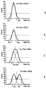
Fig. 4A illustrates a preferred method of
determining an ion arrival time wherein the times at
which the leading and trailing edges of an ion signal
cross an intensity threshold are detected and the times
averaged, Fig. 4B illustrates how the preferred method
of determining an ion arrival time records the same
flight time irrespective of the intensity of the ion
signal produced by the ion detector in response to an
ion arrival, Fig. 40 illustrates how the preferred
method of determining an ion arrival time correctly
determines an average ion arrival time when two ions
arrive at similar times and Fig. 4D illustrates how the
preferred method of determining an ion arrival time
correctly determines an average ion arrival time when
two ions arrive at slightly delayed times;
Fig. 5 illustrates the difference between an actual
measured ion signal and a theoretical ion signal for a
simulation wherein the ion detector system uses leading
edge detection to determine ion arrival times;
Fig. 6 illustrates the difference between an actual
measured ion signal and a theoretical ion signal for a
simulation wherein the ion detector system uses a
constant fraction discriminator to determine ion arrival
times;
Fig. 7 illustrates the difference between an actual
measured ion signal and a theoretical ion signal for a
simulation wherein the ion detector system uses a peak
top discriminator to determine ion arrival times; and
CA 02477066 2004-08-11
- 18 -
Fig. 8 illustrates the difference between an actual
measured ion signal and a theoretical ion signal for a
simulation wherein the ion detector system uses a method
of determining ion arrival times according to the
preferred embodiment of the present invention.
In order to understand the various differences
between conventional techniques of determining the
arrival time of an ion and the preferred method of
determining the arrival time of an ion, a number of
different conventional approaches will first be
described with reference to Figs. 1-3. Figs. 1A-1D
illustrate determining ion arrival time using simple
leading edge detection, Figs. 2A-2D illustrate
determining ion arrival time using leading edge
detection with a constant fraction discriminator and
Figs. 3A-3D illustrate determining ion arrival time
using peak top detection. These different approaches to
determining the ion arrival time will now be discussed
in more detail.
Fig. lA illustrates the ion signal recorded by a
collection electrode of an ion detector for a single ion
arriving at the ion detector and illustrates how the ion
arrival time may be determined using simple leading edge
detection. An ion arrival time T1 is recorded by a
leading edge discriminator which is set to detect and
record an ion arrival when the detected ion signal
intensity exceeds a pre-set intensity threshold. In the
particular example shown in Fig. lA the pre-set
intensity threshold is set at 50.
Fig. 1B illustrates the ion signal recorded by the
collection electrode of an ion detector for a single ion
arriving at the ion detector when the ion arrives at the
CA 02477066 2004-08-11
- 19 -
ion detector at the same time as the ion in the example
shown in Fig. 1A but wherein the resulting ion signal
produced by the ion detector has a lower intensity than
that of the ion signal shown in Fig. 1A. The lower
intensity ion signal may be due to the Pulse Height
Distribution of the ion detector. Although the mean
arrival time of the ion in the example illustrated by
Fig. 1B is identical to the example illustrated by Fig.
1A, it is apparent that when using leading edge
detection with a constant pre-set intensity threshold,
the recorded ion arrival time T2 when the ion signal is
less intense differs from the recorded ion arrival time
Ti when the ion signal is more intense.
The two different recorded ion arrival times T1,T2
as recorded using a leading edge discriminator result
from setting the discriminator to detect an ion arrival
when the ion signal intensity exceeds the same pre-set
intensity threshold. The difference in the two recorded
ion arrival times T1,T2 for two ions which have the same
mean arrival time illustrates the time jitter associated
with using a simple leading edge discriminator. The
time jitter is mainly due to the Pulse Height
Distribution of the ion detector.
Fig. 10 illustrates the resultant ion signal
recorded by a collection electrode of an ion detector
using simple leading edge detection when two ions arrive
at the ion detector at similar times and the individual
ion signals are separated in time by less than the FWHM
of a single ion signal. An ion arrival time T3 is
recorded by a leading edge discriminator set to detect
and record an ion arrival when the detected ion signal
intensity exceeds a pre-set intensity threshold. In the
......
CA 02477066 2004-08-11
- 20 -
particular example shown in Fig. 1C the pre-set
intensity threshold is set at 50. Whilst the mean
arrival time of the two ion signals has moved
appreciably to a higher flight time compared to the ion
arrival time shown in the examples in Figs. lA and 1B,
the ion arrival time T3 as actually recorded by the
leading edge discriminator does not reflect any such
shift. When the probability of multiple ion arrivals at
substantially similar times is significant, this effect
leads to a systematic shift to lower flight time in the
final histogrammed mass spectra.
Fig. 1D illustrates the resultant ion signal
recorded by a collection electrode of an ion detector
using simple leading edge detection when two ions arrive
at the ion detector at slightly different times and the
individual ion signals are separated in time by more
than the FWHM of a single ion signal. An ion arrival
time T4 is recorded by a leading edge discriminator set
to detect and record an ion arrival when the detected
ion signal intensity exceeds a pre-set intensity
threshold. In the particular example shown in Fig. 1D
the pre-set intensity threshold is set at 50. Whilst
the mean arrival time of the two ion signals has moved
even more appreciably to a higher flight time compared
to the ion arrival time shown in the examples in Figs.
1A, 1B and 10, the ion arrival time T4 as actually
recorded by the leading edge discriminator again does
not reflect any such shift. When the probability of
multiple ion arrivals at slightly different times is
significant, this effect leads to a systematic
significant shift to lower flight time in the final
histogrammed mass spectra.
CA 02477066 2004-08-11
- 21 -
Fig. 2A illustrates the ion signal recorded by a
collection electrode of an ion detector for a single ion
arriving at the ion detector and illustrates how the ion
arrival time may be determined using a constant fraction
discriminator. An ion arrival time Ti is recorded by a
constant fraction discriminator which is set to detect
and record an ion arrival when the detected ion signal
intensity exceeds an intensity threshold which is set,
in this particular example, at 50% of the maximum height
of the peak.
Fig. 2B illustrates the ion signal recorded by the
collection electrode of an ion detector for a single ion
arriving at the ion detector when the ion arrives at the
ion detector at the same time as the ion in the example
shown in Fig. 2A but wherein the resulting ion signal
produced by the ion detector has a lower intensity than
that of the ion signal shown in Fig. 2A. The lower
intensity ion signal may be due to the Pulse Height
Distribution of the ion detector. Ion arrival time T2
indicates the arrival time recorded by the constant
fraction discriminator which is set to detect and record
an ion arrival when the detected ion signal intensity
exceeds an intensity threshold which is set, in this
particular example, at 50% of the maximum height of the
peak. In this case it can be seen that the ion arrival
time T2 as recorded by the constant fraction
discriminator is identical to the ion arrival time Ti as
recorded by the constant fraction discriminator in the
example shown in Fig. 2A. This illustrates the ability
of a constant fraction discriminator to minimise arrival
time jitter associated with the Pulse Height
CA 02477066 2004-08-11
- 22 -
Distribution of the ion detector which is problematic
when using simple leading edge detection.
Fig. 20 illustrates the resultant ion signal
recorded by a collection electrode of an ion detector
using a constant fraction discriminator when two ions
arrive at the ion detector at similar times and the
individual ion signals are separated in time by less
than the FWHM of a single ion signal. An ion arrival
time T3 is recorded by using a constant fraction
discriminator set to detect an ion arrival when the
detected ion signal intensity exceeds an intensity
threshold which is set, in this particular example, at
50% of the maximum height of the peak. Whilst the mean
arrival time of the two ion signals has moved
appreciably to a higher flight time compared to the ion
arrival time shown in the examples in Figs. 2A and 2B,
the ion arrival time T3 as actually recorded by the
constant fraction discriminator does not fully reflect
the magnitude of this shift. When the probability of
multiple ion arrivals at substantially similar times is
significant, this effect leads to a systematic shift to
lower flight time in the final histogrammed mass
spectra.
Fig. 2D illustrates the resultant ion signal
recorded by a collection electrode of an ion detector
using a constant fraction discriminator when two ions
arrive at the ion detector at slightly different times
and the individual ion signals are separated in time by
more than the FWHM of a single ion signal. An ion
arrival time T4 is recorded by a constant fraction
discriminator set to detect and record an ion arrival
when the detected ion signal intensity exceeds an
CA 02477066 2004-08-11
- 23 -
intensity threshold which, in this particular example,
is set at 50% of the maximum height of the peak. Whilst
the mean arrival time of the two ion signals has moved
even more appreciably to a higher flight time compared
to the ion arrival time shown in the examples in Figs.
2A, 23 and 2C, the ion arrival time T4 as actually
recorded by the constant fraction discriminator does not
reflect any such shift. When the probability of
multiple ion arrivals at slightly different times is
significant, this effect leads to a systematic shift to
lower flight time in the final histogrammed mass
spectra.
Fig. 3A illustrates the ion signal recorded by a
collection electrode of an ion detector for a single ion
arriving at the ion detector and illustrates how the ion
arrival time may be determined using a peak top
discriminator. An ion arrival time Ti is recorded by a
peak top discriminator when the detected ion signal
intensity reaches the maximum height of the peak.
Fig. 3B illustrates the ion signal recorded by the
collection electrode of an ion detector for a single ion
arriving at the ion detector when the ion arrives at the
ion detector at the same time as the ion in the example
shown in Fig. 3A but wherein the resulting ion signal
produced by the ion detector has a lower intensity than
that of the ion signal shown in Fig. 3A. The lower
intensity ion signal may be due to the Pulse Height
Distribution of the ion detector. Ion arrival time T2
indicates the arrival time recorded by a peak top
discriminator when the detected ion signal intensity
reaches the maximum of the peak. In this case it can be
seen that the ion arrival time T2 as recorded by the
_
CA 02477066 2004-08-11
- 24 -
peak top discriminator is identical to the ion arrival
time Ti as recorded by the peak top discriminator in the
example shown in Fig. 3A. This illustrates the ability
of a peak top discriminator to minimise arrival time
jitter associated with the Pulse Height Distribution of
the ion detector which is problematic when using simple
leading edge detection.
Fig. 3C illustrates the resultant ion signal
recorded by a collection electrode of an ion detector
using a peak top discriminator when two ions arrive at
the ion detector at similar times and the individual ion
signals are separated in time by less than the FWHM of a
single ion signal. An ion arrival time T3 is recorded
using a peak top discriminator set to detect an ion
arrival when the detected ion signal intensity reaches
the maximum height of the peak. The mean arrival time
of the two ion signals has moved appreciably to higher
flight time and the peak top discriminator has correctly
recorded the shift in arrival time.
Fig. 3D illustrates the resultant ion signal
recorded by a collection electrode of an ion detector
using a peak top discriminator when two ions arrive at
the ion detector at slightly different times and the
individual ion signals are separated in time by more
than the FWHM of a single ion signal. An ion arrival
time T4 is recorded by a peak top discriminator set to
detect an ion arrival when the detected ion signal
intensity reaches the maximum height of the peak.
Whilst the mean arrival time of the two ion signals has
moved even more appreciably to higher flight time
compared to the ion arrival time shown in the examples
in Figs. 3A, 3B and 3C, the ion arrival time T4 as
CA 02477066 2004-08-11
- 25 -
actually recorded by the peak top discriminator does not
reflect any such shift. Only the time for the first
apex of the combined ion signal is recorded as the
second apex falls within the dead-time of the
discriminator. When the probability of multiple ion
arrivals within this dead-time is significant, this
effect leads to a systematic shift to lower flight time
in the final histogrammed mass spectra.
The preferred method of determining the arrival
time of one or more ions at an ion detector will now be
described. In particular, the preferred approach is to
detect when both the leading and trailing edges of an
ion signal cross an intensity threshold and then to
combine and preferably average these two times.
Fig. 4A illustrates the ion signal recorded by a
collection electrode of an ion detector for a single ion
arriving at the ion detector and illustrates how the ion
arrival time is recorded according to the preferred
method of ion detection. An ion arrival time Ti is
recorded according to the preferred embodiment by
determining the times Tla,T1b at which the leading and
trailing edges of the ion signal cross a predetermined
intensity threshold. The ion arrival time Ti as
recorded according to the preferred embodiment is
preferably the average or mean of these two times
Tla,T1b.
Fig. 4B illustrates the ion signal recorded by a
collection electrode of an ion detector for a single ion
arriving at the ion detector when the ion arrives at the
ion detector at the same time as the ion in the example
shown in Fig. 4A but wherein the resulting ion signal
produced by the ion detector has a lower intensity than
CA 02477066 2004-08-11
- 26 -
that of the ion signal shown in Fig. 4A. The lower
intensity ion signal may be due to the Pulse Height
Distribution of the ion detector. Ion arrival time T2
indicates the arrival time as recorded according to the
preferred embodiment by averaging the times T2a,T2b at
which the leading and trailing edges of the ion signal
cross a predetermined intensity threshold. In this case
it can be seen that the ion arrival time T2 as recorded
according to the preferred embodiment is identical to
the ion arrival time Tl as recorded in the example shown
in Fig. 4A. This illustrates the ability of the
preferred embodiment to minimise arrival time jitter
associated with the Pulsed Height Distribution of the
ion detector which is problematic when using simple
leading edge detection.
Fig. 40 illustrates the resultant ion signal
recorded by a collection electrode of an ion detector
using the preferred method of ion detection when two
ions arrive at the ion detector at similar times and the
individual ion signals are separated in time by less
than the FWHM of a single ion signal. An ion arrival
time T3 is recorded according to the preferred
embodiment by averaging the times T3a,T3b at which the
leading and trailing edges of the ion signal cross a
predetermined intensity threshold. The mean arrival
time of the combined ion signals has moved appreciably
to higher flight time and the preferred method of ion
detection has correctly recorded the shift in arrival
time.
Fig. 4D illustrates the resultant ion signal
recorded by a collection electrode of an ion detector
using the preferred method of ion detection when two
,
CA 02477066 2004-08-11
- 27 -
ions arrive at the ion detector at slightly different
times and the individual ions are separated in time by
more than the FWHM of a single ion signal. An ion
arrival time T4 is recorded according to the preferred
embodiment by averaging the times T4a,T4b at which the
leading and trailing edges of the ion signal cross a
predetermined intensity threshold. The mean arrival
time of the combined ion signals has moved appreciably
to a higher flight time and the preferred method of ion
detection has importantly correctly recorded the shift
in arrival time. The resultant histogrammed mass
spectra will therefore show no adverse shift in flight
time due to dead-time effects. The preferred method of
ion detection therefore represents an important advance
in the art and enables a significantly improved ion
detection system to be provided.
A Monte Carlo model representing the histogram
generated for a mass spectral peak having a mass to
charge ratio of 800 and a resolution of 5000 (FWHM)
corresponding to a peak width at half height of 200 ppm
was run in order to further illustrate the different
methods of determining an ion arrival time. The model
consisted of a signal generated from 10,000 bunches of
ions having a mean number of two ions per bunch.
Considering a Poisson distribution of ions within each
of the 10,000 bunches of ions, the number of single and
multiple ion arrivals was determined to be: 2707 single
ion arrivals, 2707 double ion arrivals, 1804 triple ion
arrivals, 902 quadruple ion arrivals, 361 quintuple ion
arrivals, 120 sextuple ion arrivals, 34 septuple ion
arrivals and 9 octuple ion arrivals. A total of 19976
ions were simulated and the total number of separate
CA 02477066 2004-08-11
,
- 28 -
single and multiple ion events recorded was 8644. The
difference between the number of events actually
recorded (8644) and the actual number of ions simulated
(19976) was due to dead-time effects as previously
described. Knowing the average number of ions per bunch
enabled the recorded intensity to be partially corrected
using known methods of dead-time correction.
For the purposes of the simulation each ion was
generated with a FWHM of 2 ns and a random Gaussian
distribution of heights equivalent to a Pulsed Height
Distribution of 150%. The arrival time of each ion was
also generated from a Gaussian distribution with a mean
arrival time of 33.1 ns and a FWHM of 3.31 ns.
Ion arrival detection using conventional simple
leading edge detection, leading edge detection using a
constant fraction discriminator, and peak top detection
were simulated. The preferred method of detection based
upon the detection and averaging of the times that the
leading and trailing edges of the ion signal crossed an
intensity threshold was also simulated.
Fig. 5 shows the results of the simulation using
simple leading edge detection with a fixed pre-set
intensity threshold. Data generated by the simulation
is shown as a histogram and the solid line shows the
expected (theoretical) peak envelope if no distortion
due to dead-time effects occurred. The height of the
undistorted peak envelope has been normalised to the
highest intensity in the histogram generated by the
simulation. The measured ppm shift in mass to charge
ratio for the experimental data away from the expected
measurement was determined to be -44.5 ppm. The
CA 02477066 2004-08-11
- 29 -
estimated standard deviation error for this measurement
was determined to be 0.85 ppm.
Fig. 6 shows the results of the simulation using a
constant fraction discriminator with an intensity
threshold set at 10% of the height of the combined
signal. Data generated by the simulation is shown as a
histogram and the solid line shows the expected
(theoretical) peak envelope if no distortion due to
dead-time effects occurred. The height of the
undistorted peak envelope has been normalised to the
highest intensity in the histogram generated by the
simulation. The measured ppm shift in mass to charge
ratio for the experimental data away from the expected
measurement was determined to be -33.2 ppm. The
estimated standard deviation error for this measurement
was determined to be 0.85 ppm.
Fig. 7 shows the results of the simulation using a
peak top discriminator. Data generated by the
simulation is shown as a histogram and the solid line
shows the expected (theoretical) peak envelope if no
distortion due to dead-time effects occurred. The
height of the undistorted peak envelope has been
normalised to the highest intensity in the histogram
generated by the simulation. The measured ppm shift in
mass to charge ratio for the experimental data away from
the expected measurement was determined to be -22.3 ppm.
The estimated standard deviation error for this
measurement was determined to be 0.85 ppm.
Fig. 8 shows the results of the simulation using
the preferred method of determining ion arrival. Data
generated by the simulation is shown as a histogram and
the solid line shows the expected (theoretical) peak
--
CA 02477066 2004-08-11
- 30 -
envelope if no distortion due to dead-time effects
occurred. The height of the undistorted peak envelope
has been normalised to the highest intensity in the
histogram generated by the simulation. The measured ppm
shift in mass to charge ratio for the experimental data
away from the expected measurement was determined to be
-0.68 ppm (i.e. negligible). The estimated standard
deviation error for this measurement was determined to
be 0.85 ppm.
In the preferred embodiment the digital electronics
within a multi stop TDC are preferably used to record
the times at which the leading and trailing edge of the
signal produced by a collection electrode (due to either
a single ion arrival or to multiple ion arrivals) passes
through a pre-set intensity threshold. The TDC may use
either leading edge or constant fraction discrimination
to record the times at which the leading and trailing
edges exceed a certain threshold. A single time of
flight spectra recorded by the TDC will consist of pairs
of leading and trailing edge times. A detected leading
edge is preferably associated with the nearest detected
trailing edge. The times recorded may be flagged to
indicate leading and trailing edge times.
The times recorded for the leading edge and for the
trailing edge of a single ion arrival event are then
preferably averaged and a count of 1 is preferably added
to a histogram corresponding to this average arrival
time. This procedure is preferably repeated for the
next time of flight spectra until a complete
histogrammed mass spectrum is produced.
In an embodiment the signal from an ion arrival may
be passed to two separate TDCs or to a second input of a
CA 02477066 2004-08-11
- 31 -
single TDC. The leading edge may be recorded using one
TDC and the trailing edge recorded using another TDC or
a second input of a single TDC. The two times may then
be averaged and a count of 1 added to the histogram
corresponding to this average time.
In an embodiment a first constant fraction
discriminator may be used to detect the leading edge and
a second constant fraction discriminator may be used to
detect the trailing edge. The output from the
discriminators may be recorded using one or more TDCs or
a multiple input TDC.
In an embodiment the digital electronics within a
TDC may be used to record a count of 1 in the histogram
for all the time bins in which the input signal is above
a pre-set threshold. For each ion arrival event a
series of entries will be made in the histogram
corresponding to the width of the arrival event above
the pre-set threshold. Peaks in the final histogram
comprised of a significant number of multiple ion
arrivals will appear to be wider than those peaks with
predominantly single ion arrivals. The error in mass to
charge ratio assignment for the resultant histogrammed
peaks will again be minimised.
In another less preferred embodiment this method
may be applied to an Analogue to Digital (ADC) recording
device. For an individual ion arrival event the point
at which the leading and trailing edge of the signal
crosses a predetermined threshold may be recorded using
an ADC. In this case a weighted average arrival time
within the time bins bounded by the leading and trailing
edges detected may be calculated. The sum of the
intensities of all the time bins bounded by the leading
CA 02477066 2004-08-11
- 32 -
and trailing edge may also be recorded. A histogram may
then be constructed consisting of events recorded at the
average arrival time calculated with heights
corresponding to the total intensity calculated for that
event. For example, for times -it f t -2 = = tn and associated
intensities i ¨1, ¨2 r = = in recorded above a pre-set
intensity threshold for a single arrival event, the
weight average T is given by:
(t/xii)
T = J=IiI
Although according to the preferred embodiment the
intensity threshold for the leading and trailing edges
preferably remains the same, according to a less
preferred embodiment it is contemplated that the
intensity threshold may vary, at least slightly,
depending upon whether a leading edge or a trailing edge
was being compared therewith.
According to the preferred embodiment the times for
the ion signal to cross the intensity threshold for the
leading and trailing edge are combined and then divided
by two to produce an average (mean) value. However,
according to less preferred embodiments the two
different times may be combined and/or averaged in other
ways. For example, one or both times may be weighted
and some other average apart from the precise mean may
be determined or approximated.
Although the present invention has been described
with reference to preferred embodiments, it will be
CA 02477066 2012-03-12
-33-
understood by those skilled in the art that various changes in
form and detail may be made. The scope of the claims should
not be limited by the preferred embodiments set forth in the
examples, but should be given the broadest interpretation
consistent with the description as a whole.