Note : Les descriptions sont présentées dans la langue officielle dans laquelle elles ont été soumises.
CA 02477942 2004-09-01
WO 03/076148 PCT/US03/06633
-1-
METHOD OF PRODUCING CORE
COMPONENT, AND PRODUCT THEREOF
BACKGROUND OF THE INVENTION
FIELD OF THE INVENTION
The invention relates generally to the production of man-made
composite structural and building products molded from a mat of cellulosic
fibers produced by the dry process and molded to include one or more interior
depressions. More particularly, the invention relates to the production of a
cellulosic core component molded to include one or more interior depressions
which can be utilized, for example, in an interior space or void formed by a
shell or framework of a building product, particularly as a core component
that
is adhered between opposed doorskins, said core component having one or
more interior depressions shaped to receive depressions molded into the
doorskins.
BRIEF DESCRIPTION OF RELATED TECHNOLOGY
The irivention is described herein is an improvement over the
method and articles described in this Assignee's U.S. Patent No. 5,887,402
('402). The'402 patent describes a method of manufacturing a core component
and then post-press machining or routing one or more interior depressions into
at least over major surface of the core component to accommodate interior
depressions in the adhered doorskins. In accordance with the present
invention,
core components are manufactured to include the required interior depressions
in the pressing operation to eliminate or substantially reduce any post-press
machining.
CA 02477942 2004-09-01
WO 03/076148 PCT/US03/06633
-2-
Man-made boards, such as fiberboard, can be embossed or
molded to have three-dimensional shapes and various design and structural
features found in natural wood. Types of useful man-man boards are referred
to by the following terms, for example: (a) fiberboards such as hardboard
(e.g., low-density hardboard), soft board, and medium-density fiberboard and
(b) chipboards such as particleboard, medium-density particleboard, and
oriented strandboard ("OSB"). Composites of these boards are also useful.
Such boards, particularly hardboard, have f6und widespread use in the
manufacture of doorskins, which can be glued together or laminated to form a
shell which supports or encloses a structure or a frame.
Commonly, doorskins (also referred to as door faces) are molded
from a planar cellulosic mat to include one or more interior depressions or
contours, such as one or more square or rectangular depressions which do not
extend to the outer edge or periphery of the doorskin product. Doorskins often
require inclined molded walls having a plurality of contours that include
varied
curved and planar surfaces. Where the depressions or contours are included on
a doorskin product, this can serve to replicate a more expensive natural wood
paneled door. For example, doors having two, three, four, five, and six panel
designs are commonly produced. The exterior or visible surfaces of the
fiberboard also can be embossed with a design that represents a wood grain
pattern found in a natural piece of wood.
The principal'processes for the manufacture of wood composites
such as doorskins and other structural or building products include (a) wet
felted/wet pressed or "wet" processes, (b) dry felted/dry pressed or "dry"
processes, and (C) wet felted/dry pressed or "wet-dry" processes. The core
components of the present invention are manufactured by the dry process.
CA 02477942 2004-09-01
WO 03/076148 PCT/US03/06633
-3-
In the dry process of the present invention, the cellulosic fibers
are generally conveyed in a gaseous stream or by mechanical means rather than
a liquid stream. For example, the cellulosic fibers may be first coated with a
thermosetting resin binder, such as a phenol-formaldehyde resin. The fibers
are
then randomly formed into a mat by air blowing the resin-coated fibers onto a
support member. The mat may optionally be subjected to pre-press drying.
The mat, typically having a moisture content of less than about thirty weight
percent and preferably less than about ten weight percent, is then pressed
under
heat and pressure to cure the thermosetting resin and to compress the mat into
an integral consolidated structure.
The fiber mats that are made by the dry process do. not have as
much fiber intertangling of fibrillated fibers as mats made by the wet or
wet/dry
processes since the dry process fibers are not slurried in water during water
drainage, which enhances fiber intermingling and entangling, and are coated
with resin prior to substantial fiber intermingling. As a result, dry process
mats
that are consolidated by heat and pressure are not as strong as wet or wet/dry
process consolidated mats and have been found to suffer from surface peeling
when relatively thick dry process core components, e. g. , one half inch
thickness
or more, are roll-coated with adhesive for adherence to opposed doorskins.
Fiber mats have been pressed into pre-selected decorative shapes,
typically at a thickness of about one-eighth of an inch, to include one or
more
panels or depressions and/or other contours in the formation of doorskins, as
described above. Two doorskin pieces are typically joined together with an
adhesive binder, which is placed at least at the contact points along the
2 5 periphery of the door assembly formed by the doorskins. Because the
doorskin
pieces are contoured to include one or more depressions surrounded by co-
CA 02477942 2004-09-01
WO 03/076148 PCT/US03/06633
-4-
planar stiles and rails, an open, interior space of varying dimensions is
formed
by the doorskin assembly.
Doorskin pieces are often not used alone, but in conjunction with
(surrounding) some other material(s) disposed on an interior space disposed
between two opposed doorskins to add support to the fmal door product. The
doorskin pieces often utilize wood framing at or near the perimeter of the
assembled doorskin. It is known to use rails and stiles, which, when attached
together, can provide additional structural support for the door. Rails can be
generally described as horizontally-oriented beams which provide support for
the door. Stiles, on the other hand, can be generally described as
longitudinal
or vertically-oriented beams which provide support for the door. In addition,
a lock block is optionally utilized to provide further support for a door-
handle
and/or a locking mechanism (e.g., a so-called "dead bolt") at the periphery of
the door. The lock block is preferably secured to a stile and/or a rail.
However, although the structure of a man-made composite door
product is supported with rails and stiles, often the door still will not
perform
as well as a natural solid wood door because the interior spaces defined by
the
opposed doorskins will be substantially hollow or empty. The hollow spaces
or voids cause the door to be lighter than is generally preferred. Further, it
is
often found that the sound insulation provided by such doors may not be
satisfactory. Thus, it is often desirable to use a core material (e.g., core
pieces
or components) to fill these hollow spaces.
A suitable core material should also provide the door product
with a desirable weight, for example the weight of a similarly-styled natural
2 5 solid wood door. A typical, thirty-inch wide solid pine door weighs
CA 02477942 2004-09-01
WO 03/076148 PCT/US03/06633
-5-
approximately forty-two pounds. Known core materials and components have
the disadvantage, for example, that they often fall far short of the desired
weight. In addition, some alternatives to doorskins having a core material
(e.g., full thickness particleboard doors) produce a door that is too heavy
and/or
difficult to manufacture. In addition, a core material should provide the door
with a relatively even weight distribution.
The core material should also have characteristics (e.g., size and
shape) that allow placement and attachment within the interior spaces formed
by the doorskin assembly with very close tolerances required to match the
dimensions of the stiles and rails. As described above, doorskins,
particularly
for paneled doors, are commonly molded to include one or more interior
depressions (i.e., on the surface at some distance from the periphery), such
as
one or more square or rectangular depressions that do not extend to an outer
edge of the doorskin. These surface depressions create varying depths
(measured from the front face to the back face of the door) of the interior
void
formed by a pair of assembled doorskins. When placing a core material or
component on the interior of the doorskin assembly, it is therefore necessary
to
compensate for the varying depth of the interior void.
In the past, core materials made of corrugated cardboard and/or
paper have been used. However, it has been found that sometimes the sound
insulation provided by doors using such core materials may not be
satisfactory.
This Assignee's U.S. Patent No. 5,887,402 describes contoured core
components made from wood fibers which solved many of the problems
associated with the void space, or resulting from inadequate core materials,
that
existed prior to the '402 invention. However, in accordance with the '402
CA 02477942 2004-09-01
WO 03/076148 PCT/US03/06633
-6-
patent, time- and labor-intensive post-press machining or routing of the major
surfaces of the core components to accommodate depressions formed in adhered
doorskins. This process of machining or routing depressions into major
surfaces
of the core components has caused major plant dusting problems and has caused
the fmal door product to be too expensive, substantially reducing the
commercial success of the composite core component embodiment wherein the
core components are disposed between spaced 'doorskins. '
In accordance with the present invention, a variety of
manufacturing problems have been overcome in the manufacture of core
components since the'402 invention, particularly in processing depressions
into
the core material and in pressing the fibrous mat to form core components
having consistent caliper measurements, in a unitary, non-laminated structure,
to match the caliper of core component-adjoining stiles and rails, to allow
for
the manufacture of core components that include interior depressions formed
directly in the core components in the consolidation press in order to
eliminate
or substantially reduce post-press surface-forming steps, such as machining,
while providing core material depressions contoured to receive the adjacent
doorskin depressions.
SUMMARY OF THE INVENTION
It is an object of the invention to overcome one or more of the
problems described above, in the manufacture of wood-fiber, *contoured core
components for any use described herein, particularly for core components
disposed between spaced doorskins.
CA 02477942 2004-09-01
WO 03/076148 PCT/US03/06633
-7-
Accordingly, the methods and articles described herein provide
a core component that can provide various beneficial properties to various
building components, such as doors. The core component is a contoured article
having two major exterior surfaces defining respective front and rear sides
thereof. There is at least one molded depression or contour in at least one,
and preferably both major planar surfaces, wherein the rear side of each
core component is preferably molded to be the mirror image of the front side.
In one embodiment, the depressions each include (a) first and second inclined
depression walls extending downwardly from the major plane and
(b) a depression bottom extending between the inclined depression walls.
According to a preferred embodiment, a door core component
is adapted, by molding, for placement on the interior of (sandwiched between)
a pair of doorskins defining a core component-receiving interior space or
void,
so as to provide a composite door with various improved characteristics,
including, for example, beneficial weight, strength (e.g., rigidity), sound
insulation, and fire insulation properties. The preferred core components are
made of a composite soft board material, having a specific gravity less than
about 0.4, compressed from a dry process mat having a basis weight of about
0.9 lb./ft2 to about 3.0 lb./ft2 after wetting at least one, and preferably
both
major surfaces of the mat to contain an average of at least 2% by weight more
moisture in wetted major surface layer(s), when placed into the mold cavity,
than the average moisture content at the center of the thickness of the mat,
based on the dry weight of the mat. Said surface layers are hereby defined to
consist of 10% of the thickness of the mat when placed in the mold cavity,
2 5 measured from, and perpendicular to, the wetted surface.
CA 02477942 2004-09-01
WO 03/076148 PCT/US03/06633
-8-
The methods and articles described herein also provide a rigid
building or structural member having one or more interior spaces or voids,
such
as a door product, utilizing the inventive core component. The shell or
exterior
of the building member, e.g., doorskins, as well as the core component, are
preferably made of a composite cellulosic material containing at least 80%,
preferably at least 85 %, cellulosic fibers refmed from wood, e.g., wood
chips.
The core component can be secured on the interior of the building member with
an adhesive. The invention also provides a process of producing such a
building member by the dry process, in a method that is improved over that
described in U.S. Patent No. 5,887,402.
In one embodiment, the core component includes a feature
wherein a single design of core component can be utilized in various styles of
building member shells. This feature includes providing contours or
depressions to the core component, such that a core component having a single
design can fit into the hollow spaces or voids found, for example, in multiple
styles of paneled (e.g. six-paneled) and/or contoured doors.
Further objects, aspects and advantages of the methods and
articles described herein will be apparent to those skilled in the art from
the
following detailed description, taken in conjunction with the drawings and the
appended claims.
BRIEF DESCRIPTION OF THE DRAWINGS
Figure 1 is an elevated perspective view of an embodiment of a
two-panel door in accordance with the methods and articles described herein;
CA 02477942 2004-09-01
WO 03/076148 PCT/US03/06633
-9-
Figure 2 is an elevated perspective view of an embodiment of a
six-panel door in accordance with the methods and articles described herein;
Figure 3 is a cross-sectional view taken along line 3-3 of Figure
1 illustrating the details of the concave and convex curves in the faces of
the
door;
Figure 4 is a cross-sectional view'taken along line 4-4 of Figure
2 of a paneled composite door, having perimeter framing and a door core
component in accordance with the methods and articles described herein;
Figure 5 is a cross-sectional view taken along line 4-4 of Figure
2 of a paneled composite door, having perimeter franung and an alternative
door core component in accordance with the methods and articles described
herein;
Figure 6 is an elevated perspective view of a core component in
accordance with the methods and articles described herein;
Figure 7 is an elevated perspective view of a core component in
accordance with the methods and articles described herein, wherein the
component can be utilized with multiple styles of paneled doorskins; and
Figure 8 is an elevated perspective view of an alternative
embodiment of a core component in accordance with the methods and articles
described herein, wherein the component can be utilized with multiple styles
of
paneled doorskins.
CA 02477942 2004-09-01
WO 03/076148 PCT/US03/06633
-10-
DETAILED DESCRIPTION OF THE PREFERRED EMBODIMENTS
In accordance with the methods and articles described herein, a
core component or insert is provided that can be placed in interior voids or
spaces formed by structural or building members such as doors, so as to
provide beneficial characteristics thereto.
As used herein, the term "building or structural member"
includes any building article that contains a void or space on an interior
thereof
and with which it is desirable to include a core component. For example, it
can
be desirable to place a core component in the interior voids of any of the
following materials that have, or are formed or shaped to include, one or more
interior depressions on at least one major surface: various types of interior
wall
members or sections, exterior wall members or sections, partition members or
sections, furniture components, decorative wall hangings, including under
chair
rail, vehicle components, packaging components, and many types of doors. It
is not necessary that the structural member be completely enclosed around its
entire perimeter in order to create a void, as the term is used herein. The
inventive core component can be useful with a structural member which has a
void exposed to the atmosphere, but which void will not be visible in the
final
product. In other words, a box lacking one or more of its sides can still
define
a void. The core component can also act as a backing or enclosing member for
a structural member.
The core components described herein are preferably used in
conjunction with the manufacture of a door product, and more preferably in the
manufacture of a door product including composite doorskins made of
2 5 fiberboard or another man-made board material. As described above, such
CA 02477942 2004-09-01
WO 03/076148 PCT/US03/06633
-11-
doorskins are commonly molded from a cellulosic mat having two major planar
surfaces that are molded to include one or more interior depressions along one
major surface of the article, molded such that the depression extends beyond
the
opposed major surface, such as one or more square, rectangular, and/or curved
depressions that do not extend to an outer edge of the article, in a thickness
of
about 1/8 inch. The core component of the invention can compensate for the
varying depth of the interior void, caused by the depressions in the doorskin,
by consolidating the core component to include one or more interior
depressions
shaped complementary to the depressions formed in the molded doorskins, and
capable of receiving the depressions while providing structural integrity to
the
door product. In accordance with an important feature of the methods of
manufacturing the core components described herein, the core components are
molded to include one or more interior depressions to receive the doorskin
depressions, while maintaining constant caliper to the planar surfaces
surrounding the core material depressions and, importantly, to provide higher
density, stronger planar surfaces sufficiently strong for adhesive coating
applications without causing surface defects, such as surface peeling, in the
core
components.
The core component is a pre-consolidated or pre-formed
cellulosic article that aids in providing beneficial properties to the
doorskin or
other building member. The core component includes one or more contoured
depressions that are shaped in a heated press to receive depressions formed in
man-made composite doorskins, such that the doorskins can be adhesively
secured to the core component at the coplanar doorskin-contacting planar areas
surrounding the core component depressions.
CA 02477942 2004-09-01
WO 03/076148 PCT/US03/06633
-12-
Various embodiments of the methods and articles described
herein are detailed below with reference to the drawings. Initially referring
to
Figure 1, there is illustrated a door, generally designated 10, which includes
a
front doorskin 11 and an identical, rear doorskin 1 la, secured to opposite
major
planar surfaces of a door frame or interior support structure or framing
member
20. (Only the side edge of the rear doorskin 11a is visible in Figure 1.) The
framing member 20, known as a stile, can be made of natural wood, man-made
pressed wood, or any other suitable material. The doorskins 11 and 11a are
preferably molded so as to impar t aesthetic surface contours in the visible
outer
surfaces that correspond to essentially identical contours of a mold cavity
(not
shown). The doorskins 11 and lla are preferably secured, e.g., with an
adhesive, to both major surfaces of a core component in accordance with the
invention, preferably by applying adhesive to planar surfaces of the core
component.
The doorskins shown in the drawings are molded to simulate
multi-panel door surfaces. The embodiment shown in Figure 1 contains two
molded depressions 12 and 13 (having curved portions 14, 15, and 16) that
define and surround two panels 17 and 18, respectively. The panels 17 and 18
are preferably coplanar. Each of the depressions 12 and 13 is completely
surrounded by a substantially planar (e. g. , horizontal) door surface portion
19.
Preferably, the panels 17 and 18 lie in the same plane as the door surface
portion 19; however, this need not be the case.
Figure 2 illustrates a simulated six-panel door 30. Similar to the
two-panel door illustrated in Figure 1, the door 30 has a front doorskin 31
and
a rear doorskin 31a supported by a framing member 40 (e.g., a stile). The
doorskin 31a can be identical to the doorskin 31. The door 30 has six
CA 02477942 2004-09-01
WO 03/076148 PCT/US03/06633
-13-
depressions 32, 33, 34, 35, 36, and 37 that are rectangular in shape. The
rectangular depressions completely surround six simulated horizontal door
panels 42, 43, 44, 45, 46, and 47, respectively. Each of the depressions 32-37
is completely surrounded by a substantially planar (e.g., vertical) door
surface
portion 39. The panels 42-47 can lie in the same plane as the surface portion
39. Optionally, the door panels 42-47 can lie in a plane different from the
plane of the portion 39. Nevertheless, the surfaces 39 and 42-47 can be
referred to generally as the major planar surface of the doorskin 31.
In the two-panel door shown in Figure 1, the depressions each
have a rectangular shape that has been altered with the curved portions 14,
15,
and 16. Otherwise, the door of Figure 1 has characteristics similar to the
six-panel door shown in Figure 2.
Referring now to Figure 3, there is illustrated a cross-sectional
view of the door of Figure 1 taken along line 3-3 of Figure 1. This drawing
illustrates some of the details of the curvatures in the faces 11 and 1 la of
the
door 10. of Figure 1. As described above, the doorskins 11, 11 a are attached
to a stile 20a which is parallel to the stile 20 of Figure 1. As shown in
Figure
3, the doorskins 11 and 11a define an interior space or void 50 therebetween.
In Figure 3, the depression 13, along with a depression 13a on
the rear doorskin 11a, causes the void 50 to have a narrower depth (measured
from a point on doorskin 11 along a line perpendicular to the doorskin 11 to a
point on doorskin 1 la) than the depth at other locations of the door of
Figure 3.
This location is referred to herein as a constriction 51. One embodiment of
the
invention provides a one-piece, unitary (non-laminated) core component in the
void 50 that can provide sufficient weight properties and sound insulation
CA 02477942 2004-09-01
WO 03/076148 PCT/US03/06633
-14-
properties to the final product, while compensating for the constriction 51 at
the
location of depressions 13 and 13a, for example, when removed from the press,
without substantial machining or routing being necessary, machining and/or
routing usually being completely unnecessary.
Figure 4 illustrates a cross-section through a line 4-4 of the
paneled door 30 of Figure 2. As described above, the paneled door 30 includes
the doorskins 31 and 31a. The door 30 includes the stiles 40 and 40a and a
door core component, generally designated 70. Shown in Figure 4 are the
contoured depressions 36 and 37 that define and surround the raised panels 46
and 47, respectively. The bottom doorskin 31a has contoured depressions 36a
and 37a. As with the door portion shown in Figure 3, the depressions 36 and
36a define constrictions 71 and 72 at the locations indicated in Figure 4.
Similarly, the depressions 37 and 37a define constrictions 73 and 74 at the
indicated locations.
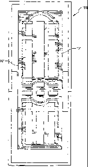
As shown in Figure 4, the core component 70 includes five
portions 80a, 80b, 80c, 80d, and 80e, which are relatively deeper than
intermediate segments 81a, 81b, 81c, and 81d (i.e., the portions 80 have a
greater dimension measured from opposite major surfaces in contact with
interior planar surfaces of the doorskins 31 and 31a). The relatively thin or
narrow segments 81 allow the core component 70 to continuously extend
through, and fit into, the constrictions 71-74. Thus, one advantage of the
methods and articles described herein is that it provides a single, pre-
consolidated article that can be placed on the interior of a doorskin, when
removed from the press, without substantial machining or routing or other post-
press surface forming being necessary.
CA 02477942 2004-09-01
WO 03/076148 PCT/US03/06633
-15-
The portions 80 of the core component 70 have a depth measured
by a perpendicular line segment from one exterior surface (not shown in Figure
4) of the portion 80 in contact with an interior surface of doorskin 31 to the
opposite exterior surface of the portion 80 in contact with an interior
surface of
doorskin 31a. (Such a measurement can be made along the line segment "A"
in Figure 4.) This depth can be, for example, in the range of about 3/4 inch
to
about 6 inches, preferably about 1 to 4 inches, more preferably about 1 to
about
2 inches, most preferably about 1 1/8 inches'to about 1 3/4 inches, e.g.,
particularly about 13/8 inches or 1 1/2 inches. The relatively thiii segments
81
can each have a depth, for example, in the range of about 1/8 to about 1/2
inch,
e.g., about 3/8 inch (measured along lines parallel to the line segment "A" in
Figure 4). The segments 81 preferably intersect with the portions 80 so that
the
depth differential therebetween is equally divided above and below the
segments
81, as shown in Figure 4. In the embodiment of Figure 4, the segments 80 and
81 intersect at an angle of about ninety degrees. However, these measurements
are variable depending, for example, upon (a) the type of product in which the
core component 70 is used, (b) the type of material used to make the core
component 70, and (c) the weight and sound insulation properties which are
desired in the fmal product. However, it is highly preferred that at least the
planar exterior surface portions 80 of the core are in substantially
continuous
contact with (e.g., secured to) the interior planar surfaces of the doorskins
31
and 31a.
Figure 5 shows an alternative embodiment which provides a door
having improved fire retardance. In this embodiment, the segments 80 and 81
intersect at an angle of less than ninety degrees, providing a core component
that more closely fits the contours of the depressions 36, 37 of the doorskins
31
and 31a. The angle of intersection of the segments 80 and 81 is preferably in
CA 02477942 2004-09-01
WO 03/076148 PCT/US03/06633
-16-
the range of about twenty to about ninety degrees, more preferably about
thirty
to about fifty degrees, and most preferably about forty degrees. The angle is
variable, however, depending upon the shape of the depressions 36 and 37.
It has been found that this arrangement produces a door having
improved fire retardance, particularly when the core component is made of a
soft board material. For example, a one and one-half inch thick door having
this arrangement can have a fire retardance rafing of about twenty minutes,
based on the aforementioned "Fire Endurance and Hose Stream Test"
performed by Warnock Hersey. The door achieves such a rating without
treatment with fire-retardant chemicals by slowing the ability of air to flow
through the space defmed by the doorskins 31, 31a, which in turn retards the
ability of flames to burn through the door. The greater mass provided by such
an arrangement may also help in providing such improved fire retardance.
Figure 6 illustrates another view of the core component 70. The
core component 70 has an outer edge 90, and includes an upper, substantially
planar major surface 91. The upper major surface 91 includes upper surface
portions 91a, 91b, 91c, 91d, 91e, 91f, and 91g The upper surface portion 91g
surrounds six relatively lower contoured portions or recesses 92a, 92b, 92c,
92d, 92e, and 92f. (The top surfaces of the recesses 92e and 92f define.the
top
2 0 surfaces of the segments 81a, 81b, 81c, and 81d shown in Figure 4.) The
recesses 92a-92f in turn surround the aforementioned upper surface portions
91a-91f.
The core component 70 can be placed in the interior of a
simulated six-panel hardboard doorskin because the recesses 92a-92f are
located
in the areas corresponding to the depressions outlining the panels in a six-
panel
CA 02477942 2004-09-01
WO 03/076148 PCT/US03/06633
-17-
door, for example the six-panel door of Figure 2. Referring to Figures 4 and
5, for example, the void created by the doorskins 31 and 31a can be filled by
a single core component 70 both at the constrictions 71-73 and the locations
where the depth of the door 30 is greatest. The narrow segments 8la-81d
(corresponding to the recesses 92a-92f of Figure 6) are located at the
constrictions 71-73, whereas the deeper segments 81a-81e (corresponding to the
upper surface portions 91e, 91f, and 91g of Figure 6) are located at the
full-thickness locations of the door 30. The planar upper major surface 91 of
the core component 70 is preferably attached to the bottom planar surface of
the
doorskin 31 by a suitable adhesive, as described below in greater detail.
Referring to Figure 6, the core component generally has smooth
and flat outer surfaces (e.g., the surface 91), surrounding the depressions
91a,
91b, 91c, 91d, 91e, and 91f. Optionally, the core component 70 can have a
texture on the portions of its outer surface 91 which will come into contact
with
or be glued to the inner surface of the man-made composite doorskins 31 and
31a. In some cases, such a texture can help in the adhesion of the core
component 70 to the doorskins. Further, it may in some cases be advantageous
to provide a contoured exterior surface, for example, an outer surface 91g
having a series of ribs protruding from the surface 91 and running along the
length or width of the core component 70.
According to a preferred embodiment, in addition to the recesses
or depressions 92a-92f being able to accommodate the depressions 32-37 of the
six-panel door 30 of Figure 2, the recesses 92 are at the same time able to
accommodate the depressions of various other styles of paneled doors (for
example, the depressions 12, 13 in the door 10 of Figure 1).
CA 02477942 2004-09-01
WO 03/076148 PCT/US03/06633
-18-
With this feature, the core component can be utilized in
conjunction with any doorskin that includes one or more depressions in
locations where the deeper portions 80 are located. A single, integrated
design
of core component (a so-called "master" or "universal" core component) can
then be utilized with multiple styles of paneled doorskins. The integration of
designs can be accomplished by taking into account all of the desired styles
of
doors; whenever one style of door dictates a contour or depression, the master
core component will be manufactured to have a recessed zone 92 at that
location. Figure 7 illustrates this feature of the invention wherein a single
core
component 100 can be used with numerous styles of molded doorskins, e.g.,
with either of the doors 10 and 30 shown in Figures 1 and 2. The core
component 100 of Figure 7 includes a recessed zone 101 that can accommodate
the depressions found in numerous different styles of paneled doors,
including,
for example, the contoured depressions 12 and 13 in Figure 1 and the
depressions 32-37 in Figure 2. This allows the door manufacturer to directly
interchange the core component 100 for use with any desired style of molded
doorskin, avoiding the need for the door manufacturer to stock an inventory of
multiple versions of the wood blanks.
Figure 8 illustrates a core component having an alternative
pattern that can accommodate various different styles of simulated paneled
doors (e.g., various four- and six-paneled doors). The patterns illustrated in
Figures 7 and 8 allow for doorskins (e.g., doorskins 10 and 30) having
depressions that are both straight (e.g., the depression 32 in Figure 2) and
curved (e.g., as in the depression portion 14 in Figure 1).
2 5 - Preferred methods of manufacturing a man-made hardboard door
product with a core component from composite soft board are described below.
CA 02477942 2004-09-01
WO 03/076148 PCT/US03/06633
-19-
It is understood, however, that, as described above, the core components can
be used with building members other than composite doors. In addition, the
core components can be used in conjunction with a doorskin or door face made
of materials other than fiberboard. Further, the cellulosic material selected
for
the core component is variable, depending upon the intended use of the core
component. Suitable types of fiberboard material include soft board,
medium-density fiberboard, hardboard, and oriented strandboard, as well as the
other materials described above.
An exemplative dry process useful for making the core
components described herein begins by first providing a suitable cellulosic
refined wood fibers having a moisture content of less than about 50 weight
percent, based on the weight of dry cellulosic fibers, preferably less than
about
weight percent based on the dry weight of the cellulosic fibers.
15 The refined cellulosic fiber is blended with a suitable
thermosetting resin binder. Any of the dry processes known in the art can be
used to blend the wood fiber with the binder resin, including blowline feeding
of the wood fiber and binder resin, or other mechanical means. For example,
the cellulosic fibers may be first coated with the thermosetting resin binder
by
20 blowline addition. Air turbulence causes the binder to disperse onto the
fibers.
The resin-coated fibers are randomly formed into a mat by air blowing the
coated fibers onto a support member to form a mat. The fibers, either before
or after formation of the mat, can optionally be subjected to an evaporation
step
that usually includes the application of heat, to cause a portion of the water
in
the fiber to evaporate.
CA 02477942 2007-09-19
-20-
The amount of binder resin used in the dry process to produce
the mat is generally about 0.5 to less than 20 weight percent based on the
weight of dry cellulosic fiber, but can vary depending upon the other process
parameters and intended use of the final product. Wood fibers are contained in
the core components in an amount of at least 80% by weight of the product,
preferably at least about 85% by weight based on the dry weight of the core
component. The binder resin is preferably used at about three to about fifteen
weight percent, and more preferably about three to about ten weight percent,
based upon the dry weight of the fibers. However, the amount is variable
depending upon the other process parameters and the desired final product.
Numerous useful binders for the manufacture of fiberboard are known in the
art, and include various modified and unmodified phenol-formaldehyde,
urea-formaldehyde, and/or isocyanate resins, including mixtures thereof.
Examples of suitable binders are disclosed, for example, in Kirk-Othmer
Encyclopedia of Chemical Technology, Vol. 15, pp. 176-208 (2nd Ed., 1970)
and U.S. Patent No. 5,367, 040 to Teodorczyk. Various modifiers can be added
to the binder resin, as known in the art.
The dry process mats useful for producing the core components
described herein are planar mats having at least about 80% refined,
fibrillated
cellulosic fibers, and preferably have an overall moisture content less than
about 20%, more preferably about 2% to about 16% by weight, based upon the
dry weight of the mat, prior to wetting the major surfaces of the mat.
In accordance with an important feature ofthe preferred process
for manufacturing core components, each mat surface molded to include one
or more depressions should have an average of at least 2% more moisture in the
CA 02477942 2004-09-01
WO 03/076148 PCT/US03/06633
-21-
upper and lower 10 % of the mat thickness than the average moisture content at
the center of the thickness of the mat prior to hot pressing (molding) in
order
to achieve sufficiently strong major surfaces for adhesively adhering
doorskins
to said major surfaces.
The mats preferably have a moisture content of about 2% to
about 16%, based on the dry weight of the mats, prior to increasing the
surface
moisture content in at least one major surface to, preferably, 4% to 20 %
greater
than the average moisture content at the center of the thickness of the mat.
In
a preferred embodiment, the mat comprising refined wood fiber, binder resin
and at least 2% moisture prior to surface wetting, can have a thickness of
about
2 to about 6 inches, for example, after pre-pressing the mat to a density of
' about 3-6 pounds per cubic foot in making a "pre-form"; however, this
thickness ' is widely variable depending upon the desired thickness of the
consolidated product (core component), the type of cellulosic material being
used, and pressing conditions, as well as other process parameters. The "pre-
form" has sufficient structural integrity to be inserted into the press or
mold
cavity, along with a lower screen that the fiber and binder mixture is
initially
deposited on.
To make the preform, in accordance with a preferred
embodiment, the fibers and binder resin are deposited onto a pervious support
structure, such as a screen, at a basis weight in the range of about 0.9
lbs./ft'
to about 3.0 lbs./ft2, more preferably in the range of about 1 lb./ft2 to
about 2
lbs./ft2, with a target of about 1.4 lbs/ft~, in order to manufacture core
components having a fmal density in the range of about 10 lbs./ft3 to about
30 lbs./ft3. The mat, as initially deposited on the support structure, may
have
a thickness up to about 12 to 15 inches and is pre-compressed (pre-pressed) in
CA 02477942 2004-09-01
WO 03/076148 PCT/US03/06633
-22-
any manner.known in the art to make the pre-form, such as by conveying the
mat between opposed rollers, or opposed belts that are spaced progressively
closer together down-line, to compress the mat to a thickness of about 6
inches
or less, preferably about 2-6 inches, more preferably about 3-4 inches in
thickness.
It is well known that fiberboards made by the dry prodess are not
as strong as fiberboards made by the wet or wet/dry processes (other
variables,
such as resin content and press times being the same) since refined,
fibrillated
fibers that are water-slurried will result in substantially greater fiber
entangling
than occurs in the dry process. It has been found, therefore, that the core
components described herein, when molded to include one or more interior,
molded depressions, and when pressed at commercially acceptable press times,
e.g., 2 to 30 minutes, preferably less than about 20 minutes, require an
additional pre-press surface wetting treatment in order to increase the
surface
density to a value greater than the surface density achieved in normal dry-
process fiberboard production.
Core materials made by existing dry-process fiberboard
production processes do not have sufficient surface strength so that a typical
3
foot by 7 foot core component produced by existing dry processes when fed into
a glue spreader - an apparatus that rolls glue over the planar surface area
surrounding the interior depressions - will peel over at least a portion of
the
planar surfaces being coated with adhesive.
It has been found that there are two primary reasons for surface
peeling of dry process core components during the above-described post-press
glue application step: (1) heat transfer into the dry process mat during
CA 02477942 2004-09-01
WO 03/076148 PCT/US03/06633
-23-
consolidation into a core component is inadequate since little to no water is
available to more efficiently transfer heat throughout the mat; and (2) due to
the
inefficient heat transfer to the center of the mat, a surface portion of the
mat
becomes hot enough to cure the resin at the surface of the core component
before the mat is compressed to its fmal thickness, resulting in a surface
layer
that does not bond sufficiently to the underlying fibers.
In order to overcome the above-mentioned surface peeling
problems, applicants have found that by adding water to at least one major
surface of the dry-process formed mat prior to pressing, so that surface
layer(s)
(a wetted surface 10% of the thickness of the mat when inserted into the mold
cavity) have an average of at least 2% by weight more moisture than an average
moisture content at the center of the thickness of the mat, for example, 2% to
about 32 % more moisture in the surface layer(s) than in the center of the mat
thickness, preferably at least 4% by weight more moisture, more preferably 4-
30 % by weight more moisture in the surface layers, most preferably about 12-
18 % more moisture in the surface layer(s), based on the dry weight of the
mat,
with the mat to be pressed having, prior to surface wetting, a preferred
moisture
content of 2-16% by weight, based on the dry weight of the mat.
The additional surface water lengthens the time it takes for the
surface resin to cure during the press cycle, so that the mat is compressed to
its
final dimensions before the thermosetting resin, including the surface resin,
is
completely cured, thereby creating a strong, relatively uniform bond
throughout
the thickness of the core component. By this "pre-press" water addition to at
least one major surface of the mat, the pre-press wetted surface layer of the
core component does not peel away from the core component during adhesive
application to the planar stile and rail portions of the core component, and
the
CA 02477942 2007-09-19
-24-
post-press core component has added surface strength and density for any core-
contacting post-press surface treatment, particularly an adhesive coating
step.
Optionally, a surfactant or penetration aid can be added to the water applied
to
the core component surfaces for better, more uniform distribution of the water
into the upper and/or lower major surfaces of the mat. Suitable surfactants or
penetration aids, preferably also containing a mold release agent for easier
removal of the core components from the mold cavity, applied in an amount of
about 1-10% by weight of the surface-applied water, preferably about 3-7%,
more preferably about 2-5% by weight, and most preferably about 2.5% by
weight of the applied surface water, include Wurtz (trade-mark) PAT-529/S;
SURFYNOL (trade-mark) 104H surfactant (75% by weight tetramethyl-5
-decyne-4,7-diol and 25% by weight ethylene glycol); TRITON X-100 (trade-
mark) surfactant (97% by weight octylphenoxypolyethoxy-ethanol and 3%
polyethylene glycol); and RHODASURF DA-639 (trade-mark)
(polyoxyethyoxylated (6) isodecyl alcohol); Akzo Nobel Coatings, Inc. Product
No. 819-C029-4 clear post-press sealer; and the like.
The additional surface water can be applied in any suitable
manner such as spraying, via steam surface contact, or any known coating
technique.
The pre-form is surface wetted on at least one major surface,
preferably both major surfaces, prior to placing the pre-form into the mold
cavity such that the wetted major surface layer(s) have an average moisture
content at least 2% greater than the average moisture content of the mat at a
center of its thickness, preferably 4-30% more moisture, on average, in the
surface layer(s) than the average moisture content of the pre-form along a
plane
of the pre-form at the center of its thickness (hereinafter called
the"thickness
CA 02477942 2004-09-01
WO 03/076148 PCT/US03/06633
-25-
center"). The surface layer or layers are hereby defmed as an outer thickness
of a wetted major surface extending into the mat, from the wetted major
surface
of the pre-form, a depth of 10% of the pre-form thickness.
The water applied to one or both major surfaces of the pre-form
is applied in an amount sufficient to achieve the increased moisture content
of
at least 2% more in the surface layer(s) than at the thickness center,
preferably
about 4% to about 30% more moisture, more preferably about 8% to about
20 % more moisture in the wetted surface layer(s). The water applied to one or
both major surfaces of the pre-form, or during pre-pressing in making the pre-
form, should penetrate less than 20% of the depth of the pre-form measured
into the pre-form from the wetted surface, preferably 10-15 % depth
penetration. Small amounts of water, e.g., less than 20% by weight, can
penetrate more deeply so long as the surface 10% of the thickness of the pre-
form has an average of at least 2% by weight more moisture than the average
moisture content at the thickness center. Generally, water is applied in an
amount of about 5 to 20 grams/ftZ of surface area, preferably about 7 to 15
grams/ftZ, more preferably about 10 grams/ft' over both major surfaces. Higher
moisture contents in the surface layers provides a stronger, denser surface to
the
core components and increases the compressibility of the mat in the press or
mold cavity used to form the core component as a non-laminated, unitary
structure, having one or more depressions in one, or preferably both major
surfaces. It is most, preferred that the pre-form have an average moisture
content at the center thickness of about 5-8 % by weight, based on the dry
weight of the pre-form, with an average moisture content in the upper and
lower 10 % of the pre-form thickness (in the wetted surface layers) of about
8%
CA 02477942 2004-09-01
WO 03/076148 PCT/US03/06633
-26-
to about 20 % by weight moisture, with a target surface layer moisture content
of about 12-18 % moisture, particularly about 15 % moisture, based on the dry
weight of the pre-form.
In accordance with one important embodiment, the lower surface
layer of the pre-form (at the screen-contacting major surface) is wetted by
contacting the lower surface of the mat with steam at a sufficiently low
pressure
that the steam is condensed on the mat fibers oiily about 10-20% of the depth
of the pre-form, and is applied to the lower surface of the mat during the
pre-press process (while the pre-form is being made) or upon completion of the
pre-form, and prior to placing the pre-form into the mold cavity. Since the
pre-
compression of the mat is performed while the lower surface of the mat is
being
carried by a water-pervious screen, steam is easily passed through the screen
across the entire width of the lower surface as the mat is being compressed in
a continuous process line used to make the pre-form.
The undersurface of the mat has been found to dry at a faster rate
than the upper surface of the mat during loading of a plurality of mats into a
multi-panel hot press, since the undersurface of the mats, particularly mats
first
loaded, are in contact with a lower mold surface still hot from a previous
pressing prior to closing the press to contact the upper surface with the hot,
upper, contoured mold die. In order to maintain a higher moisture content on
the lower mat surfaces similar to the moisture content on the upper mat
surfaces
prior to closing the mold cavity, therefore, the loss of moisture on the lower
mat surface prior to pressing can be compensated for by applying more water
to the lower surface of the mats than on the upper surface; or by a short
steam
surface contact time at a small enough steam pressure to prevent steam from
penetrating more deeply into the lower major surface more than about 20% of
CA 02477942 2004-09-01
WO 03/076148 PCT/US03/06633
-27-
the thickness of the mat; and/or by increasing the surface density and surface
strength of the lower surface of the consolidated core components in a post-
press step, such as a surface treatment capable of increasing the strength of
the
lower surface of the consolidated core component, e.g., coating the lower core
component surface with a sealer, such as polyvinyl acetate, e.g., Akzo
Coatings
Product No. 610-C020-264. The sealer is preferably applied to a lower surface
of the core component in an amount of active sealer of about 1-10 grams/ft2 of
lower core component surface area, more preferably about 2 to about 6 grams
of active sealer per square foot of surface area, most preferably about 4
grams
of polyvinyl acetate per square foot of the lower major surface of the core
component. Suitable post press sealers are well known in the art and include,
for example: Akzo Nobel Coatings, Inc. acrylic, sealers, Product Nos. 610-
C020-178 and 610-C020-179; Akzo Nobel Coatings, Inc. clear post-press
sealer, Product No. 819-C029-4; and the like.
It has been found that the surface water addition slows the cure
of the resin at the heated surface of the mat sufficiently to prevent surface
layer
peeling of the finished core component during a core-component post-press
surface treatment step, particularly adhesive application, without
detrimentally
slowing the overall press time needed to manufacture the core components
described herein. Ideally, even after the above-described surface water
addition, the core 'components can be completely consolidated in the heated
press, with complete cure of the binder resin, at overall press times of about
minutes or less, preferably about 10 minutes or less, more preferably about
2 to 6 minutes, usually in about 4 minutes.
2 5 Examples of resins having suitable gel times capable of
eliminating the above-described, undesirable "precure" (premature surface
CA 02477942 2004-09-01
WO 03/076148 PCT/US03/06633
-28-
resin curing) while having essentially complete thermosetting resin curing
throughout the core component, for overall core component strength, in a
sufficiently short press time for commercial manufacture, are identified
below.
The following exemplary resins that have cure rates of slow, medium, and fast
provide the indicated core component properties:
SLOW PHENOLIC RESIN, e.g., GEORGIA PACIFIC 99C28
Gel time - 57 minutes
Slow resin gives less precure, better surfaces. Pre-press water surface
treatment is less critical. Slow cure gives lower overall strength
at the same press time, press time would likely be lengthened to
7-15 minutes. Used when surface strength needs to be improved
for a particular application.
MEDIUM PHENOLIC RESIN, e.g., GEORGIA PACIFIC 169C21
Gel time - 29 minutes
Preferred embodiment: Good surfaces in combination with pre-press
water surface treatment and good strength at currently planned
four minute cycle.
FAST PHENOLIC RESIN, e.g., GEORGIA PACIFIC 106C77
Gel time - 20 minutes
Fast resin gives good overall strength while allowing shortest cycles.
Fast resin gives poorest surfaces. Pre- and post-press surface
treatments essential to adequate surface strength.
CA 02477942 2004-09-01
WO 03/076148 PCT/US03/06633
-29-
Once placed in the press, the mats are molded under heat and
pressure. The press temperature is preferably in the range of about 275 F to
about 550 F (and more preferably about 390 F to about 450 F), and the press
pressure is preferably in the range of about 400 psi to about 850 psi (more
preferably 600 psi to about 800 psi). The press time is generally in the range
of about 20 seconds to about 30 minutes (more preferably in the range of
about 1 minute to about 10 minutes, most preferably about 2 minutes to about
6 minutes). However, these conditions are variable depending upon the desired
fmal product and that those of ordinary skill in the art will be able to make
modifications based upon the desired fmal product. When exposed to this heat
and pressure, the thermosetting resin will be cured and the mat will be
compressed into an integral consolidated structure. The overall density of the
soft board core component is preferably in the range of about 10 lbs/ft3 to
about
30 lbs/ft3 (more preferably about 12 to about 25 lbs/ft3, and most preferably
about 13 to about 18 lbs/ft3). The density of the pressed soft board (core
components) vary significantly between the areas that include molded
depressions and the planar areas surrounding the depressions. The density in
both locations depend -upon the basis weight of the mat being pressed, the
desired ultimate thickness of the core components, and the depth of the
depressions. However, in a single core component, the variation of density at
different depressions, and the variation of density at different planar areas
surrounding the depressions should be minimal. The overall specific gravity
of such an article can be in the range of about 0.2 to about 0.6, preferably
about
0.2 to about 0.5, and most preferably about 0.2 to about 0.3, with the
specific
gravity at the depressions being as high as about 1.2, and the specific
gravity
at the thicker, planar areas being generally about 0.2 to 0.5.
CA 02477942 2004-09-01
WO 03/076148 PCT/US03/06633
-30-
According to a preferred method, a dry process pre-form mat
having a thickness of about 2 to 6 inches is pressed to final dimensions,
e.g.,
1 3/8 or 1 1/2 inches in thickness, in a single hot pressing operation, while
forming doorskin depression-receiving recesses in one or both major surfaces.
In accordance with another, less-preferred embodiment, a plurality of soft
board
"blanks" are pressed from cellulosic mats, and a pressed soft board blank can
be combined with (e.g., laminated to) additional prepressed blanks to achieve
a desired thickness. The softboard laminated* wood blanks are preferably
manufactured to a thickness of about 3/8 inch each. The blanks can be
laminated together to form any desired final thickness, preferably in the
range
of about 3/4 inch to about 3 inches, and more preferably about 1 inch to about
1 3/4 inches, e.g., about 1 1/8 inches or about 1 1/2 inches. Any suitable
adhesive, such as casein or polyvinylacetate, can be used to bond the
laminates
together.
A pattern doorskin depression-receiving recess, or depressions,
such as described above, is molded to a depth of about 1/2 inch into the soft
board core component on each of the major surfaces of the core component
during consolidation, to have the configuration shown in Figure 6 or Figure 7,
for example. The distance between the molded depressions on opposite sides
of the core component preferably is in the range of about one-eighth to about
one-half inch.
The recessed depressions molded into the surfaces of the core
components can have a bead or bead-and-cove design, e.g., as can be provided
with the zones 12 and 13 of the doorskin 11 of Figure 1. This molded
depressing can be utilized in conjunction with the above-described method for
CA 02477942 2004-09-01
WO 03/076148 PCT/US03/06633
-31-
providing a "master" core component that can be used with multiple styles of
doorskins.
Once the core component has been produced, it preferably will
be assembled along with two doorskins and framing structure as described
above. Although any type of doorskin can be utilized in accordance with the
inventive method and article, conventional hardboard doorskins having a
thickness of about one-eighth inch are preferred.
Many different sizes of core components can be produced in
accordance with the invention. For example, a core component having a
thickness of about one and one-eighth inch can be placed on the interior of a
doorskin assembly having an external thickness of about 1 3/8 inches. Such a
door is preferably used for interior home applications. A core component
having a thickness of about one and one-half inch can be placed on the
interior
of a doorskin assembly having an exterior thickness of about 1 3/4 inches.
Such a door provides greater mass and protection, and can be used as an
interior door or ari exterior door, and for various commercial and industrial
door applications.
Preferred adhesives for bonding the core components to
doorskins include, for example, casein or polyvinylacetate, and their
derivatives. The adhesive is preferably placed at, all locations where the
doorskins and/or the framing members come into contact with the core
component 70, e.g., at all planar surfaces surrounding the depressions. The
inventive door preferably uses a rail and stile supporting structure. However,
it is contemplated that the need for a lock block might be avoided through the
use of the inventive process.
CA 02477942 2004-09-01
WO 03/076148 PCT/US03/06633
- 32 -
As described above, the inventive core component preferably
provides a door product or other building member, with beneficial weight and
sound insulation properties that is not as time-consuming or labor intensive
to
manufacture as known core components. The core component also can provide
substantial structural stability. A door comprising fiberboard doorskins and
the
inventive core component will preferably have the same feel and ability to
swing shut (e.g., as a result of a desirable weight) as a natural wood door.
Further, the sound insulation and fire retardance properties of the door are
preferably greatly improved over the properties of a similar door which lacks
the inventive core component.
The foregoing description is given for clearness of understanding
only, and no unnecessary limitations should be understood therefrom, as
modifications within the scope of the invention will be apparent to those
skilled
in the art.