Note : Les descriptions sont présentées dans la langue officielle dans laquelle elles ont été soumises.
CA 02484679 2004-10-14
PLASMA-CUTTING TORCH WITH
INTEGRATED HIGH FREQUENCY STARTER
BACKGROUND OF THE INDENTION
The present invention relates generally to plasma cutting systems and, more
particularly, to a system for plasma cutting wherein a high-frequency starting
eircuit is
integrated within a plasma-cutting torch. As such, the amount of high
frequency, high
voltage power necessary for starting the plasma cutter is reduced and the
amount of wires
and circuitry exposed to the power source is reduced. Furthermore, the plasma-
cutting
torch may be retro-fitted to power sources regardless of a startup
configuration for which
the power source was designed.
Plasma cutting is a process in which an electric arc is used to cut a
workpiece. Plasma
cutters typically include a power source, a gas supply, and a torch. The torch
or plasma torch is
used to create and maintain the arc and plasma that perform the cutting. The
plasma cutting
power source receives an input voltage from a transmission power line or
generator and provides
an output voltage to a pair of output terminals, one of which is connected to
an electrode and the
other of which is connected to the workpiece.
The air supply is used with most plasma cutters to help start the arc, provide
the plasma
gas to the torch, and cool the torch. A nnovable or fixed electrode serves as
a cathode and a fixed
nozzle serves an anode. The air supply moves the electrode and as the
electrode moves away
from the nozzle, it opens the nozzle, and a plasma jet is created. The plasma
jet causes the arc to
transfer to the work piece, and thus initiates the cutting process. In other
plasma cutting systems,
a high frequency starter is used to initiate the cutting process.
Most plasma cutting systems implement one of two methods of initiating the
plasma cutting arc: high frequency (HF~ starting and the above-described
contact starting.
Contact start torches use a moving electrode or nozzle to create an initial
spark to ionize
the cutting gas and generate a pilot arc. A contact start torch begins with
the electrode
1
CA 02484679 2004-10-14
and nozzle in contact causing a short circuit, until the gas reaches the
short, which blows
the electrodes and/or nozzle apart to create a spark across the newly formed
gap. The
spark ionizes the gas thereby enabling current to flow across the newly formed
gap
between the nozzle and the electrode and create a pilot arc. While contact
starting is a
common method of initiating a plasma cutting process, it does present
drawbacks.
Specifically, the moving electrode and/or nozzle are particularly susceptible
to wear.
Furthermore, the designs are quite complex and are susceptible to misassembly,
misalignment, or breakdown of the moving parts.
In contrast, HF starting is a method of generating a pilot arc without moving
parts
or the wear associated with shorting and breaking the nozzle and electrode. To
perform
HF starting, a plasma torch is connected to a power source having an HF
starting circuit.
The circuit typically includes a high-voltage transformer, capacitors for
power
conditioning, and a gap assembly to generate a high-voltage spark at the torch
electrode.
When sufficient power is transferred from the power source to the torch, a
spark fires
from the electrode and ionizes gas between the electrode and nozzle. This
ionization
enables current to flow across the air gap between the nozzle and the
electrode. The
result is a pilot arc to initiate cutting.
HF starting generally requires a voltage on the order of 3.SkV to SkV to
generate
the ionizing spark. As such, the high-voltage transformer and coupling coil
required to
operate at such a voltage are relatively large, which can add to the size of
the plasma-
cutting system making portability cumbersome.
The high voltage must also be translated a considerable distance from the
power
source to the torch. It is not uncommon for distance between the power source
and torch
to reach distances of over fifty feet, resulting in significant losses. This
problem is
compounded as' the distance from the power source to the torch varies as the
cord
connecting the two components is moved and stretched. Furthermore, extended
lengths
2
CA 02484679 2004-10-14
of the power cord or cable may be susceptible to relatively harsh working
conditions that
may negatively affect the HF power being transferred to the torch. For
example, plasma
cutters are commonly operated within large manufacturing environments or at an
in-field
site. Adding to these typically callous operating environments, the HF
starting circuits
typically generate a considerable amount of electrical noise. Such noise can
be
particularly undesirable in sensitive manufacturing processes where electrical
interference can impact the operability of the manufacturing process.
Additionally, HF starting systems are mutually exclusive from contact starting
systems. That is, because both the power source and the torch must be
specifically
tailored to the starting method, contact and HF starting power sources and
torches may
not be interchanged without modifications.
It would therefore be desirable to design a plasma cutting system that is
capable
of generating a pilot arc while reducing the aforementioned drawbacks of
traditional
contact and HF starting circuits. Specifically, it would be desirable to
design a plasma
cutting system with a HF starting circuit with reduced voltage requirements.
Additionally, it would be desirable fox the system to be able to be
retrofitted to existing
plasma cutting systems regardless of whether the system is designed for
contact or HF
starting.
3
CA 02484679 2004-10-14
BRIEF DESCRIPTION OF THE INVENTION
The present invention is directed to a system for plasma cutting that
overcomes
the aforementioned drawbacks. Specifically, the present invention provides a
system of
HF starting a plasma cutting process with reduced voltage requirements.
Additionally,
the present invention reduces component interdependency and may be integrated
with
existing plasma cutting systems.
Therefore, in accordance with one aspect of the present invention, a plasma
cutting torch
includes a torch body, an output electrode disposed in the torch body and a
plasma cutter starting
circuit disposed in the torch body and configured to generate a pilot arc at
the output electrode.
In accordance with another aspect of the present invention, a manufacturing
kit is
disclosed that includes a plasma cutting torch configured to operatively
engage a power source
and a pilot arc starting circuit configured to supply the plasma cutting torch
with a pilot arc
independent of a starting configuration of the power source.
In accordance with another aspect of the present invention, a plasma cutting
assembly is
disclosed that includes a power source, a plasma cutting torch, and a starter
circuit disposed
within the plasma cutting torch and configured to supply the plasma cutting
torch with a pilot arc
independent of a starting mechanism of the power source.
Various other features, objects and advantages of the present invention will
be
made apparent from the following detailed description and the drawings.
4
CA 02484679 2004-10-14
BRIEF DESCRIPTION OF THE DRAWINGS
The drawings illustrate one preferred embodiment presently contemplated for
carrying out the invention.
In the drawings:
Fig. 1 is a perspective view of a plasma cutting system incorporating the
present
invention.
Fig. 2 is a cross-sectional view of a plasma cutting torch in accordance with
the
present invention.
Fig. 3 is a graphic representation of a plasma cutting starting system
operable with
the plasma cutting system shown in Fig. 1.
CA 02484679 2004-10-14
DETAILED DESCRIPTION OF THE PREFERRED EMBODIMENT
The present invention is directed to a system for starting a plasma cutting
process.
Specifically, the present invention provides a system of HF starting a plasma
cutting
process with reduced voltage requirements. Additionally, the present invention
reduces
component interdependency and may be retro-fitted to power sources configured
for
contact stating plasma cutters:
Referring to Fig. l, a plasma cutting system 10 is shown. The plasma cutting
system is a
high voltage system with maximum open circuit output voltages ranging .from
approximately 230
Volts Direct Current (VDC) to over 300 VDC. The plasma cutting system 10
includes a power
source 12 to condition raw power and regulate/control the cutting process.
Specifically, the
power source includes a processor that, as will be described, receives
operational feedback and
controls the plasma cutting system 10 accordingly. Power source 12 includes a
lifting means,
such as a handle 14 which effectuates transportation from one site to another.
Connected to the
power source 12 is a torch 16 via cable 18. The torch 16 is defined at least
by a torch body or
housing 17 enclosing a plasma-cutting electrode encompassed in a consumable
assembly 19.
Typically, the consumable assembly 19 has an insert formed therein that
exhibits preferable
electrical properties. That is, the insert is preferably formed of hafnium or
zirconium. The cable
18 provides the torch 16 with power and serves as a communications link
between the torch 16
and power source 12. The cable 18 contains two conductive paths. One
conductive
communications link or conductive path is dedicated to the transfer of power
to energize the
plasma-cutting electrode and the other conductive path is dedicated to the
transfer of feedback to
the power source 12. In an alternative embodiment, the cable 18 contains one
conductive path
between the torch 16 and power source 12 to transfer both operational feedback
and power.
Specifically, a single conductive path is contained within the cable 18 that
simultaneously
transfers power and feedback from the plasma torch regarding the plasma
cutting process.
Also connected to power source 12 is a work clamp 20 which is designed to
complete the
circuit for a workpiece knot shown) to be cut. Connecting work clamp 20 to the
power source 12
is a cable 22 designed to provide a return path for the cutting current from
the torch through the
workpiece and the work clamp 20. Extending from a rear portion of power source
12 is power
6
CA 02484679 2004-10-14
cable 24 having plug 26 for connecting the power source 12 to a portable power
supply 28 or a
transmission power receptacle (not shown). Power source 12 further includes an
ON/OFF switch
30.
To effectuate cutting of a workpiece, torch 16 is placed in: close proximity
to a workpiece
connected to clamp 20. A user may then activate a trigger lock (not shown), in
response to which
a feedback signal is sent from a trigger sensor disposed within the torch 16
and connected to the
trigger lock in the torch 16, via cord 18. Upon reaching the power source 12,
the feedback is
processed by a processor disposed within the power source. Upon pressing the
trigger switch,
another feedback signal is sent from the trigger sensor disposed within the
torch 16 to the
processing unit of the power source 12.
Once the trigger switch signal is processed, the power source processing unit
causes
power to be sent to the torch 16 to initiate a pilot arc. As will be
described, the power source 12
transmits power via cable 18 to the torch 16. The HF starting circuit in the
torch 16 is configured
to supply a high-frequency, high-voltage power to the consumable assembly 19
of the torch 16
independent of a starting configuration of the power source 12. That is, the
power source 12
delivers normal operational power to the torch 16 upon initiation and the HF
starting circuit of the
torch 16 provides the voltage necessary to generate the pilot arc that is
required to begin the
plasma cutting process. To assist in generating a pilot arc and to enable
generation of a plasma
for cutting, gas is supplied to the torch 16 from a pressurized gas source 39.
Referring now to Fig. 2, a cross-section of a plasma cutting torch 16 is
shown.
Plasma torch I6 is defined by a torch 'body 36 that is designed to receive a
shield cup 38.
Shield cup 38 is connected to torch body 36 so as to define a gas chamber 40
that, as will
be described in greater detail below, allows for the generation and passage of
a plasma.
Centrally disposed within gas chamber 40 and connected to torch body 36 is
consumable
or electrode 42. Consumable 42 is removably connected to torch body 36 and is
specifically designed for a particular plasma cutting process. That is, torch
16 is
constructed such that various consumables may be interchangeably connected
depending
upon the particulars of a plasma cutting process to be carried out.
7
CA 02484679 2004-10-14
Connected to shield cup 38 is tip 44 that is constructed to form a nozzle 46.
In
operation, gas is injected into chamber 40 via passages 48 and is heated to a
plasma. The
plasma is then forced out of the chamber through nozzle 46 and out of the tip
44 via
opening or aperture 50. Nozzle 46 is designed to focus the velocity as well as
the heat of
an arc that is created between a workpiece (not shown) and electrode 42.
Electrode 42 is
constructed such that the arc extends across an arc path 52 out of the
consumable through
opening 50.
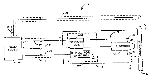
Refernng now to Fig. 3, a graphic representation of the plasma cutting
starting
system referred to in Fig. 1 is shown. The power source 12 includes three
electrical
connections 54-58 to the torch 16 and workpiece 60. Specifically, the
workpiece 60 is
connected to a first positive polarity electrical connection 58 via a clamp
61.
Furthermore, a negative polarity electrical connection 54 and a second
positive polarity
electrical connection 56 is made via cable 18 between the power source and an
HF
starting circuit 62 disposed within the torch 16. A second positive polarity
electrical
connection is made between power source 12 and workpiece 60 via cable 22.
The negative and second positive polarity electrical connections 54, 56 are
connected to a coupling coil 66, which, in turn, is electrically connected to
the
consumable assembly 19. Specifically, the negative polarity connection is
delivered from
the coupling coil 66 to a cutting electrode 42 and the positive polarity
connection is
delivered from the coupling coil 66 to the tip 44. Connected to the coupling
coil 66 is a
high voltage transformer 64. The high voltage transformer 64 is controlled by
a control
line 65. The control line 65 serves to cause the HF starting circuit 62 to
initiate. While
the control line 65 is shown for exemplary purposes as connected to the power
source 12,
it is also contemplated that control commands may be generated and
communicated
Within the torch 16. As such, the control line 65 would originate within the
torch 16 and
8
CA 02484679 2004-10-14
terminate at the high voltage transformer 64, thereby remaining within the
torch 16 and
minimizing the length of the control line 65.
When a plasma cutting process is initiated, operational power is delivered
from
the power source 12 to the HF starting circuit 62. The HF starting circuit 62
steps the
voltage up to a high-frequency, high-voltage power and delivers the power to
the
electrode 42. The high-frequency, high-voltage power causes a spark to fire
between the
electrode 42 and the tip 44 and ionizes gas within the gap between the
electrode 42 and
the tip 44. The ionized gas enables current to flow across the air gap between
the nozzle
46 and the electrode 42. The result is a pilot arc, which is used to initiate
cutting.
Placing the HF starting circuit 62 within the torch 16 has a number of
advantages.
Examples of some of these advantages follow. First, an electrical loop 72
created from
the HF starting circuit 62 to the consumable assembly 19 and back to the HF
starting
circuit is a fixed distance and greatly reduced in length. That is, in systems
where the HF
starting circuit is disposed within the power source 12, high-frequency, high-
voltage
power must be transmitted via cable 18, which is typically fifty feet or
greater in length.
As such, a loop of over 100 feet is created from the power source 12 to the
consumable
assembly 19 and back. Furthermore, the exact distance of the loop may vary
depending
upon the length of cable 18. ~n the other hand, by placing the HF starting
circuit 62
within the torch 16, the high voltage transformer 64 is within approximately
twelve
inches of the consumable assembly 19. Therefore, high-frequency, high-voltage
power is
transmitted a fixed distance of a matter of inches through the electrical loop
72.
As a result of the reduced and fixed distance of the electrical loop 72,
losses are
reduced. That is, losses are reduced due to the lowered resistance of the loop
72 as
compared to the significant-in-length electrical loops of plasma cutting
systems having an
HF starter circuit in the power source. Furtrrermore, since the size of the
loop 72 is fixed,
the HF starting circuit 62 can be calibrated to deliver optimal power to the
consumable
9
CA 02484679 2004-10-14
assembly 19 rather than an overpower necessary to account for fluctuations in
the loop
distance. As such, electronic noise due to the transmission of the high-
frequency, high-
voltage power to the consumable assembly I9 is significantly reduced. The
electronic
noise generated by the transmission of the high-frequency, high-voltage power
around the
loop 72 within the torch is relatively negligible.
Furthermore, by placing the HF starting circuit 62 in the torch 16, the high
voltage
transformer 64 is within approximately twelve inches of the consumable
assembly 19.
Due to this close proximity of components, the voltage necessary to generate a
pilot arc is
reduced by approximately a factor of five. Accordingly, by placing the HF
starting
circuit 62 in the torch 16, the high voltage transformer 64 and coupling coil
66 may be
reduced by approximately a factor of fave. Therefore, by disposing the HF
starting circuit
62 within the torch 16, a Iower voltage is necessary to generate a pilot arc
and, as such,
the components of the HF starting circuit 62 may be reduced in size.
Also, by having the HF starting circuit within the torch 16, the torch 16 is
no
longer dependent upon the power source 12 for startup. As such, the torch 16
may
operate with any power source regardless of the startup method that the power
source was
designed to perform. That is, the torah 16 can be retrofitted to power sources
designed
for HF or contact start plasma torches because, even at startup, the torch 16
only requires
operational power from the power source 12. Therefore, the startup
interdependency
between the torch 16 and the power source 12 is removed and the torch 16 may
be readily
interchanged with various power source configurations.
It is contemplated that the above described invention be embodied in a wide
variety of plasma cutting torches. Specifically, the invention is equally
applicable to
manually controlled cutting torches as well as robotic or computer controlled
cutting
torches. ' ' '
CA 02484679 2004-10-14
It is further contemplated that the current invention be embodied in a plasma
cutting torch
that includes a torch body, an output electrode disposed in the torch body and
a plasma cutter
starting circuit disposed in the torch body and configured to generate a pilot
arc at the output
electrode.
It is also contemplated that the present invention be embodied as a
manufacturing kit that
includes a plasma cutting torch configured to operatively engage a power
source and a pilot arc
starting circuit configured to supply the plasma cutting torch with a pilot
arc independent of a
starting configuration of the power source.
Additionally, it is contemplated that the current invention be embodied in a
plasma
cutting assembly that includes a power source, a plasma cutting torch, and a
starter circuit
disposed within the plasma cutting torch, and configured to supply the plasma
cutting torch with a
pilot arc independent of a starting mechanism of the power source.
The present invention has been described in terms of the preferred embodiment,
and it is
recognized that equivalents, alternatives, and modifications, aside from those
expressly stated, are
possible and within the scope of the appending claims.
11