Sélection de la langue

Search

Sommaire du brevet 2489655 

Énoncé de désistement de responsabilité concernant l'information provenant de tiers

Une partie des informations de ce site Web a été fournie par des sources externes. Le gouvernement du Canada n'assume aucune responsabilité concernant la précision, l'actualité ou la fiabilité des informations fournies par les sources externes. Les utilisateurs qui désirent employer cette information devraient consulter directement la source des informations. Le contenu fourni par les sources externes n'est pas assujetti aux exigences sur les langues officielles, la protection des renseignements personnels et l'accessibilité.

Disponibilité de l'Abrégé et des Revendications

L'apparition de différences dans le texte et l'image des Revendications et de l'Abrégé dépend du moment auquel le document est publié. Les textes des Revendications et de l'Abrégé sont affichés :

  • lorsque la demande peut être examinée par le public;
  • lorsque le brevet est émis (délivrance).
(12) Demande de brevet: (11) CA 2489655
(54) Titre français: MONTAGE DU ROTOR D'UNE TURBINE A GAZ
(54) Titre anglais: MOUNTING OF THE ROTOR OF A GAS TURBINE
Statut: Réputée abandonnée et au-delà du délai pour le rétablissement - en attente de la réponse à l’avis de communication rejetée
Données bibliographiques
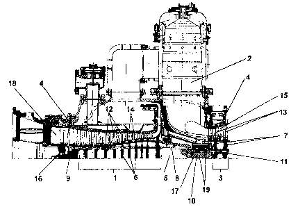
(51) Classification internationale des brevets (CIB):
  • F01D 25/16 (2006.01)
  • F01D 03/00 (2006.01)
  • F02C 07/06 (2006.01)
  • F16C 35/02 (2006.01)
(72) Inventeurs :
  • ASCHENBRUCK, EMIL (Allemagne)
  • BLASWICH, MICHAEL (Allemagne)
  • KLEINEFELDT, ANDREAS (Allemagne)
  • ORTH, ULRICH (Allemagne)
(73) Titulaires :
  • MAN TURBO AG
(71) Demandeurs :
  • MAN TURBO AG (Allemagne)
(74) Agent: GOWLING WLG (CANADA) LLP
(74) Co-agent:
(45) Délivré:
(22) Date de dépôt: 2004-12-07
(41) Mise à la disponibilité du public: 2005-06-15
Requête d'examen: 2007-03-09
Licence disponible: S.O.
Cédé au domaine public: S.O.
(25) Langue des documents déposés: Anglais

Traité de coopération en matière de brevets (PCT): Non

(30) Données de priorité de la demande:
Numéro de la demande Pays / territoire Date
103 58 953.8 (Allemagne) 2003-12-15

Abrégés

Abrégé anglais


The rotor (5) of a gas turbine containing a compressor part (1) and a turbine
part (3) is
mounted in an axial thrust bearing (19) and in two radial journal bearings
(16, 17). One of the
bearings is a journal bearing (16) arranged in the intake area of the
compressor part (1) and the
other journal bearing (17) together with the thrust bearing (19) is arranged
in the area of the
turbine part (3).

Revendications

Note : Les revendications sont présentées dans la langue officielle dans laquelle elles ont été soumises.


WHAT IS CLAIMED IS:
1. An arrangement for mounting the rotor of a gas turbine having a compressor
part and
a turbine part, the arrangement comprising:
the rotor mounted in an axial thrust bearing and in two radial journal
bearings, one of said
journal bearings being arranged in an intake area of the compressor part and
another of said
journal bearings being arranged in an area of the turbine part and said thrust
bearing being
arranged in the area of said turbine part.
2. An arrangement for mounting a rotor of a gas turbine in accordance with
claim 1,
wherein said thrust bearing is arranged in the area of the turbine part
together with said another
of said journal bearings.
3. An arrangement for mounting a rotor of a gas turbine in accordance with
claim 1,
wherein tilting segment bearings are arranged as said axial thrust bearing and
two radial journal
bearings.
4. An arrangement for mounting a rotor of a gas turbine in accordance with
claim 1,
wherein sliding surface bearings are arranged as said axial thrust bearing and
two radial journal
bearings.
5. An arrangement for mounting a rotor of a gas turbine in accordance with
claim 1,
8

wherein said magnetic bearings are used as said axial thrust bearing and two
radial journal
bearings.
6. An arrangement for mounting a rotor of a gas turbine in accordance with
claim 1,
wherein sliding surface bearings are arranged as said journal bearings and a
tilting segment
bearing is provided as said thrust bearing.
7. An gas turbine arrangement, the arrangement comprising:
a rotor with cooperating gas turbine compressor part and turbine part;
an axial thrust bearing;
a first radial journal bearing; and
a second radial journal bearing, said rotor being supported in rotation by
said axial thrust
bearing, said first radial journal bearing and said second radial journal
bearing with said first
journal bearings being arranged in an intake area of said compressor part and
said second journal
bearing being arranged in an area of said turbine part and said thrust bearing
being arranged in
the area of said turbine part.
8. An arrangement in accordance with claim 7, wherein said thrust bearing is
arranged in
the area of the turbine part together with said second journal bearing.
9. An arrangement in accordance with claim 7, wherein tilting segment bearings
are
arranged as said axial thrust bearing and two radial journal bearings.
9

10. An arrangement in accordance with claim 7, wherein sliding surface
bearings are
arranged as said axial thrust bearing and two radial journal bearings.
11. An arrangement in accordance with claim 7, wherein said magnetic bearings
are used
as said axial thrust bearing and two radial journal bearings.
12. An arrangement in accordance with claim 7, wherein sliding surface
bearings are
arranged as said journal bearings and a tilting segment bearing is provided as
said thrust bearing.

Description

Note : Les descriptions sont présentées dans la langue officielle dans laquelle elles ont été soumises.

CA 02489655 2004-12-07
MOUNTING OF THE ROTOR OF A GAS TURBINE
CROSS REFERENCE TO RELATED APPLICATIONS
1[] This application claims the benefit of priority under 35 U.S.C. ~ 119 of
German
Application DE 103 58 953.8 filed Dec. 15, 2003, the entire contents of which
are incorporated
herein by reference.
FIELD OF THE INVENTION
2[] The present invention pertains to the arrangement for mounting the rotor
of a gas
turbine with a compressor part and a turbine part, wherein the rotor is
mounted in an axial thrust
bearing and in two radial journal bearings, of which one journal bearing is
arranged in the intake
area of the compressor part and the other journal bearing is arranged in the
area of the turbine
part.
1

CA 02489655 2004-12-07
BACKGROUND OF THE INVENTION
3[] In prior-art gas turbine units (Ch. Lechner / J. Seume, Stationdre
Gasturbinen
[Stationary Gas Turbines], Springer-Verlag, 2003, pages 720-723), the thrust
bearing used to
axially fix the rotor is arranged in the intake area of the compressor part.
This arrangement was
always selected because the space requirement is comparatively favorable in
the intake area of
the compressor part and the thrust bearing is accessible there in a relatively
simple manner.
Since the thrust bearing requires considerably more oil than the radial
journal bearing, the oil
feed and oil drain lines can be accommodated in the intake area of the
compressor part in a
comparatively simple manner.
4[] The components are heated during the operation of the gas turbine. The
difference in the heating of the components leads to relative axial
displacements between the
rotor components and the stator components of the gas turbine. The relative
axial displacements
increase with increasing distance between the turbine components and the
thrust bearing and lead
to an increase in clearance between the rotor blade and the stator wall during
the transition from
the nonoperating state to the operating state of the gas turbine in case of
shroudless and conical
blades.
SUMMARY OF THE INVENTION
5[] The basic object of the present invention is to design the mounting of a
turbine
rotor of this type such that the relative expansions between the turbine rotor
and the stator of the
2

CA 02489655 2004-12-07
turbine can be reduced and that the gap between these parts can thus be
reduced.
6[] According to the present invention an arrangement for mounting a rotor of
a gas
turbine is provided. The gas turbine has a compressor part and a turbine part,
wherein the rotor
is mounted in an axial thrust bearing and in two radial journal bearings. One
of the journal
bearings is arranged in the intake area of the compressor part. The other
journal bearing is in the
area of the turbine part. The thrust bearing is arranged in the area of the
turbine part.
7[] Even though up to now there have been good reasons for arranging the
thrust
bearing in the intake area of the compressor part of the gas turbine, the
thrust bearing was moved
according to the present invention into the area of the turbine part from the
viewpoint of
increased efficiency.
8[] Due to the thrust bearing being arranged on the turbine side, the axial
expansions
of the turbine part are minimized. As a result, the clearance, which becomes
established during
the transition from the nonoperating state to the operating state between the
rotor blades and the
stator wall, is reduced. The reduced clearance leads to a reduction of the
flow losses and
consequently to an increase in efficiency.
9[] At the same time, the larger amount of oil needed for the thrust bearing
can be
used for a more intense cooling of the bearing housing in the hot area of the
turbine part. Such a
more intense cooling of the bearing housing also contributes to meeting the
requirement for
increased turbine intake temperatures.
3

CA 02489655 2004-12-07
10[] The thrust bearing and the journal bearing in the area of the turbine
part may be
designed, in principle, as separate bearings. However, it is also advantageous
if the journal
bearing and the thrust bearing are arranged together in the area of the
turbine part.
11[] Tilting segment bearings or even sliding surface bearings are preferably
provided
as bearings. Furthermore, nonlubricated bearings, such as magnetic bearings,
may be
advantageously arranged. For special arrangements, the journal bearings may be
designed as
sliding surface bearings, while the thrust bearing is designed as a tilting
segment bearing.
12[] The various features of novelty which characterize the invention are
pointed out
with particularity in the claims annexed to and forming a part of this
disclosure. For a better
understanding of the invention, its operating advantages and specific objects
attained by its uses,
reference is made to the accompanying drawings and descriptive matter in which
a preferred
embodiment of the invention is illustrated.
BRIEF DESCRIPTION OF THE DRAWINGS
13[] An exemplary embodiment of the present invention is shown in the drawings
and
will be explained in greater detail below. In the drawings:
14[] Figure 1 is a sectional view showing half a longitudinal section through
a
gas turbine according to the invention;
4

CA 02489655 2004-12-07
15[] Figure 2 is a sectional view showing the bearing arrangement as a detail
on
the turbine side;
16[] Figure 3a is a sectional view showing a rotor blade in the nonoperating
state
of the turbine; and
17[] Figure 3b is a sectional view showing the rotor blade in the operating
state of
the turbine.
DESCRIPTION OF THE PREFERRED EMBODIMENTS
18[] Referring to the drawings in particular, the gas turbine comprises a
compressor
part 1, a combustion chamber 2 and a turbine part 3. A rotor 5, is composed of
disks 6, 7 in the
compressor part 1 and in the turbine part 3. The rotor 5 rotates within the
turbine housing 4. The
disks 6 of the compressor part 1 are connected with one another as well as
with an end part 9 and
with a rotor middle part 10 by bolts 8. The disks 7 of the turbine part 3 are
likewise connected
with one another and with the stator middle part 10 by bolts 11 passing
through the disks. The
disks 6, 7 carry rotor blades 12, 13 on their circumference. Guide vanes 14,
15 are fastened to
the wall of the turbine housing 4. The guide vanes 14, 15 are arranged between
the rotor blades
12, 13.
19[] The rotor 5 is mounted in two radial journal bearings 16, 17. One journal
bearing
5

CA 02489655 2004-12-07
16 is arranged in the intake area of the compressor part 1 and surrounds the
end part 9 of the
rotor 5, while the other journal bearing 17 is provided in the area of the
turbine part 3 and
surrounds the middle part 10 of the rotor. Furthermore, a thrust bearing 19,
which absorbs the
axial load of the rotor 5, is arranged in the area of the turbine part 3. The
bearings are supplied
with lubricating oil, which is made available via oil-carrying holes as well
as oil feed and oil
drain lines from the side of the turbine part 3. The lubricating oil ensures
at the same time the
intense cooling of the bearing arrangement.
20[] The bearing arrangement preferably contains tilting segment bearings.
However,
it is also possible to use multisurface slide bearings, rolling bearings,
magnetic bearings or other
types of bearings.
21[] Due to the fact that the thrust bearing 19 is arranged in the area of the
hot turbine
part 3, unlike in the prior-art design, the longitudinal axial expansion of
the rotor 5 in the turbine
area, which is due to thermal effects, is limited. The advantage this entails
is schematically
illustrated in Figures 3a and 3b. The rotor blades 13 of the turbine part 3
are made conical and
without an outer shrouding. There is a clearance 20 of a predetermined size 0r
between the tips
of the rotating rotor blades 13 and the wall of the stationary turbine housing
4 in the
nonoperating state of the gas turbine (Figure 3a). If the gas turbine is
changed over from the
nonoperating state into the operating state (Figure 3b), the rotor 5 undergoes
a longitudinal
thermal expansion Ol in the axial direction because of the temperature load.
6

CA 02489655 2004-12-07
22[] If, as is intended, the thrust bearing 19 is arranged on the side of the
turbine part 3
facing the compressor part l, the longitudinal axial expansion O1 leads to an
increase in
clearance 20 by the value 4r* to the value fir' in case of conical rotor
blades 13. Such an
increase in clearance 20 leads to flow losses and consequently to a reduction
of the efficiency of
the gas turbine. Due to the arrangement according to the present invention of
the thrust bearing
19 in the area of the turbine part 3, the increase in the clearance 20 because
of the longitudinal
axial expansion of the rotor 5 can be kept within narrower limits, as a result
of which an
improvement is achieved in the efficiency of the gas turbine.
23[] While a specific embodiment of the invention has been shown and described
in
detail to illustrate the application of the principles of the invention, it
will be understood that the
invention may be embodied otherwise without departing from such principles.
7

Dessin représentatif
Une figure unique qui représente un dessin illustrant l'invention.
États administratifs

2024-08-01 : Dans le cadre de la transition vers les Brevets de nouvelle génération (BNG), la base de données sur les brevets canadiens (BDBC) contient désormais un Historique d'événement plus détaillé, qui reproduit le Journal des événements de notre nouvelle solution interne.

Veuillez noter que les événements débutant par « Inactive : » se réfèrent à des événements qui ne sont plus utilisés dans notre nouvelle solution interne.

Pour une meilleure compréhension de l'état de la demande ou brevet qui figure sur cette page, la rubrique Mise en garde , et les descriptions de Brevet , Historique d'événement , Taxes périodiques et Historique des paiements devraient être consultées.

Historique d'événement

Description Date
Demande non rétablie avant l'échéance 2011-03-25
Inactive : Morte - Aucune rép. dem. par.30(2) Règles 2011-03-25
Réputée abandonnée - omission de répondre à un avis sur les taxes pour le maintien en état 2010-12-07
Inactive : Abandon. - Aucune rép dem par.30(2) Règles 2010-03-25
Inactive : Dem. de l'examinateur par.30(2) Règles 2009-09-25
Modification reçue - modification volontaire 2009-06-02
Inactive : Dem. de l'examinateur par.30(2) Règles 2008-12-30
Modification reçue - modification volontaire 2007-05-03
Lettre envoyée 2007-03-29
Toutes les exigences pour l'examen - jugée conforme 2007-03-09
Requête d'examen reçue 2007-03-09
Exigences pour une requête d'examen - jugée conforme 2007-03-09
Inactive : CIB de MCD 2006-03-12
Demande publiée (accessible au public) 2005-06-15
Inactive : Page couverture publiée 2005-06-14
Inactive : CIB en 1re position 2005-03-15
Inactive : CIB attribuée 2005-03-15
Inactive : Certificat de dépôt - Sans RE (Anglais) 2005-01-25
Lettre envoyée 2005-01-25
Demande reçue - nationale ordinaire 2005-01-24

Historique d'abandonnement

Date d'abandonnement Raison Date de rétablissement
2010-12-07

Taxes périodiques

Le dernier paiement a été reçu le 2009-11-24

Avis : Si le paiement en totalité n'a pas été reçu au plus tard à la date indiquée, une taxe supplémentaire peut être imposée, soit une des taxes suivantes :

  • taxe de rétablissement ;
  • taxe pour paiement en souffrance ; ou
  • taxe additionnelle pour le renversement d'une péremption réputée.

Les taxes sur les brevets sont ajustées au 1er janvier de chaque année. Les montants ci-dessus sont les montants actuels s'ils sont reçus au plus tard le 31 décembre de l'année en cours.
Veuillez vous référer à la page web des taxes sur les brevets de l'OPIC pour voir tous les montants actuels des taxes.

Historique des taxes

Type de taxes Anniversaire Échéance Date payée
Taxe pour le dépôt - générale 2004-11-07
Enregistrement d'un document 2004-11-07
TM (demande, 2e anniv.) - générale 02 2006-12-07 2006-09-20
Requête d'examen - générale 2007-03-09
TM (demande, 3e anniv.) - générale 03 2007-12-07 2007-11-26
TM (demande, 4e anniv.) - générale 04 2008-12-08 2008-10-27
TM (demande, 5e anniv.) - générale 05 2009-12-07 2009-11-24
Titulaires au dossier

Les titulaires actuels et antérieures au dossier sont affichés en ordre alphabétique.

Titulaires actuels au dossier
MAN TURBO AG
Titulaires antérieures au dossier
ANDREAS KLEINEFELDT
EMIL ASCHENBRUCK
MICHAEL BLASWICH
ULRICH ORTH
Les propriétaires antérieurs qui ne figurent pas dans la liste des « Propriétaires au dossier » apparaîtront dans d'autres documents au dossier.
Documents

Pour visionner les fichiers sélectionnés, entrer le code reCAPTCHA :


Pour visualiser une image, cliquer sur un lien dans la colonne description du document. Pour télécharger l'image (les images), cliquer l'une ou plusieurs cases à cocher dans la première colonne et ensuite cliquer sur le bouton "Télécharger sélection en format PDF (archive Zip)" ou le bouton "Télécharger sélection (en un fichier PDF fusionné)".

Liste des documents de brevet publiés et non publiés sur la BDBC .

Si vous avez des difficultés à accéder au contenu, veuillez communiquer avec le Centre de services à la clientèle au 1-866-997-1936, ou envoyer un courriel au Centre de service à la clientèle de l'OPIC.


Description du
Document 
Date
(aaaa-mm-jj) 
Nombre de pages   Taille de l'image (Ko) 
Description 2004-12-06 7 202
Abrégé 2004-12-06 1 11
Revendications 2004-12-06 3 66
Dessins 2004-12-06 2 91
Dessin représentatif 2005-05-17 1 33
Dessins 2009-06-01 2 94
Revendications 2009-06-01 2 80
Description 2009-06-01 7 197
Courtoisie - Certificat d'enregistrement (document(s) connexe(s)) 2005-01-24 1 105
Certificat de dépôt (anglais) 2005-01-24 1 158
Rappel de taxe de maintien due 2006-08-07 1 110
Accusé de réception de la requête d'examen 2007-03-28 1 176
Courtoisie - Lettre d'abandon (R30(2)) 2010-06-16 1 164
Courtoisie - Lettre d'abandon (taxe de maintien en état) 2011-01-31 1 172
Taxes 2006-09-19 1 37
Taxes 2007-11-25 1 39
Taxes 2008-10-26 1 39
Taxes 2009-11-23 1 39