Note : Les descriptions sont présentées dans la langue officielle dans laquelle elles ont été soumises.
CA 02490314 2004-12-15
TWO PIECE ELASTOMER RELIEF AND
ANTI-DRAIN BACK VALVES FOR FILTER
BACKGROUND OF THE INVENTION
This invention relates to a fluid filter such as an oil filter, and more
particularly, the invention relates to a relief valve and anti-drain back
valve for fluid
filters.
Fluid filters such as oil filters typically include one or more valves to
regulate
the flow of fluid through the filter during various operating conditions. For
example,
the filter may incorporate an anti-drain back valve to prevent fluid from
exiting the
inlet side of the filter during engine shut down thereby carrying debris and
oil from
the filter element. A filter also may use a relief valve for permitting the
fluid to
bypass the filter element under high differential pressures, such as when the
oil is
very viscous during engine cold starts in oil filter applications or when the
filter
element becomes plugged with debris.
Many fluid filter valve configurations have been used. One common valve
configuration uses a valve arranged near the tapping plate of the filter
housing. A
moveable piston is arranged adjacent to a fluid aperture. A coil spring biases
the
fluid piston to a desired position. The fluid piston slides axially relative
to a center
portion of the filter between open and closed positions. For fluid
configurations
having a center tube, a seal between the center tube and tapping plate must
also be
used to prevent fluid from bypassing the filter element. An additional valve
is used
within the filter to provide further control of the fluid flow through the
filter.
Additional seals are used with the valve to prevent fluid leakage. As a
result, a
typical fluid filter uses numerous assembled components that are costly.
Furthermore, since so many components are required for the valves, a
misalignment
may result causing undesired operation of the valve. The spring and piston
arrangement result in added length to the filter housing or reduced size of
the filter
element that may be packaged within the housing to accommodate size and motion
of the piston assembly during operation. Therefore, what is needed is a more
efficient design for fluid filter valves.
-1-
CA 02490314 2004-12-15
SUMMARY OF THE INVENTION AND ADVANTAGES
The present invention provides a fluid filter including a housing having an
end portion, such as tapping plate, with a first aperture. A center portion,
such as a
center tube, is arranged in the housing proximate to the end portion. The
center
portion includes a second aperture. In one embodiment, a valve assembly is
arranged between the center portion and the end portion in one example
embodiment
for creating a seal between the portions. The valve assembly may be
constructed
from an elastomeric material such as rubber.
The valve assembly comprises a two-piece relief valve and anti-drain back
valve configuration. The anti-drain back valve is arranged adjacent to the
first
aperture for selectively blocking the first aperture to prevent fluid from
exiting the
inlet side of the filter during engine shut down. The relief valve is arranged
adjacent
to the second aperture for selectively blocking the second aperture to permit
fluid to
flow past the relief valve during high differential pressure conditions, such
as for
cold starts and plugged elements in oil filter applications. The fluid flows
into a
cavity defined by the anti-dream back and relief valves prior to deflecting
one of the
valves to permit the fluid to flow through the filter.
In one example embodiment, the relief valve is arranged generally
longitudinally sealing against an inner surface of the center tube. In the
example
shown, a recess may be arranged to support the valve on the center portion. In
this
arrangement, the valve assembly also acts as a seal between the center portion
and
end portion. A separate anti-drain back valve is held between an end disc and
a
center tube collar.
The inventive arrangement significantly reduces the number of valve
assembly components and eliminates the seal typically used between the center
portion and end portion. Moreover, the overall size of the valve assembly is
reduced, which permits the use of either a smaller filter or a larger filter
element.
-2-
CA 02490314 2004-12-15
BRIEF DESCRIPTION OF THE DRAWINGS
Other advantages of the present invention can be understood by reference to
the following detailed description when considered in connection with the
accompanying drawings wherein:
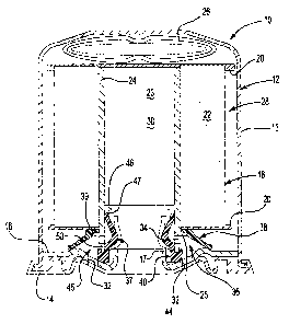
Figure 1 is a cross-sectional view of a fluid filter with an example of the
inventive valve assembly with separate relief and anti-drain back valves.
Figure 2 is an enlarged cross-sectional view of the anti-drain back valve
shown in Figure 1.
Figure 3 is an enlarged cross-sectional view of the relief valve shown in
Figure 1.
DETAILED DESCRIPTION OF THE PREFERRED EMBODIMENT
A fluid filter 10 is shown in Figure 1. The filter 10 shown is suitable for
use
as a vehicle oil filter, however, this invention may be used in any fluid
filter
application. The filter 10 comprises a housing 12 including a can 13 with a
retainer
14 secured to the open end of the can. The housing 12 also includes a tapping
plate
16 typically arranged interiorly and adjacent to the retainer 14. The tapping
plate 16
includes a central threaded hole 17 for securing the filter 10 to a structure
having
fluid passages that carry the fluid to and from a desired location such as a
vehicle
engine.
A filter assembly 18 is arranged within the housing 12. The filter assembly
18 includes end discs 20 having a filter media 22, such as a paper filter
element,
arranged between the end discs 20 in any suitable manner, which is well known
in
the art. The filter media 22 may define a central opening 23. Typically, the
filter
media 22 is a pleated paper element having a center tube 24 inserted into a
central
opening 23 of the filter media 22 to provide structural support for the
pleated paper
element. The center tube 24 has openings to permit fluid flow through the
center
tube 24. The center tube 24 has a collar 25 for axially locating the center
tube 24
relative to the filter assembly 18. A guide 26 is arranged between the filter
assembly
18 and the housing 12 to position the filter assembly 18 in a desired manner
during
assembly of the filter 10.
-3-
CA 02490314 2004-12-15
The filter 10 has an inlet side 28 on one side of the filter media 22 and an
outlet side 30 on the opposite side of the filter media 22. For the
arrangement
shown, the inlet side 28 corresponds to the outside of the filter assembly 18,
and the
outlet side 30 corresponds to the inside or central opening 23. The retainer
14 and
tapping plate 16 include apertures 32 to permit fluid to flow from the
structure
supporting the filter 10 to the inlet side 28. During normal operation, the
fluid flows
through the filter media 22 to the central opening 23, which corresponds to
the outlet
side 30, to remove debris from the fluid. Fluid then flows through the central
opening 23 and exits through the threaded hole 1? back through the structure
supporting the filter 10. However, it is to be understood that the fluid flow
may be
other than described above depending upon the application and customer
specifications.
It is desirable to incorporate valves within the filter to prevent fluid from
draining from the dirty or inlet side 28 of the filter 10 back to the
structure
supporting the filter 10 during engine shut down. It is also desirable to
provide
valves within the filter 10 to permit fluid to bypass the filter assembly 18
during high
differential pressure conditions, such as vehicle cold starts at very low
temperatures
in which the fluid may be very viscous and when the filter assembly 18 is
plugged
with debris. In the prior art, these valves have been separate and have
included
many components, in particular with respect to the relief valve.
The inventive valve assembly 36 comprises a separate two-piece anti-drain
back valve 38 and relief valve 40. As best shown in Figure 2, the anti-drain
back
valve 38 includes a first annular lip 41 ending to a first terminal end 42.
Similarly,
the relief valve 40 includes a second annular lip 43 ending to a second
terminal end
44, best shown in Figure 3. The terminal ends 42, 44 include enlarged portions
that
better enable the lips 41, 43 to seal against their respective sealing
surfaces. A hole
defined by circumference at 37 in the relief valve 40 permits fluid flow
through the
filter 10.
Returning to Figure 1, the anti-drain back valve 38 is arranged adjacent to
the
aperture 32 in the retainer 14 and tapping plate 16. An inner portion 39 of
the anti
drain back valve 38 is captured between the end disc 20 and collar 25. The
valves
-4-
CA 02490314 2004-12-15
38 and 40 together form a cavity 45 in which the fluid must enter prior to
deflecting
one of the valves 38 and 40 and flowing through the filter. The anti-drain
back valve
is deflected upward due to positive flow pressures to permit fluid flow into
the inlet
side 28 of the filter 10. The terminal end 42 of the anti-drain back valve 38
seals
against a raised portion of the tapping plate 16 to prevent fluid on the inlet
side 28
from carrying debris and oil from the filter media 22 out of the filter 10
during
engine shut down. The center tube 24 includes an opening 34. The relief valve
40 is
arranged within the center tube 24 in a generally longitudinal orientation and
adjacent to the opening 34 for preventing fluid from bypassing the filter
assembly 18
during normal operation. However, during conditions in which the fluid is very
viscous such as during vehicle cold starts at low temperatures, or when filter
assembly 18 becomes plugged with debris it may be desirable to bypass the
filter
assembly 18 in which case the terminal end 44 is forced out of engagement with
the
inner surface 47 due to high differential pressures.
The relief valve 40 is captured between the center tube 24 and the tapping
plate 16. The relief valve 40 includes an annular recess 48 with an end 50 of
the
center tube 24 received in the recess 48. The relief valve 40 in the area of
the recess
48 forms a U-shaped portion forming a seal between the center tube 24 and
tapping
plate 16 preventing fluid from bypassing the filter assembly 18. In this
manner, the
relief valve 40 eliminates the separate seal typically used between the center
tube 24
and tapping plate 16.
The valve assembly 36 may be an elastomeric material such as a rubber. The
pressures at which the valves 38 and 40 may be opened may be modified by using
rubbers of different durometers or varying the thicknesses in desired areas of
the
valves 38 and 40 to change the opening characteristics of the valves 38 and
40.
Since the valves 38 and 40 are separate from one another, different materials
may be
used. For example, the valves 38 and 40 respectively include "knees" 52, 54
that act
as fulcrums. The locations, geometry, and thickness of the knees 52, 54 may be
varied to change the opening characteristics.
The two-piece valve assembly 36 also simplifies assembly as compared to
prior art arrangements. The anti-drain back valve 38 is inserted onto the
center tube
-5-
CA 02490314 2004-12-15
24, and the center tube 24 is inserted into the filter assembly 18 until the
valve 38
abuts the end disc 20 and collar 25. The end disc 20 is movable relative to
the collar
25 so that the inner portion 39 may be compressed during assembly to more
securely
retain the valve 38. The relief valve 40 is installed onto the end 50 so that
the end 50
is received in the annular recess 48. The filter assembly 18 and valves 38 and
40 are
installed into the can 13 and the tapping plate 16 and retainer 14 are
assembled onto
the can 13 so that the valves 38 and 40 seal against the tapping plate 16.
The invention has been described in an illustrative manner, and it is to be
understood that the terminology that has been used is intended to be in the
nature of
words of description rather than of limitation. Obviously, many modifications
and
variations of the present invention are possible in light of the above
teachings. It is,
therefore, to be understood that within the scope of the appended claims the
invention may be practiced otherwise than as specifically described.
-6-