Note : Les descriptions sont présentées dans la langue officielle dans laquelle elles ont été soumises.
~
CA 02496370 2005-02-07
ULTRASONIC FLAW DETECTING METHOD AND
ULTRASONIC FLAW DETECTOR
BACKGROUND OF THE INVENTION
The present invention relates to an
ultrasonic flaw detection technique for inspecting a
solid body, and in particular, to an ultrasonic flaw
detection technique for carrying out ultrasonic flaw
detection by a phased array technique by use of an
array sensor.
As a nondestructive inspection technique for
a solid body allowing propagation of both longitudinal
waves and shear waves (e. g. steel), a technique using
ultrasonic waves (ultrasonic flaw detection) has been
generally used. As a type of the ultrasonic flaw
detection, there exists flaw detection using the so-
called phased array technique.
Here, the phased array technique is also
called an "electronic scan technique", in which a probe
including a plurality of ultrasonic generator elements
(made of piezoelectric elements) arranged in an array
(the so-called "array probe") is used. In the
technique, electric signals as triggers for the
generation of ultrasonic waves are successively
supplied to the elements of the array probe at
prescribed time intervals (delays) and the ultrasonic
waves generated by the elements are superposed on one
another to form a superposed wave, by which various
CA 02496370 2005-02-07
1.
- 2 -
conditions such as the transmission/reception
angle/position of ultrasonic waves to/from the specimen
being inspected, positions having enhanced energy due
to the interference in the superposed wave (i.e. focal
positions), etc. can be changed at high speed by means
of electronic control.
The array probe is used for electrically
scanning the flaw detection conditions since the
transmission/reception angle/position and the focal
positions of ultrasonic waves can be changed freely
across a wide inspection range, by which an angle,
position and focal points allowing reception of
stronger reflected waves (echoes) from a reflector
(defect, etc.) existing inside or on a surface of the
specimen can be selected and thereby defects as
reflectors can be found easily.
On the other hand, in a widely employed
ultrasonic flaw detection technique using only one
ultrasonic probe (two probes (transmission/reception
probes) when separate probes are used for transmission
and reception respectively), one probe can realize only
one probe condition (transmission/reception angle,
transmission/reception position, focal position), and
thus a plurality of probes have to be prepared in order
to achieve different flaw detection conditions.
Even the aforementioned phased array
technique using an array probe is being adopted, in
most cases, for the purpose of expanding the functions
CA 02496370 2005-02-07
- 3 -
of conventional probes. Therefore, even when the
integrity of a specimen is evaluated by use of the
phased array technique, the so-called angled flaw
detection technique (evaluating the integrity by
letting shear waves or longitudinal waves propagate in
the specimen in an oblique direction and receiving
waves reflected by a reflector such as a defect) is
mainly used, similarly to the case of flaw detection
using a conventional probe.
The angled flaw detection technique can be
characterized as having a common and fixed propagation
mode (longitudinal or shear) of the wave transmitted,
the wave propagating in the specimen and the wave
received. For example, in an angled longitudinal wave
flaw detection technique, a longitudinal wave
transmitted is reflected by a reflector (defect, etc.)
and the reflected wave is received by the probe also as
a longitudinal wave.
Meanwhile, as a flaw detection technique
using a fixed angle besides the angled flaw detection
technique, there exist an ID creeping technique for
judging whether there exists a reflector such as a
defect and a mode conversion technique capable of
roughly evaluating the dimensions of a defect.
These techniques can contribute to the
improvement of reliability of the angled longitudinal
wave technique. For example, when a defect existing in
an inspection area of the specimen is searched for by
CA 02496370 2005-02-07
- 4 -
use of an angled beam, there are cases where an echo
(reflected wave) from a deformed part of the specimen
(e.g. deformation caused by welding or machining) is
received. In such cases, the discrimination between an
echo caused by such a deformed part and an echo from a
defect can be very difficult.
In such cases, if the aforementioned ID
creeping waves or mode conversion waves are used
together with the angled longitudinal waves (angled
beam), discriminability of echoes can be increased and
that contributes to the improvement of reliability of
flaw detection results obtained by the angled flaw
detection technique.
By the way, in the ID creeping waves and the
mode conversion waves used in the aforementioned
techniques, the wave transmitted, the wave propagating
in the specimen and the wave received do not have the
same propagation mode, differently from the case of the
angled flaw detection technique. For example, in the
ID creeping technique, shear ultrasonic waves (angle:
approximately 30°), generated simultaneously with
longitudinal waves (angle: approximately 70°) by a
longitudinal wave probe, are used, and the propagation
mode changes later as will be explained below.
Here, a brief outline of the propagation of
ultrasonic waves in the ID creeping technique will be
explained referring to Fig. 4. When a shear wave 401
is emitted from an ultrasonic transducer, the
CA 02496370 2005-02-07
- 5 -
propagation mode of the wave changes from the shear
wave to a longitudinal wave 402 (mode conversion) when
the wave is reflected by a far surface (base) of the
specimen. Thereafter, the longitudinal wave 402 is
reflected by a crack corner of a crack (defect) 403.
The crack corner of the crack is a portion near a
surface of the specimen.
A longitudinal wave 404 (the longitudinal
wave 402 after being reflected by the crack corner)
propagates in the vicinity of the far surface of the
specimen. During the propagation along the far
surface, the longitudinal wave 404 converts into a
shear wave 405 (mode conversion), by which the shear
wave 405 returns to the ultrasonic transducer and is
received as an echo from the crack corner.
As above, the ID creeping technique, enabling
the reception of echoes from crack corners, is
effective fox judging whether a specimen has a defect
or not.
In the so-called mode conversion technique
using the mode conversion of ultrasonic waves as above,
shear ultrasonic waves (angle: approximately 28°)
generated simultaneously with longitudinal waves
(angle: approximately 60°) by a longitudinal ultrasonic
transducer are used.
Thus, a brief outline of the propagation of
ultrasonic waves in the so-called mode conversion
technique will be explained below referring to Figs. 5A
CA 02496370 2005-02-07
- 6 -
and 5B. The propagation mode of a shear wave 501
generated by an ultrasonic transducer changes from the
shear wave to a longitudinal wave 502 when the wave is
reflected by the far surface of the specimen.
In cases where a reflector 502 shown in Fig.
5A is a defect having a certain height, reflection
occurs at the tip of the defect or on the surface of
the defect on the way to the tip. A longitudinal wave
504 reflected by the defect returns directly to the
ultrasonic transducer through the specimen and is
received as an echo from the defect.
However, in the case of a reflector 507 shown
in Fig. 5B which is relatively low, a longitudinal wave
506 (generated by the mode conversion from a shear wave
505 at the far surface of the specimen) can not meet
the tip of the defect, by which there appears no
ultrasonic wave returning to the ultrasonic transducer.
As above, in the mode conversion technique, whether the
defect has a certain height (approximately ll3 of the
wall thickness of the specimen) or not corresponds to
the presence/absence of an echo from the defect. Thus,
the mode conversion technique is effective for roughly
determining the height of a detect.
However, since the two techniques explained
above employ a judgment based on a waveform called "A-
scan" (plotted on a graph with the vertical axis
representing reception intensity of ultrasonic waves
and the horizontal axis representing propagation
CA 02496370 2005-02-07
distance or propagation time inside the specimen), it
is extremely difficult and requires skill to clarify
the origin of the complex propagation path inside the
specimen shown in Figs. 4, 5A and 5B and determine the
presence/absence of a defect or the approximate size of
the defect.
Meanwhile, in order to implement the
aforementioned ID creeping technique or the mode
conversion technique by use of an array probe, the
array probe is required to generate both longitudinal
waves and shear waves in intended directions.
However, with conventional array probes, the
generation of longitudinal and shear waves in intended
directions is generally accompanied by ultrasonic waves
being radiated in other directions, by which the
identification of propagation paths of received
ultrasonic waves and the implementation of the above
techniques by use of an array probe become difficult.
In the conventional phased array technique,
two types of probes: an array probe making direct
contact with the specimen for generating longitudinal
waves (the so-called "array probe in contact
technique") and an array probe supporting both
longitudinal waves and shear waves using a wedge-shaped
intermediate medium called "wedge" or "shoe" (the so-
called "array probe with a wedge") have been used
mainly. Therefore, features and problems with each of
the array probes will be explained below.
,, CA 02496370 2005-02-07
-
The array probe in contact technique is an
array probe for longitudinal waves, placed to directly
contact the specimen or to be in parallel with the
specimen. In the array probe, ultrasonic transducer
elements such as piezoelectric elements are arranged in
a line (array) and the angle of transmission/reception
of ultrasonic waves propagating in the specimen is
electronically changed from vertical (angle; 0°) to 45°
(or 60°) .
In this case, longitudinal waves including
components perpendicular to the specimen are generated
by each ultrasonic transducer element of the array
probe. Therefore, longitudinal waves propagating in an
intended angle 8 can be synthesized by giving a proper
delay time determined by the following expression (1)
to each element (see "Handbook of Ultrasonic Diagnostic
Equipment (Revised Edition)", pp.39-40, Electronic
Industries Association of Japan (1997), for example):
Ti = (i - 1) P ~ sin6/c . . . (1)
where "i" denotes a serial number of each element, "ti"
denotes a delay time given to the i-th element, "c"
denotes wave velocity (propagation speed) of
longitudinal waves in the specimen (solid body), "P"
denotes the element pitch, and "8" denotes the incident
angle (incident direction) of the ultrasonic waves.
It is well known that ultrasonic waves
CA 02496370 2005-02-07
_ g _
propagating in other directions ~ are also synthesized
in addition to the ultrasonic waves (main beam)
propagating in the intended direction 8.
For preventing the synthesis of the undesired
ultrasonic waves (hereinafter referred to as "grating
lobes") other than the main beam propagating in the
intended direction (angle) A, the element pitch P in the
expression (1) has to be set smaller than or equal to a
value determined by the following expression (2):
P = ~/(1 + ~sinA~) ...(2)
where "~" denotes the wavelength of longitudinal waves
in the specimen (solid body).
Since the maximum value of the incident angle
B of the ultrasonic waves is 90°, the minimum value of
the element gap in the expression (2) is 1/2 of the
wavelength.
While the array probe in contact technique is
capable of transmitting longitudinal waves in a wide
range of angles without causing the grating lobes, a
grating occurs to shear waves at the same time,
hampering the implementation of the aforementioned ID
creeping technique or mode conversion technique by use
of the array probe.
There have been proposed a method and a
device implementing an angled shear wave flaw detection
technique by use of an array probe by focusing
CA 02496370 2005-02-07
. ''
- 10 -
attention on shear waves simultaneously generated by
the piezoelectric elements of the array probe, treating
longitudinal waves generated simultaneously with the
shear waves as noise, and reducing the noise (see JP-A-
2001-255308, for example).
However, even the above proposition discloses
nothing about an ID creeping technique or mode
conversion technique that utilizes both longitudinal
waves and shear waves simultaneously generated by the
array probe.
Meanwhile, the array probe with a wedge is an
array probe including an array sensor placed with a
tilt angle relative to the specimen and an extra medium
sandwiched between the array sensor and the specimen.
Typical examples of the medium placed between the array
sensor and the specimen include water and synthetic
resin (acrylic, polystyrene, polyimide, etc.). The
intermediate medium is called a "wedge" or "shoe" as
mentioned above.
By use of the wedge, even when the incident
angle of the ultrasonic waves upon the wedge is small,
a large refractive angle for the incidence upon the
specimen can be achieved thanks to the refraction of
the ultrasonic waves (see "Ultrasonic Testing (Revised
Edition)", pp.35-47 and 746, The 19th Committee on
Steelmaking, Japan Society for the Promotion of Science
(1974), for example).
The following equation (3) represents the
CA 02496370 2005-02-07
s
- 11 -
relationship between the incident angle B' upon the
wedge and the refractive angle 8 into the specimen:
8' - sin-lA(sin8 x V'/V) ...(3)
where "A "' denotes the incident angle of the
longitudinal waves upon the wedge, "8" denotes the
refractive angle of the ultrasonic waves incident upon
the specimen, "V "' denotes wave velocity of
longitudinal waves in the wedge, and "V" denotes wave
velocity of longitudinal waves in the specimen (solid
body).
For example, when ultrasonic waves are
incident upon steel (iron) (wave velocity:
approximately 5900 m/s (longitudinal wave),
approximately 3000 m/s (shear wave)) from water (wave
velocity: approximately 1500 m/s), shear waves incident
upon the specimen at an incident angle of 70° can be
achieved by letting the ultrasonic waves incident upon
the water at an incident angle of approximately 14°.
However, shear waves at an angle of approximately 29°
develop in the steel at the same time.
By this, multiple reflection echoes inside
the wedge axe received by the probe as noise signals,
which can hamper the identification of echoes from
defects.
SUMMARY OF THE INVENTION
CA 02496370 2005-02-07
- 12 -
As described above, the aforementioned
conventional techniques, having paid no attention to
the generation of ultrasonic waves containing the main
beam only and including no grating lobes (ultrasonic
waves propagating in directions other than the intended
direction) by use of an array probe, have difficulties
in the implementation of the ID creeping technique and
the mode conversion technique.
Further, the above conventional techniques
have not focused on the identification of echoes
(reflected waves) from defects and it has been
difficult to clearly identify ID creeping waves or mode
conversion waves by use of images.
It is therefore the primary object of the
present invention to provide an ultrasonic flaw
detection method and an ultrasonic flaw detector
capable of generating ultrasonic waves containing the
main beam only and including no grating lobes
(ultrasonic waves propagating in directions other than
the intended direction) in regard to both longitudinal
waves and shear waves even when an array probe is used.
Another object of the present invention is to
provide an ultrasonic flaw detection method and an
ultrasonic flaw detector capable of realizing clear
identification of defect echoes deriving from ID
creeping waves or mode conversion waves propagating in
the specimen through complex paths, by use of images.
In the present invention, a wall of tube is also
CA 02496370 2005-02-07
- 13 -
included in the specimen.
In order to achieve the above objects, in
ultrasonic flaw detection according to the phased array
technique using an array probe including an array of
transducer elements, the distance between centers of
adjacent transducer elements in the array probe is set
longer than 1/4 of the wavelength of longitudinal waves
in a specimen as the object of flaw detection and
shorter than 1/2 of the wavelength.
Preferably, reception signals obtained by the
array probe are displayed for a period covering at
least a time corresponding to the sum of round-trip
propagation time for longitudinal waves in a wall
thickness direction of the specimen and round-trip
propagation time for shear waves in the wall thickness
direction.
The integrity of the specimen may be
evaluated based on the presence/absence of a signal
displayed after time corresponding to twice the round-
trip propagation time for longitudinal waves in the
wall thickness direction and by time corresponding to
the sum of the round-trip propagation time for
longitudinal waves in the wall thickness direction and
the round-trip propagation time for shear waves in the
wall thickness direction. The integrity of the
specimen may also evaluated based on the
presence/absence of a signal displayed after time
corresponding to the sum of one-way propagation time
CA 02496370 2005-02-07
- 14 -
for longitudinal waves in the wall thickness direction
of the specimen (100) and one-way propagation time for
shear waves in the wall thickness direction and by time
corresponding to the sum of three times the one-way
propagation time for longitudinal waves in the wall
thickness direction and the one-way propagation time
for shear waves in the wall thickness direction.
By use of an array probe in which the
distance between centers of adjacent transducer
elements is set between 1/4 wavelength and 1/2
wavelength of longitudinal waves generated by the
transducer elements as above, ultrasonic waves
containing the main beam only and including no grating
lobes (ultrasonic waves propagating in directions other
than the intended direction) can be generated in regard
to both longitudinal waves and shear waves even by use
of an array probe.
In this case, the reception signals up to the
time corresponding to the sum of the wall thickness
round-trip propagation time for longitudinal waves and
the wall thickness round-trip propagation time for
shear waves in the specimen are displayed, and based on
the presence/absence of a signal displayed after time
corresponding to twice the wall thickness round-trip
propagation time for longitudinal waves and by time
corresponding to the sum of the wall thickness round-
trip propagation time for longitudinal waves and the
wall thickness round-trip propagation time for shear
CA 02496370 2005-02-07
- 15 -
waves, the presence/absence of an echo from a defect
deriving from the ID creeping waves can be judged and
whether the specimen has a defect or not can be judged
based on images.
Further, based on the presence/absence of a
signal displayed after time corresponding to the sum of
the wall thickness one-way propagation time for
longitudinal waves and the wall thickness one-way
propagation time for shear waves and by time
corresponding to twice the wall thickness round-trip
propagation time for longitudinal waves, the
presence/absence of an echo from a defect deriving from
the mode conversion waves can be judged and the
approximate height of the defect can be evaluated based
on images.
By the present invention, in a specimen
including a solid body allowing propagation of both
longitudinal waves and shear waves, ultrasonic waves
containing the main beam only and including no grating
lobes (ultrasonic waves propagating in directions other
than the intended direction) can be generated in regard
to both longitudinal waves and shear waves by use of an
array probe.
Further, also regarding ID creeping waves and
mode conversion waves having complex propagation paths,
the presence/absence of signals displayed in particular
areas specified by particular propagation times is
judged, by which defect echoes deriving from the ID
CA 02496370 2005-02-07
- 16 -
creeping waves and mode conversion waves can be
identified clearly based on images. By this, the
presence/absence of a defect in the specimen can be
judged reliably and the approximate height of the
defect can be evaluated.
BRIEF DESCRIPTION OF THE DRAWINGS
The objects and features of the present
invention will become more apparent from the
consideration of the following detailed description
taken in conjunction with the accompanying drawings, in
which:
Fig. 1 is a schematic diagram for explaining
an ultrasonic flaw detection method and an ultrasonic
flaw detector in accordance with a first embodiment of
the present invention;
Fig. 2 is a schematic diagram showing an
example of the composition of an array probe
(ultrasonic transducer) employed in the first
embodiment of the present invention;
Figs. 3A - 3C are graphs for explaining a
main beam and a grating lobe of longitudinal/shear
waves generated by the ultrasonic transducer;
Fig. 4 is a schematic diagram for explaining
an ID creeping technique;
Figs. 5A and 5B are schematic diagrams for
explaining a mode conversion. technique;
Fig. 6 is a table for explaining
CA 02496370 2005-02-07
- 17 -
longitudinal/shear wave velocities and wave velocity
ratios in various solid bodies;
Fig. 7 is a schematic diagram for explaining
an angled flaw detection technique;
Figs. 8A - 8F are schematic diagrams showing
multiple reflection bottom echoes in a specimen and a
display image;
Fig. 9A is a schematic diagram showing a
display method employed in the first embodiment of the
present invention;
Fig. 9B is a flow chart showing a display
method employed in the first embodiment of the present
invention;
Fig. 10 is a graph explaining propagation
times of echoes caused by ID creeping waves employed in
the first embodiment of the present invention;
Fig. 11 is a graph explaining propagation
times of echoes caused by ID creeping waves employed in
the first embodiment of the present invention;
Fig. 12 is a graph explaining propagation
times of echoes caused by ID creeping waves employed in
the first embodiment of the present invention;
Fig. 13 is a graph explaining propagation
times of echoes caused by mode conversion waves
employed in the first embodiment of the present
invention:
Fig. 14 is a graph explaining propagation
times of echoes caused by mode conversion waves
CA 02496370 2005-02-07
- 18 -
employed in the first embodiment of the present
invention;
Fig. 15 is a graph explaining propagation
times of echoes caused by mode conversion waves
employed in the first embodiment of the present
invention;
Figs. 16A - 16C are graphs showing defect
heights allowing the reception of mode conversion waves
in the first embodiment of the present invention;
Fig. 17 is a schematic diagram explaining
angled longitudinal wave flaw detection in search of a
defect open to a near surface of the specimen;
Fig. 18 is a schematic diagram explaining
angled longitudinal wave flaw detection in search of a
defect open to the near surface of the specimen;
Figs. 19A and 19B are schematic diagram
explaining flaw detection by use of mode conversion
waves in a second embodiment of the present invention;
Fig. 20A is a schematic diagram showing a
display method employed in the second embodiment of the
present invention;
Fig. 20B is a flow chart showing a display
method employed in the second embodiment of the present
invention;
Fig. 21 is a graph explaining propagation
times of echoes caused by mode conversion waves
employed in the second embodiment of the present
invention;
CA 02496370 2005-02-07
- 19 -
Fig. 22 is a graph explaining propagation
times of echoes caused by mode conversion waves
employed in the second embodiment of the present
invention;
Fig. 23 is a graph explaining propagation
times of echoes caused by mode conversion waves
employed in the second embodiment of the present
invention;
Figs. 29A - 24C are graphs showing defect
heights allowing the reception of mode conversion waves
in the second embodiment of the present invention;
Fig. 25 is a schematic diagram showing an
example of a flaw detection display screen when echoes
caused by angled longitudinal waves are displayed in
the first embodiment of the present invention;
Fig. 26 is a schematic diagram showing an
example of a flaw detection display screen when echoes
caused by angled longitudinal waves and ID creeping
waves are displayed in the first embodiment of the
present invention:
Fig. 27 is a schematic diagram showing an
example of a flaw detection display screen when echoes
caused by angled longitudinal waves, ID creeping waves
and mode conversion waves are displayed in the first
embodiment of the present invention;
Fig. 28 is a schematic diagram showing an
example of a flaw detection display screen when an echo
from a part of the specimen in the vicinity of a crack
CA 02496370 2005-02-07
1
corner caused by angled longitudinal waves is displayed
in the second embodiment of the present invention;
Fig. 29 is a schematic diagram showing an
example of a flaw detection display screen when echoes
from parts of the specimen in the vicinity of a crack
corner and a crack tip caused by angled longitudinal
waves are displayed in the second embodiment of the
present invention:
Fig. 30 is a schematic diagram showing an
example of a flaw detection display screen when echoes
from parts of the specimen in the vicinity of a crack
corner and a crack tip caused by angled longitudinal
waves and echoes caused by mode conversion waves are
displayed in the second embodiment of the present
invention;
Fig. 31 is a schematic diagram explaining
measurement of the height of a defect (crack) based on
echoes from a tip and corner of the crack caused by
angled longitudinal waves in the first embodiment of
the present invention;
Fig. 32 is a schematic diagram showing an
example of a flaw detection screen when an element
pitch of the array probe is too large;
Fig. 33 is a schematic diagram explaining
echoes occurring when there is a defect at a far
surface of the specimen in the first embodiment of the
present invention: and
Fig. 34 is a schematic diagram explaining
CA 02496370 2005-02-07
- 21 -
echoes occurring when there is a deformed part at the
far surface of the specimen in the first embodiment of
the present invention.
DESCRIPTION OF THE EMBODIMENTS
Referring now to the drawings, a description
will be given in detail of embodiments in accordance
with the present invention. In each drawing, the
specimen illustrated by a box also represents a
sectional plane in an axial direction of a tube shaped
specimen as well as that of plate shaped specimen.
[Embodiment 1]
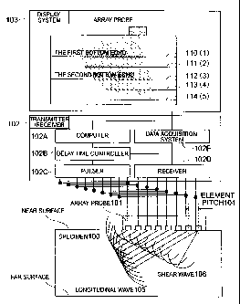
Fig. 1 is a schematic diagram for explaining
an ultrasonic flaw detection method and an ultrasonic
flaw detector in accordance with a first embodiment of
the present invention. The embodiment shown in Fig. 1
includes a specimen 100 as the object of inspection, an
array probe 101 which emits ultrasonic waves into the
specimen 100, a transmitter/receiver 102, and a display
system 103 which displays received signals.
Incidentally, in the first embodiment, an example of
flaw detection in search of a defect (crack) open to
the far surface of the specimen 100 will be explained.
The array probe 101 is set on a flaw
detection surface (near surface) of the specimen 100 to
generate ultrasonic waves in response to a driving
signal supplied from the transmitter/receiver 102. The
ultrasonic waves emitted by the array probe 101
CA 02496370 2005-02-07
- 22 -
propagates through the specimen 100, and reflected
waves are detected by the array probe 101. A reception
signal generated by the array probe 101 according to
the detection of the reflected waves (echoes) is
inputted to the transmitter/receiver 102.
The transmitter/receiver 102 includes a
computer 102A, a delay time controller 102B, a pulser
102C, a receiver 102D and a data acquisition system
102E. The driving signal is supplied from the pulser
102C to the array probe 101, while the reception signal
outputted by the array probe 101 accordingly is
processed by the receiver 102D.
The computer 102A controls the delay time
controller 1028, the pulser 102C, the receiver 102D and
the data acquisition system 102E so that the components
will operate properly.
The delay time controller 102B controls the
timing of the driving signal outputted by the pulser
102C while controlling input timing of the reception
signal by the receiver 102D so as to achieve the
operation of the array probe 101 according to the
phased array technique.
The data acquisition system 102E processes
the reception signal supplied from the receiver 102D
and supplies the result of the processing to the
display system 103. The operation of the display
system 103 will be described in detail later.
Next, the details of the array probe 101 will
CA 02496370 2005-02-07
- 23 -
be explained referring to Fig. 2. Fig. 2 is a
schematic diagram showing the most basic composition of
the array probe 101. As shown in Fig. 2, the array
probe 101 is basically composed of a plurality of
ultrasonic transducer elements 201.
In this embodiment, a composite piezoelectric
body (also called a "composite") including a thin bar
of PZT piezoelectric ceramic embedded in a polymeric
material is used as an example of the ultrasonic
transducer element 201. In this case, parameters
determining the performance of the array probe 101
include an element pitch P.
The element pitch P is a length obtained by
adding an element width W of the ultrasonic transducer
element 201 to a gap G between the elements. The
element pitch P is one of the major factors determining
the generation of the main beam and grating lobes by
the array probe 101.
As explained in the description of background
arts, the conventional techniques have aimed at the
generation of longitudinal waves and thus ultrasonic
transducer elements for generating the longitudinal
waves have been designed focusing mainly on the
longitudinal waves which are formed by the
superposition of ultrasonic waves generated by the
elements. Therefore, in order to prevent the
generation of grating lobes (ultrasonic waves
propagating in directions other than the intended
CA 02496370 2005-02-07
- 24 -
incident direction) regarding the longitudinal waves,
the element pitch has generally been set to 1/2 of the
wavelength.
Here, effects of the element pitch will be
explained referring to Figs. 3A, 3B and 3C. First,
calculations for an array probe including 24 elements
generating ultrasonic waves including longitudinal
waves propagating in an angle of 60° in steel will be
shown.
Fig. 3A shows the main beam and grating lobes
obtained by setting the element pitch to 1/2 of the
wavelength as in the conventional array probes. Fig.
3B shows a case where the element pitch is reduced to
1/4 of the wavelength. Fig. 3C shows a case where an
element pitch proposed by the present invention (1/3 of
the wavelength) is employed.
As seen in the figures, the conventional
element pitch (1/2 wavelength) and the element pitch of
the present invention (1/3 wavelength) both cause a
main beam (longitudinal waves) in the intended
direction 60° and there is no problem about this point:
However, if we focus attention on shear waves
generated simultaneously with the longitudinal waves,
although the shear waves should include only a main
beam propagating in a direction of approximately 29°,
other shear waves (grating lobe) developing in
approximately - 40° is seen in Fig. 3A employing the
conventional element pitch.
CA 02496370 2005-02-07
- 25 -
Meanwhile, in the case of Fig. 3C employing
the element pitch of the present invention (1/3
wavelength), even the shear waves generated by the
array probe include the main beam only, showing that
the element pitch of the present invention also
satisfies the condition regarding the shear waves.
The case of Fig. 3B where the element pitch
is further reduced from 1/3 wavelength seems to have no
particular problem since no grating lobe develops both
in the longitudinal waves and shear waves. However, if
we pay attention to the longitudinal waves, the half
value width of the main beam propagating in the
direction of 60° (hereinafter referred to as a
"directivity angle") in Fig. 3B has become wider
(approximately 20°) than that in Fig. 3C. By the
broadening of the directivity angle, the identification
of the directions of received signals (echoes from
reflectors) becomes difficult.
Thus, in order to implement the ID creeping
technique or mode conversion technique generating both
longitudinal ultrasonic waves and shear ultrasonic
waves by use of an array probe, it is necessary to
generate the main beam only in regard to both the
longitudinal waves and the shear waves while keeping
the directivity angle within a certain range so that
the directions of echoes received from the reflectors
can be identified.
For the above reasons, the present invention
CA 02496370 2005-02-07
- 26 -
employs a condition causing no grating lobe inside a
shear wave angle range (shear wave critical angle) when
the longitudinal waves propagate in the 90-degree
direction (see equation (4)) as a standard for
determining the element pitch.
d n+(vivs~ .. . (~)
where "~," denotes the wavelength of
longitudinal waves in the specimen, "V" denotes the
wave velocity of longitudinal waves in the specimen and
"Vs" denotes the wave velocity of shear waves in the
specimen.
The ratio between longitudinal wave velocity
V and shear wave velocity Vs in a solid body (V/Vs:
wave velocity ratio) takes on values around 2 in many
solid bodies as shown in Fig. 6 (see "Ultrasonic
Testing (Revised Edition)," The 19th Committee on
Steelmaking, Japan Society for the Promotion of Science
(1974)).
Therefore, by generalizing the result of the
equation (4), the present invention regards the optimum
element pitch to be around 1/3 wavelength of the
longitudinal waves (from 1/4 wavelength to 1/2
wavelength).
For example, when the longitudinal wave
velocity in the specimen is 6000 m/s and the frequency
of the ultrasonic waves used in this case is 2 MHz, an
CA 02496370 2005-02-07
- 27 -
element pitch 1.0 mm (1/3 wavelength) may be selected
as the optimum element pitch in the embodiment of the
present invention.
In this case, by adopting an element width W
- 0.9 mm and a gap G = 0.1 mm, for example,
longitudinal ultrasonic waves and shear ultrasonic
waves with no grating lobes can be transmitted and
received.
Next, a method for displaying the flaw
detection results in accordance with an embodiment of
the present invention will be described below. The ID
creeping waves and the mode conversion waves are
characterized by shear waves which propagate in the
specimen at lower wave velocity than longitudinal
waves.
Thus, the ID creeping waves and the mode
conversion waves need more propagation time until the
reflected waves are received by the probe, in
comparison with the ordinary angled longitudinal wave
flaw detection technique which deals with the
propagation of longitudinal waves only.
Fig. 7 shows a brief outline of the
propagation path of longitudinal waves in a 45-degree
angled longitudinal wave technique (transmitting and
receiving longitudinal waves at an angle of 45°) which
is widely employed in the angled longitudinal wave
technique. In this case, a longitudinal wave 701
transmitted by the ultrasonic transducer reaches a
CA 02496370 2005-02-07
- 28 -
reflector 702, gets reflected by the corner or the tip
of the reflector, returns to the ultrasonic transducer
as a longitudinal wave 703, and is received by the
ultrasonic transducer as a signal.
Compared with the 45-degree angled
longitudinal wave technique shown in Fig. 7, the
propagation path in the ID creeping technique or the
mode conversion technique of the present invention is
more complex and longer as explained referring to Figs.
4, 5A and 5B. Therefore, in order to display the
reflected waves (echoes) properly, it is necessary to
keep on displaying the echoes during a proper time
period corresponding to a certain propagation time.
Therefore, in this embodiment, time lengths
regarding multiple bottom echoes developing in the
specimen are used as standards for determining the
propagation time for the waveform display. Figs. 8A -
8F are schematic diagrams showing examples of
visualization of multiple bottom echoes in a tabular
specimen by use of a phased array technique
(electronically scanning the incident angle of
ultrasonic waves) and propagation paths in the multiple
reflections.
With an array probe set on a near surface of
the specimen, multiple reflection is caused between the
near surface and far surface of the specimen. Figs. 8A
- 8E summarize types of echoes included in the multiple
reflection in ascending order of propagation time.
CA 02496370 2005-02-07
- 29 -
Multiple bottom echoes deriving from the five events
are actually received by the array probe as shown in
Fig. SF which represents an example of a resultant
image of the flaw detection by use of the array probe
(see black parts in ellipses (1) - (5) in Fig. SF).
Figs. 8A - 8E correspond to (1) - (5), respectively.
Therefore, in the embodiment of the present
invention, identifiability of the ID creeping waves and
mode conversion waves is increased by considering the
following five time lengths.
i. time of a first bottom echo corresponding to
wall thickness round-trip propagation time for
longitudinal waves (Fig. 8A)
ii. time corresponding to the sum of wall
thickness one-way propagation time for longitudinal
waves and wall thickness one-way propagation time for
shear waves (Fig. 8B)
iii. time of a second bottom echo corresponding
to twice the wall thickness round-trip propagation time
for longitudinal waves (Fig. 8C)
iv. time corresponding to the sum of three times
the wall thickness one-way propagation time for
longitudinal waves and the wall thickness one-way
propagation time for shear waves (Fig. 8D)
v. time corresponding to the sum of wall
thickness round-trip propagation time for longitudinal
waves and wall thickness round-trip propagation time
for shear waves (Fig. 8E)
t CA 02496370 2005-02-07
- 30 -
Here, the line 110 shown in the display
system 103 in Fig. 1 represents the time corresponding
to the round-trip propagation time for longitudinal
waves (first bottom echo) (corresponding to Fig. 8A or
(1)). In other words, the line 110 represents the far
surface of the specimen. Similarly, the line 111
represents the time corresponding to Fig. 8B or (2),
the line 112 represents the time corresponding to Fig.
8C or (3), the line 113 represents the time
corresponding to Fig. 8D or (4), and the line 114
represents the time corresponding to Fig. 8E or (5).
As a display method for displaying the
results in accordance with the present invention, lines
corresponding to the time lengths of the multiple
bottom echoes (or distances obtained by multiplying the
time lengths by the wave velocity) like those shown in
Fig. 1 or concentric circles corresponding to the time
lengths of the multiple echoes (or distances obtained
by multiplying the time lengths by the wave velocity)
like those shown in Figs. 8F may be displayed. It is
also possible to combine the two display methods.
Next, a concrete example of a waveform
identification method in accordance with an embodiment
of the present invention will be explained in detail
referring to Figs. 9A and 9B. In this example, the
ultrasonic flaw detection is assumed to be carried out
for a specimen having a crack (defect) open to its far
surface. When an echo that seems to be indicating a
CA 02496370 2005-02-07
- 31 -
defect (hereinafter referred to as an "indication") is
obtained, whether there exists a defect or not is
judged for areas shown in Fig. 9A according to the flow
chart of Fig. 9B.
First, the presence/absence of an indication
is checked by an ordinary angled flaw detection
technique (5904), and the angle of the angled
longitudinal wave technique is set to approximately 45°,
or the position of the ultrasonic transducer (probe) is
adjusted so that an indication by the angled
longitudinal wave technique will be displayed in the
vicinity of an area 901 shown in Fig. 9A (S905).
Subsequently, the presence/absence of an echo
in an area 903 is checked in order to determine the
presence/absence of an echo caused by an ID creeping
wave (5906). Finally, the presence/absence of an echo
in an area 902 is checked in order to determine the
presence/absence of an echo caused by a mode conversion
wave (5907).
When a signal is found in the step 5904, 5906
or 5907, the indication is regarded to be one that
might have been caused by a defect.
Here, before explaining a concrete example of
flaw detection by use of the indications,
characteristics of each area where a signal appears in
each step of Fig. 9B (i.e. the areas 901, 902 and 903
in Figs. 9A and 9B) will be explained in detail.
<Area 901>
CA 02496370 2005-02-07
- 32 -
The propagation distance of a 45-degree echo
is obtained by multiplying the depth of the far surface
by 1/cos45°. Meanwhile, propagation time of the
multiple echo (1) is approximately 1.5 times that
corresponding to the far surface since the ratio V/Vs
between the longitudinal wave velocity V and the shear
wave velocity Vs in a solid body is approximately 2 as
shown in Fig. 6.
Since the two propagation times are
approximately the same, the reflected wave received at
approximately 45° (longitudinal wave) is displayed in
the vicinity of the area 901 (where an arc B
corresponding to the propagation time of the multiple
echo (2) intersects with the 45-degree line).
<Area 903>
In the judgment on the presence/absence of a
defect by use of ID creeping waves, the array probe for
the angled longitudinal wave flaw detection is assumed
to be set at a position where the angle A shown in Fig.
7 is approximately 45°.
Figs. 10, 11 and 12 are graphs comparing the
total round-trip propagation time for ID creeping waves
along the paths 401, 402, 404 and 405 shown in Fig. 4
with round-trip propagation times for multiple bottom
echoes, in which Figs. 10, 11 and 12 represent cases
where the wave velocity ratio V/Vs is 2, 1.5, and 2.5,
respectively. In the graphs, the longitudinal wave
velocity V is fixed at 5900 m/s and the shear wave
CA 02496370 2005-02-07
- 33 -
velocity Vs is changed depending on the wave velocity
ratio V/Vs.
As is also clear from the graphs of Figs. 10,
11 and 12, in ordinary solid bodies having wave
velocity ratios V/Vs within a range of 2 ~ 0.5, the
round-trip propagation time for the ID creeping waves
stays between the time corresponding to the sum of the
wall thickness round-trip propagation time for
longitudinal waves and the wall thickness round-trip
propagation time for shear waves (Fig. 8E) and the time
corresponding to twice the wall thickness round-trip
propagation time for longitudinal waves (Fig. 8C) even
if the flaw detection angle 8 of the angled longitudinal
wave technique deviates from 45° by approximately 5°.
Therefore, echoes caused by the ID creeping
waves are displayed in the area 903 (which is
surrounded by the two propagation times (Fig. 8C and
Fig. 8E) and boundaries of the flaw detection angle (70°
and 90°) for the ID creeping waves), and whether a
defect exists or not can be judged based on the
presence/absence of a signal in the area.
<Area 902>
In the judgment on the presence/absence of a
defect by use of mode conversion waves; the array probe
for the angled longitudinal wave flaw detection is
assumed to be set at a position where the angle 8 shown
in Fig. 7 is approximately 45°.
Figs. 13, 14 and 15 are graphs comparing the
CA 02496370 2005-02-07
- 34 -
total round-trip propagation time for mode conversion
waves along the paths 501, 502 and 504 shown in Figs.
5A and 5B with round-trip propagation times for
multiple bottom echoes, in which Figs. 13, 14 and 15
represent cases where the wave velocity ratio V/Vs is
2, 1.5, and 2.5, respectively. In the graphs, the
longitudinal wave velocity V is fixed at 5900 m/s and
the shear wave velocity Vs is changed depending on the
wave velocity ratio V/Vs.
As is also clear from Figs. 13, 14 and 15, in
ordinary solid bodies having wave velocity ratios V/Vs
within a range of 2 t 0.5, the round-trip propagation
time for the mode conversion waves stays between the
time corresponding to the sum of three times the wall
thickness one-way propagation time for longitudinal
waves and the wall thickness one-way propagation time
for shear waves (Fig. 8D) and the time corresponding to
the sum of the wall thickness one-way propagation time
for longitudinal waves and the wall thickness one-way
propagation time for shear waves (Fig. 8B) even if the
flaw detection angle A of the angled longitudinal Wave
technique deviates from 45° by approximately 5°.
Therefore, echoes caused by the mode
conversion waves are displayed in the area 902 (which
is surrounded by the two propagation times (Fig. 8B and
Fig. 8D) and boundaries of the flaw detection angle
(around 60°) for the mode conversion Waves), and the
approximate height of the defect can be judged based on
CA 02496370 2005-02-07
a
- 35 -
the presence/absence of a signal in the area.
Figs. 16A - 16C are graphs showing defect
heights allowing the reception of an echo caused by the
mode conversion waves, in which Figs. 16A, 16B and 16C
represent cases where the wave velocity ratio V/Vs is
2, 1.5, and 2.5, respectively. In the graphs, the
longitudinal wave velocity V is fixed at 5900 m/s and
the shear wave velocity Vs is changed depending on the
wave velocity ratio V/Vs. Although there exist slight
differences among the three cases with different wave
velocity ratios V/Vs (2 ~ 0.5), an echo caused by the
mode conversion waves can be received when the height
of the defect is approximately 1/3 of the wall
thickness or more.
Next, a concrete example of a defect judgment
method in accordance with the embodiment will be
described with reference to Figs. 25, 26, 27, 31 and
32. Figs. 25, 26, 27, 31 and 32 are schematic diagrams
showing examples of ultrasonic flaw detection result
display screens. In the flaw detection regarding the
figures, the array probe is assumed to be set on a
specimen as shown in Fig. 1 and a probable crack
(defect) in the specimen is assumed to be open to the
far surface of the specimen.
On the display screen, the near surface of
the specimen and a signal display area 2501 (in the
shape of a fan corresponding to an incident angle range
and a propagation time of ultrasonic waves) are
CA 02496370 2005-02-07
- 36 -
displayed as shown in Fig. 25. For example, the
incident angle range is set as a range between -5° and
+85° and the propagation time is set at the time
corresponding to the sum of the wall thickness round-
s trip propagation time for longitudinal waves and the
wall thickness round-trip propagation time for shear
waves.
In the signal display area 2501, signals
which are received due to multiple echoes occurring
between the near surface and the far surface of the
specimen are displayed as multiple bottom echo signals
2502. In this case, the flaw detection results can be
roughly classified into the following three groups.
The first is a case where an indication by
the angled longitudinal wave technique (around 45°) is
displayed in the are 901 (which has been explained
referring to Figs. 9A and 9B), an indication by the ID
creeping waves is displayed in the are 903 (also
explained referring to Figs. 9A and 9B), and an
indication by the mode conversion waves is displayed in
the are 902 (also explained referring to Figs. 9A and
9B) as shown in Fig. 27.
In this case, since indications are obtained
by both the angled longitudinal waves and the ID
creeping waves, the echoes from the part under
consideration (where a defect might have occurred) are
judged to have been caused by a defect. Since the mode
conversion waves are also received, the height of the
CA 02496370 2005-02-07
- 37 -
defect is judged to be 1/3 of the wall thickness or
more and thus the defect is regarded as a relatively
large crack.
The second is a case where indications are
obtained in both the areas 901 and 903 (see Figs. 9A
and 9B) and no indication is obtained in the area 902
as shown in Fig. 26.
In this case, since both the angled
longitudinal waves and the ID creeping waves provided
indications, the indications are judged to have been
caused by a defect.
However, the defect under consideration is
judged to be a relatively small crack having a height
less than 1/3 wall thickness since no echo deriving
from the mode conversion waves is received in the area
902.
The third is a case where only an indication
by the angled longitudinal waves is displayed in the
area 901 (see Figs. 9A and 9B) as shown in Fig. 25. In
this case, since some kind of indication is obtained by
the angled longitudinal waves, some type of reflector
might be in the part under consideration (where a
defect might have occurred); however, the reflector is
judged not to be a defect.
Such reflectors other than defects include,
for example, deformation or marks on the far surface of
the specimen caused by welding or processing.
Here, examples of the condition of the far
CA 02496370 2005-02-07
- 38 -
surface of the specimen in the above third case will be
explained referring to Fig. 33 and 34. When a defect
exists at the far surface of the specimen as in the
first and second cases, both the echoes deriving from
the angled longitudinal waves and the ID creeping waves
are obtained.
Meanwhile, when a deformed part like a
penetration bead caused by welding exists on the far
surface of the specimen as shown in Fig. 34, an
indication by the angled longitudinal waves is
received. However, the specimen has no crack-like
reflector developing vertically from the far surface.
Therefore, no reflection occurs to the ID
creeping waves at such a reflector (penetration bead
caused by welding, etc.) other than a defect, by which
no indication due to the ID creeping waves or mode
conversion waves appears.
On the other hand, in the case where the
specimen is judged to have a defect, the height of the
defect (crack) may be estimated as shown in Fig. 31
based on the echoes displayed in the area 901 caused by
the angled longitudinal waves (based on an echo 3102
from the tip of the crack and an echo 3101 from the
corner of the crack).
Here, an example of the ultrasonic flaw
detection result display screen according to the
display method of this embodiment when an improper
element pitch (different from the optimum element pitch
CA 02496370 2005-02-07
- 39 -
in accordance with the embodiment of the present
invention) is employed will be explained referring to
Fig. 32.
In this case without the proper element pitch
enabling the transmission of the longitudinal waves and
shear waves at intended angles, grating lobes develop
in the specimen and thereby signals of multiple bottom
echoes are displayed at parts of the screen
corresponding to angles different from the intended
angles, as shown in Fig. 32 for example.
The signals caused by the grating lobes (as
noise on the screen) can hamper the judgment on the
presence/absence of a signal in the areas 901, 902 and
903.
As described above, by the first embodiment
of the present invention, an array probe having the
optimum element pitch (achieving the transmission of
main beams of both longitudinal waves and shear waves
and the reduction of grating lobes) is employed,
reception signals within the time corresponding to the
sum of the wall thickness round-trip propagation time
for longitudinal waves and the wall thickness round-
trip propagation time for shear waves are displayed on
the screen, and the five multiple bottom echoes (Figs.
8A - 8E) and the incident angles of the ultrasonic
waves are especially taken into consideration of the
reception signals, by which an ultrasonic flaw
detection method and ultrasonic flaw detector having
CA 02496370 2005-02-07
- 40 -
increased reliability, capable of realizing the ID
creeping technique and the mode conversion technique in
addition to the ordinary angled longitudinal wave
technique even by use of an array probe, can be
provided.
Incidentally, while the times of the multiple
bottom echoes are directly obtained from multiple
bottom echoes caused by the array probe that is used
for the ultrasonic flaw detection in the examples of
Figs. l, 8A - 8F, etc., it is also possible in the
embodiment of the present invention to measure times of
multiple bottom echoes by use of a probe emitting
ultrasonic waves in the vertical direction and use the
measured times, for example.
Meanwhile, in cases where the
longitudinal/shear wave velocities in the specimen and
the wall thickness of the specimen are known, the times
of multiple bottom echoes may also be obtained by
calculation (by dividing the wall thickness by the
longitudinal/shear wave velocity, etc.). In cases
where the shear wave velocity in the specimen is
unknown, half the longitudinal wave velocity may be
used as a rough estimate of the shear wave velocity.
[Embodiment 2]
In the following, ultrasonic flaw detection
suitable for cases where the specimen has a defect
(crack) open to its near surface will be described as a
second embodiment of the present invention. The array
CA 02496370 2005-02-07
- 41 -
probe and the composition of the apparatus used for the
flaw detection in the second embodiment is the same as
those in the first embodiment.
Thus the following detailed explanation will
be given mainly on the display of flaw detection
results and the identification of waveforms. Figs. 17
and 18 are schematic diagrams showing a brief outline
of the propagation paths of ultrasonic waves in flaw
detection by the angled longitudinal wave technique in
search of a defect (crack) open to the near surface of
the specimen, in which Fig. 17 shows a case where the
defect height (depth) is relatively small and Fig. 18
shows a case where the defect height is relatively
large.
In the case of Fig. 17 where the defect
height is small, a longitudinal wave 1701 transmitted
by the ultrasonic transducer is reflected in the
vicinity of the corner of the crack 1702 (reflector),
and a reflected longitudinal wave 1703 directly returns
to the ultrasonic transducer and is received as a
signal.
The longitudinal waves (1701, 1703) propagate
in directions corresponding to incident angles 1704
between approximately 70° and 90°. Such longitudinal
waves are called "0D creeping waves."
In the case of Fig. 18 where the defect
height is large, a longitudinal wave 1801 transmitted
by the ultrasonic transducer is reflected in the
CA 02496370 2005-02-07
- 42 -
vicinity of the tip of the crack 1802 (reflector), and
a reflected longitudinal wave 1803 returns to the
ultrasonic transducer and is received as a signal. The
incident angle 1804 of the longitudinal waves (1801,
1803) is around 60° (approximately between 45° and 70°).
Figs. 19A and 19B are schematic diagram
showing a brief outline of the propagation paths of
ultrasonic waves in flaw detection by the mode
conversion technique in search of a defect (crack) open
to the near surface of the specimen. Similarly to the
case of Figs. 5A and 5B (flaw detection in search of a
crack open to the far surface of the specimen), the
propagation mode of a shear wave 1901 generated by the
ultrasonic transducer changes from the shear wave to a
longitudinal wave 1902 when the wave is reflected by
the far surface of the specimen.
When the reflector is a defect 1903 having a
certain height (depth), the longitudinal wave 1902
reaches the tip of the defect or somewhere on the
surface of the defect on the way to the tip as shown in
Fig. 19A. A longitudinal wave 1904 reflected by the
defect returns directly to the ultrasonic transducer
through the specimen and is received as a reflected
wave (echo) from the defect.
However, when the height of the reflector is
relatively small like the defect 1907 shown in Fig.
19B, a longitudinal wave 1906 (generated by the mode
conversion from a shear wave 1905 at the far surface of
CA 02496370 2005-02-07
- 43 -
the specimen) can not meet the tip of the defect 1907,
by which there occurs no ultrasonic wave returning to
the ultrasonic transducer.
As above, in the flaw detection by the mode
conversion technique in search of a defect open to the
near surface of the specimen (mode conversion flaw
detection from a surface that might have an open
defect), whether the potential defect has a
considerable height (approximately 2/3 of the wall
thickness) or not can be evaluated.
Next, a concrete example of a waveform
identification method in the case where the flaw
detection is carried out in search of a defect open to
the near surface of the specimen will be explained in
detail referring to Figs. 20A, 20B, 28, 29 and 30.
When an echo that seems to be indicating a defect
(hereinafter referred to as an "indication") is
obtained, whether there exists a defect or not is
judged according to the flow chart of Fig. 20B.
In the example of Figs. 20A and 20B, the
ultrasonic flaw detection is assumed to be carried out
for a specimen having a crack (defect) open to its near
surface. When an echo that seems to be indicating a
defect (indication) is obtained, whether there exists a
defect or not is judged for areas shown in Fig. 20A
according to the flow chart of Fig. 20B.
First, the presence/absence of an indication
is checked by an ordinary angled flaw detection
CA 02496370 2005-02-07
- 44 -
technique (52004). In this step, an echo that seems to
have been reflected in the vicinity of the tip or the
corner of a defect (crack) is detected depending on the
height of the defect as explained above.
Subsequently, the position of the ultrasonic
transducer is adjusted so that the indication that
seems to be from the crack tip will be displayed in the
vicinity of an area 2001 shown in Fig. 20A or so that
the indication that seems to be from the crack corner
will be displayed in the vicinity of an area 2003 shown
in Fig. 20A (52005).
Finally, the presence/absence of an echo in
an area 2002 is checked in order to determine the
presence/absence of an echo caused by a mode conversion
wave (S2006). When a signal is found in the step 52004
or 52006, the indication is regarded to be one that
might have been caused by a defect.
Here, before explaining a concrete example of
flaw detection by use of the indications,
characteristics of each area (2001, 2002, 2003) where a
signal appears in each step of Fig. 20B will be
explained.
Figs. 21-23 respectively show a sum of
propagation times of echoes from a tip of crack in the
angled longitudinal wave flaw detection method, that is
a sum of paths of 1701 and 1703 in Fig. 17 and the
propagation times of multiple bottom echoes, and a sum
of propagation times of echoes from a surface of the
CA 02496370 2005-02-07
v
- 45 -
crack corner in the OD creeping wave method, that is a
sum of the paths of 1801 and 1803 in Fig. 18 and the
propagation times of multiple bottom echoes, and a sum
of propagation times of echoes in the mode conversion
technique, that is a sum of paths of 1901, 1902, 1904
in Fig. 19A and the propagation times of multiple
bottom echoes.
Incidentally, Figs. 21, 22 and 23 represent
cases where the wave velocity ratio V/Vs is 2, 1.5, and
2.5, respectively. In the graphs, the longitudinal
wave velocity V is fixed at 5900 m/s and the shear wave
velocity Vs is changed depending on the wave velocity
ratio V/Vs.
<Area 2041>
As shown in Figs. 21, 22 and 23, in angled
flaw detection in search of a defect from a defect
opening surface side of the specimen (ordinary solid
body having a wave velocity ratio V/Vs within a range
of 2 t 0.5), the propagation time (2101, 2201, 2301) of
the echo from the crack tip which has propagation paths
of Fig. 18 and the propagation time (2102, 2202, 2302)
of the echo from the crack corner which has propagation
paths of Fig. 17 deriving from the OD creeping waves
(longitudinal waves 70° - 90°) take a similar
propagation time to that of the first bottom echo (Fig.
8A) in the specimen.
Especially, the relationship is satisfied
also in the case of 60° longitudinal waves (which is
CA 02496370 2005-02-07
- 46 -
important among the mode conversion waves) as seen in
Figs. 21, 22 and 23. Thus, out of the echoes obtained
by the angled longitudinal wave technique, the echo
from the crack corner caused by the OD creeping waves
is displayed in the vicinity of the area 2003 (where
the wall thickness round-trip propagation time for
longitudinal waves (Fig. 8A) overlaps with an angle
range approximately between refraction angles 70° and
90°), and the echo from the crack tip caused by the
angled longitudinal waves is displayed in the vicinity
of the area 2001 (where the wall thickness round-trip
propagation time (Fig. 8A) overlaps with an angle range
around a refraction angle 60°).
<Area 2002>
In the judgment on the presence/absence of a
defect by use of mode conversion waves, it is assumed
that an indication by the angled longitudinal wave flaw
detection has already been displayed in the area 2001
or in the vicinity of the area 2001.
As is clear from Figs. 21, 22 and 23, in
ordinary solid bodies having wave velocity ratios V/Vs
within a range of 2 ~ 0.5, the round-trip propagation
time for the mode conversion waves (2103, 2203, 2303)
stays between the time corresponding to the sum of
three times the wall thickness one-way propagation time
for longitudinal waves and the wall thickness one-way
propagation time for shear waves (Fig. 8D) and the time
corresponding to the sum of the wall thickness one-way
CA 02496370 2005-02-07
- 47 -
propagation time for longitudinal waves and the wall
thickness one-way propagation time for shear waves
(Fig. 8B) even if the flaw detection angle of the
angled longitudinal wave technique for receiving an
echo from a crack tip deviates from 60° by approximately
5°.
Therefore, echoes caused by the mode
conversion waves are displayed in the area 2002 (which
is surrounded by the two propagation times (Fig. 8B and
Fig. 8D) and boundaries of the flaw detection angle
(around 60°) for the mode conversion waves), and the
approximate height of the defect can be judged based on
the presence/absence of a signal in the area.
Figs. 24A - 24C are graphs showing defect
heights allowing the reception of an echo caused by the
mode conversion waves, in which Figs. 24A, 24B and 24C
represent cases where the wave velocity ratio V/Vs is
2, 1.5, and 2.5, respectively. In the graphs, the
longitudinal wave velocity V is fixed at 5900 m/s and
the shear wave velocity Vs is changed depending on the
wave velocity ratio V/Vs. Although there exist slight
differences among the three cases with different wave
velocity ratios V/Vs (2 t 0.5), an echo caused by the
mode conversion waves can be received when the height
of the defect is approximately 2/3 of the wall
thickness or more.
Next, a concrete example of a defect judgment
method in accordance with the embodiment will be
CA 02496370 2005-02-07
a
48 _
described with reference to Figs. 28, 29 and 30. Figs.
28, 29 and 30 are schematic diagrams showing examples
of ultrasonic flaw detection result display screens.
The flaw detection regarding the figures is
assumed to be carried out by setting the array sensor
(probe) explained referring to Fig. 1 on a specimen,
and a probable crack (defect) in the specimen is
assumed to be open to the near surface of the specimen.
On the display screen, the near surface of
the specimen and a signal display area 2801 (in the
shape of a fan corresponding to an incident angle range
and a propagation time of ultrasonic waves) are
displayed as shown in Fig. 28.
Far example, the incident angle range is set
as a range between -5° and +$5° and the propagation time
is set at the time corresponding to the sum of the wall
thickness round-trip propagation time for longitudinal
waves and the wall thickness round-trip propagation
time for shear waves.
In the signal display area 2801, signals
which are received due to multiple echoes occurring
between the near surface and the far surface of the
specimen are displayed as multiple bottom echo signals
2802. In this case, the flaw detection results can be
roughly classified into the following three groups.
The first is a case where an indication by
the angled longitudinal wave technique (approximately
70° - 90°) that seems to be from a part of the specimen
CA 02496370 2005-02-07
- 49 -
in the vicinity of a crack corner is displayed in the
area 2003, an indication by the angled longitudinal
wave technique that seems to be from a part of the
specimen in the vicinity of a crack tip is displayed in
the area 2001, and an indication by the mode conversion
waves is displayed in the area 2002 as shown in Fig.
30.
In this case, since the indication that
appears to be from the crack corner part is obtained by
the angled longitudinal wave technique, the echoes from
the part under consideration (where a defect might have
occurred) are judged to have been caused by a defect.
Since the indication by the mode conversion waves are
also received, the defect is judged to be a
considerably large crack having a height (depth from
the near surface) of approximately 2/3 wall thickness
or more.
At this stage, if a defect depth estimated
from the indication by the angled longitudinal wave
technique that seems to be from the crack tip part
coincides with the estimate (2/3 wall thickness or
more) by the mode conversion waves, the defect height
(depth) is evaluated based on the echo from the crack
tip part obtained by the angled longitudinal wave
technique.
If the two estimates do not coincide with
each other, the echo that seems to be from the crack
tip part might not have captured the crack tip and thus
CA 02496370 2005-02-07
- 50 -
an extra detailed flaw detection becomes necessary.
The second is a case where indications are
obtained in both the areas 2001 and 2003 and no
indication is obtained in the area 2002 as shown in
Fig. 29.
In this case, since the indication that
appears to be from the crack corner part is obtained by
the angled longitudinal wave technique, the indications
are judged to have been caused by a defect. However,
the defect under consideration is judged to be a
relatively small crack having a height less than 2/3
wall thickness since no echo deriving from the mode
conversion waves is received in the area 2002.
At this stage, if a defect depth estimated
from the indication by the angled longitudinal wave
technique that seems to be from the crack tip part
coincides with the estimate (less than 2/3 wall
thickness) by the mode conversion waves, the defect
height (depth) is evaluated based on the echo from the
crack tip part obtained by the angled longitudinal wave
technique.
If the two estimates do not coincide with
each other, the echo that seems to be from the crack
tip part might not have captured the crack tip and thus
an extra detailed flaw detection becomes necessary.
The third is a case where only an indication
by the angled longitudinal waves is displayed in the
area 2001 as shown in Fig. 28.
CA 02496370 2005-02-07
4
- 51 -
In the case of flaw detection in search of a
defect open to the near surface of the specimen (flaw
detection from a surface that might have an open
defect), it is possible in many cases to determine the
position of a crack corner by techniques other than the
ultrasonic flaw detection (e. g. liquid penetrant flaw
detection, eddy current flaw detection, visual
inspection by the unaided eye or by a camera).
If the defect position by another technique
coincides with that by the ultrasonic flaw detection,
the indication displayed in the area 2001 can be
regarded as an echo from a part of the specimen in the
vicinity of a crack corner.
On the other hand, if the defect position
obtained by the ultrasonic flaw detection contradicts
that by another technique, the indication displayed in
the area 2001 may not be an echo from a crack corner
part and thus an extra flaw detection becomes
necessary. In the former case where the defect
position by the ultrasonic flaw detection coincides
with that by another technique, the defect is judged to
be a relatively small crack having a height less than
1/3 wall thickness since no echo by the angled
longitudinal wave technique from a crack tip part nor
echo by the mode conversion waves is received.
If possible, it is desirable that the
comparison between the echo displayed in the area 2001
and the defect position obtained by another technique
CA 02496370 2005-02-07
- 52 -
(explained above for the third case) should be made
also for the first and second cases in order to confirm
that there is no contradiction between the results.
In the case where the specimen is judged to
have a defect, the height of the defect (crack) can be
estimated by a method similar to that explained
referring to Fig. 31.
Also in the second embodiment in search of a
defect open to the near surface of the specimen, if an
array probe having an element pitch different from the
optimum element pitch most suitable for the reduction
of grating lobes is used, the judgment on the
presencelabsence of signals in the areas 2001, 2002 and
2003 might be hampered similarly to the case in the
first embodiment.
As described above, by the second embodiment
of the present invention, also in the flaw detection in
search of a defect open to the near surface of the
specimen (flaw detection from a surface that might have
an open defect), an array probe having the optimum
element pitch reducing grating lobes and capable of
transmitting main beams of both longitudinal waves and
shear waves is employed, reception signals within the
time corresponding to the sum of the wall thickness
round-trip propagation time for longitudinal waves and
the wall thickness round-trip propagation time for
shear waves are displayed on the screen, and the five
multiple bottom echoes (Figs. 8A - 8E) and the incident
CA 02496370 2005-02-07
- 53 -
angles of the ultrasonic waves are especially taken
into consideration of the reception signals, by which
an ultrasonic flaw detection method and ultrasonic flaw
detector having increased reliability, capable of
realizing the mode conversion technique in addition to
the ordinary angled longitudinal wave technique even by
use of an array probe, can be provided.
Incidentally, as for the times of the
multiple bottom echoes shown in Figs. 1, 20A, 20B,
etc., instead of directly obtaining the times from
multiple bottom echoes caused by the array probe that
is used for the ultrasonic flaw detection as above, it
is also possible to measure times of multiple bottom
echoes by use of an extra probe emitting ultrasonic
waves in the vertical direction and use the measured
times.
Meanwhile, in cases where the
longitudinal/shear wave velocities in the specimen and
the wall thickness of the specimen are known, the times
of multiple bottom echoes may also be obtained by
calculation (by dividing the wall thickness by the
longitudinal/shear wave velocity, etc.).
In cases where the shear wave velocity in the
specimen is unknown, half the longitudinal wave
velocity may be used as a rough estimate of the shear
wave velocity.
While the present invention has been
described with reference to the particular illustrative
CA 02496370 2005-02-07
y
- 54 -
embodiments, it is not to be restricted by those
embodiments but only by the appended claims. It is to
be appreciated that those skilled in the art can change
or modify the embodiments without departing from the
scope and spirit of the present invention.