Note : Les descriptions sont présentées dans la langue officielle dans laquelle elles ont été soumises.
CA 02501194 2005-03-18
19786-P001 U S PATENT
JOINTED HOLLOW ARC GOUGING ROD
The present Application claims priority to Chinese Patent Application
No. 200420007246.3, filed March 18, 2004.
TECHNICAL FIELD
The present invention relates in general to arc gouging, and in particular, to
carbon arc gouging.
BACKGROUND INFORMATION
In carbon arc cutting or gouging, an arc is established between a carbon-
graphite electrode and a metal workpiece to be cut or gouged. Metal removal is
continuous as the carbon arc is advanced within the cut. Such a process is
used for
severing and gouging, the gouging being sometimes used for weld groove
preparation
and for the removal of a weld root or a defective weld zone. The working end
or tip
of the electrode is heated to a high temperature by the arc current. The
electrode is
consumed during the process, the carbon being lost by oxidation or sublimation
of the
tip. Carbon arc cutting requires an electrode holder, cutting electrodes, a
power
source, and often an air supply. The arc is struck by lightly touching the
electrode to
the workpiece and withdrawing it to the proper distance in accordance with the
arc
voltage requirements. The gouging technique is different from that of arc
welding in
that metal is removed instead of deposited. The proper arc length is
maintained by
moving the electrode in the direction of the cut fast enough to keep up with
the metal
removal.
CA 02501194 2005-03-18
19786-P001 U S PATENT
BRIEF DESCRIPTION OF THE DRAWINGS
For a more complete understanding of the present invention, and the
advantages thereof, reference is now made to the following descriptions taken
in
conjunction with the accompanying drawings, in which:
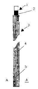
FIGURE 1 shows an illustration of an arc gouging rod in accordance with an
embodiment of the present invention;
FIGURE 2 shows a cross-section of a portion of the rod illustrated in
FIGURE 1;
FIGURE 3 illustrates a cross-section of the entire rod illustrated in FIGURE
1;
and
FIGURE 4 illustrates a jointed rod configured in accordance with the present
invention in use for gouging a workpiece.
2
CA 02501194 2005-03-18
l 9786-P001 US PATENT
DETAILED DESCRIPTION
In the following description, numerous specific details are set forth to
provide
a thorough understanding of the present invention. However, it will be obvious
to
those skilled in the art that the present invention may be practiced without
such
specific details.
Refer now to the drawings wherein depicted elements are not necessarily
shown to scale and wherein like or similar elements are designated by the same
reference numeral through the several views.
Referring to FIGURES 1-3, there is illustrated a jointable hollow carbon rod
with ribs in accordance with an embodiment of the present invention. Carbon
rod 3
includes a tenon (male end) 1 at one end of the rod, which is adaptable for
fitting
inside a rabbeted hole (female end) 8 of another rod so that two or more rods
can be
jointed together end to end. The rabbet hole 8 (also known as a mortise hole)
includes an opening slot 5 so that tenon 1 fits snuggly within rabbet hole 8,
thus
permitting the rabbet hole 8 to expand a bit while the tenon is inserted.
A copper plating layer 4 may be deposited on the outside of the rod 3, with
the
outside layer 4 of the rod having ribs 6 for increasing the electrical
conductivity of the
rod 3. Such a copper layer is also partially inside of the rabbet hole 8 as
shown by
label 7.
Running through the inside of rod 3 is a hollow core 9. On a solid core
gouging rod, the electrode forms a point as the electrode is consumed. This
point on
the end of the solid core gouging rod restricts/limits the ability to conduct
electricity,
since there is very little surface area at the tip of the solid gouging rod.
Since there is
no center on a hollow core rod, as the hollow core electrode is consumed, it
can not
form a point. The electricity on a hollow core rod is spread on the outer and
inner
ring surfaces at the tip of the hollow core gouging rod. This increased
surface area
allows the hollow core rods to conduct significantly more electricity than a
solid core
rod, resulting in a faster, more efficient arc gouging process. Note that the
hollow
core 9 may be continuous throughout the rod 3, or a series of disjointed
hollow cores.
3
CA 02501194 2005-03-18
19786-P001 US PATENT
The rods 3 are adaptable for joining end-to-end, so that a particular arc
gouging process can be continued for a longer period of time before the rod is
consumed. Referring to FIGURE 4, there is illustrated two rods 3 jointed
together
end-to-end at joint 403. Electrical current is supplied to the jointed rods 3
by
clamp 402 in a well known manner. The jointed hollow rods 3 are then utilized
to
gouge workpiece 401, creating gouged portion 404. Since the jointed rods 3 are
longer than a single rod 3, the arc gouging process may be continued for a
longer
period of time before the jointed rods 3 become merely an unusable stub,
resulting in
an ability for the person doing the process to create a more continuous gouge
404.
There are several difficulties in the manufacturing process of hollow, jointed
carbon gouging rods as compared to the manufacturing process of hollow, non-
jointed rods or solid, jointed rods. While none of the challenges presented in
the
individual features of hollow, jointed gouging rods are difficult
individually, it is the
combination of the features: 1) Jointed and 2) Hollow that when combined,
resulted
in a difficult manufacturing challenge. Below is a detailed explanation of the
manufacturing steps, which required extensive testing and process development
to
produce a functioning, safe, and reliable hollow, jointed ribbed carbon
gouging rod.
Adding the ribbed feature can even further increase the manufacturing
difficulty.
A key to a quality, reliable jointed solid carbon gouging rod is the interface
between the two rods. Each rod has a round tenon feature at one end of the rod
and a
mating round mortise hole (also known as a rabbet hole) at the other end of
the rod.
Rods are joined together by inserting the round tenon feature into the mortise
hole of
a second rod. This joint holds the rods together via static friction created
from the
tapered interference fit of the mating features. Most designs incorporate two
slots,
diametrically opposed on the mortise joint, to allow slight expansion of the
mortise
joint. A tolerance must be maintained to create enough interference fit to
hold the
two rods together, but not too much interference which can result in cracking
of the
brittle carbon material. With solid jointed gouging rods, the manufacturing
process
for the joint features is not significantly difficult. However, when adding
the
additional requirement of the hollow feature of the hollow, jointed gouging
rods, the
4
CA 02501194 2005-03-18
19786-P001 US PATENT
center-hole of the hollow rod compromises some of the mechanical strength of
both
the round tenon feature and mating mortise hole.
The hollow center of the rods created cracking of the walls of the mortise
hole, which was not encountered with standard solid jointed rods. To overcome
this
issue, the extrusion pressure is increased to 600 tons, resulting in a denser,
stronger
carbon material. The number of expansion slots in the wall of the mortise hole
has
been reduced from two slots to one slot. The single slot provides more
strength, but
also minimizes the amount of available deflection to accommodate the mating
round
tenon. The tolerances of the inner and outer dimensions/angles of the mortise
wall
needed to be more precise, which requires minimizing temperature variability
and
better packing of raw rods in curing boxes during the curing process in order
to
produce straighter rods. The straighter rods allow for more precise machining
of the
inner and outer dimensions of the mortise hole walls, and when combined with
the
single expansion slot results in a tighter toleranced but mechanically
stronger joint.
1 S The hollow center also created mechanical failure at the base of the tenon
feature of the hollow rods, which was not encountered with standard solid
jointed
rods. To overcome this issue, the extrusion pressure is increased to 600 tans,
resulting in denser, stronger carbon material. The tolerances of the hollow
tenon
outer surface as well as the concentric location of the center hole need to be
more
precise to provide uniform thickness and strength of the hollow tenon wall
(this was
not an issue with a solid, jointed rod). The tighter tolerances of the outer
round
hollow tenon surface required minimizing temperature variability and better
packing
of raw rods in curing boxes during the curing process in order to produce
straighter
rods. The straighter rods allow for more precise machining of the outer
dimensions
of the mortise hole walls. To tighten the axial location of the center hole in
the region
of the tenon, tighter tolerances of the extrusion process and dies are also
required,
which are further complicated by the ribbed feature and the increased 600 ton
extrusion pressures.
5
CA 02501194 2005-03-18
19786-P001 U S PATENT
Combining the hollow, jointed features also creates several difficulties
during
the copper plating process. After the curing process and before the copper
plating
process, wax has to be added to plug the center-hole, while not covering
certain
portions of the tenon and mortise joints. This requires significant testing to
balance
the need of the copper plating (for electrical conductivity) with the need for
no copper
plating on portions of the mating surfaces of the tenon and mortise joints (to
maintain
tight interference fit tolerances on the mating surfaces). After the copper
plating, the
wax needs to be removed from the center hole.
While the manufacturing processes of hollow, non jointed rods or solid,
jointed rods is not significantly difficult individually, combining these two
features in
a hollow, jointed rod provides many manufacturing challenges. Overcoming these
manufacturing challenges requires in-depth manufacturing engineering and
testing to
tighten the tolerances of the manufacturing processes and produce a more
precise and
stronger hollow, jointed gouging rod.
Although the present invention and its advantages have been described in
detail, it should be understood that various changes, substitutions and
alterations can
be made herein without departing from the spirit and scope of the invention as
defined by the appended claims.
6