Sélection de la langue

Search

Sommaire du brevet 2503990 

Énoncé de désistement de responsabilité concernant l'information provenant de tiers

Une partie des informations de ce site Web a été fournie par des sources externes. Le gouvernement du Canada n'assume aucune responsabilité concernant la précision, l'actualité ou la fiabilité des informations fournies par les sources externes. Les utilisateurs qui désirent employer cette information devraient consulter directement la source des informations. Le contenu fourni par les sources externes n'est pas assujetti aux exigences sur les langues officielles, la protection des renseignements personnels et l'accessibilité.

Disponibilité de l'Abrégé et des Revendications

L'apparition de différences dans le texte et l'image des Revendications et de l'Abrégé dépend du moment auquel le document est publié. Les textes des Revendications et de l'Abrégé sont affichés :

  • lorsque la demande peut être examinée par le public;
  • lorsque le brevet est émis (délivrance).
(12) Demande de brevet: (11) CA 2503990
(54) Titre français: METHODE ET APPAREIL PERMETTANT DE SELECTIONNER ET DE SEPARER LES RAMES D'UNE PILE DE FEUILLES DE PAPIER OU D'ARTICLES SEMBLABLES
(54) Titre anglais: METHOD AND UNIT FOR SELECTING AND SEPARATING REAMS FROM A STACK OF SHEETS OF PAPER OR SIMILAR
Statut: Réputée abandonnée et au-delà du délai pour le rétablissement - en attente de la réponse à l’avis de communication rejetée
Données bibliographiques
(51) Classification internationale des brevets (CIB):
  • B65H 03/32 (2006.01)
  • B07C 05/10 (2006.01)
  • B65H 03/46 (2006.01)
  • B65H 07/02 (2006.01)
  • B65H 07/12 (2006.01)
  • B65H 31/12 (2006.01)
  • B65H 33/04 (2006.01)
  • B65H 39/02 (2006.01)
  • B65H 39/045 (2006.01)
  • B65H 39/05 (2006.01)
  • B65H 39/055 (2006.01)
  • B65H 39/065 (2006.01)
  • B65H 39/07 (2006.01)
  • B65H 39/075 (2006.01)
  • B65H 43/08 (2006.01)
  • G06M 09/00 (2006.01)
(72) Inventeurs :
  • CANINI, GABRIELE (Italie)
  • CINOTTI, ANDREA (Italie)
(73) Titulaires :
  • KPL PACKAGING S.P.A.
(71) Demandeurs :
  • KPL PACKAGING S.P.A. (Italie)
(74) Agent: SMART & BIGGAR LP
(74) Co-agent:
(45) Délivré:
(22) Date de dépôt: 2005-04-07
(41) Mise à la disponibilité du public: 2005-10-08
Licence disponible: S.O.
Cédé au domaine public: S.O.
(25) Langue des documents déposés: Anglais

Traité de coopération en matière de brevets (PCT): Non

(30) Données de priorité de la demande:
Numéro de la demande Pays / territoire Date
04425263.3 (Office Européen des Brevets (OEB)) 2004-04-08

Abrégés

Abrégé anglais


A ream is selected and separated from a stack of
sheets by means of a separating member which is inserted
inside the stack at an insertion region defined by images
acquired by a television camera moved vertically to cover
a given scanning region of the stack; a focused portion
of each image acquired by the television camera being
located as a function of the location in the image of a
line projected onto the stack at an angle of incidence of
other than 90°.

Revendications

Note : Les revendications sont présentées dans la langue officielle dans laquelle elles ont été soumises.


9
THE EMBODIMENTS OF THE INVENTION IN WHICH AN EXCLUSIVE
PROPERTY OR PRIVILEGE IS CLAIMED ARE DEFINED AS FOLLOWS:
1) A unit for selecting and separating reams from a
stack of sheets of paper or similar; the stack comprising
a number of sheets stacked in a given direction, and
having a front face substantially parallel to said
direction; the unit comprising a television camera facing
the front face to acquire an image of a portion of the
front face; actuating means for moving the stack and the
television camera with respect to each other to vary the
portion of the front face covered by the television
camera; separating means which are inserted inside the
stack at a given insertion region to separate a ream from
the stack; and control means for counting a number of
sheets in the portion of the front face covered by the
television camera, and for controlling movement of the
insertion region in said direction as a function of the
number of sheets counted by means of the images acquired
by the television camera; the unit being characterized by
comprising an identification device for determining a
focused portion of each image acquired by the television
camera; the control means modifying the analysis of the
image, by which to count the sheets, as a function of the
location of said focused portion in the image.
2) A unit as claimed in Claim 1, wherein the
identification device comprises a linear pointing device
for projecting onto the front face of the stack a line

10
striking the front face at an angle of other than 90°;
the control means analysing the images acquired by the
television camera to locate the projected line in each
image, and modifying the analysis of the image, by which
to count the sheets, as a function of the location of the
projected line in the image.
3) A unit as claimed in Claim 2, wherein, for each
image acquired by the television camera, the control
means determine the focused portion of the image as a
function of the location of the projected line in the
image, and simply analyse the focused portion.
4 ) A unit as claimed in Claim 2 , wherein, for each
image acquired by the television camera, the control
means determine a distance of the relative sheet from the
television camera as a function of the location of the
projected line in the image.
5) A unit as claimed in Claim 1, wherein the
identification device comprises a recognition algorithm
for determining a focused portion of each image acquired
by the television camera.
6) A unit as claimed in Claim 1, wherein the
television camera has an optical axis at a further angle
of other than 90° with respect to said front face.
7) A method of selecting and separating reams from a
stack of sheets of paper or similar; the stack comprising
a number of sheets stacked in a given direction, and
having a front face substantially parallel to said
direction; the method comprising the steps of acquiring

11
an image of a portion of the front face by means of a
television camera facing the front face; moving the stack
and the television camera with respect to each other to
vary the portion of the front face covered by the
television camera; separating a ream from the stack at a
given insertion region; counting a number of sheets in
the portion of the front face covered by the television
camera; and controlling movement of the insertion region
in said direction as a function of the number of sheets
counted by means of the images acquired by the television
camera; the method being characterized by also comprising
the steps of determining a focused portion of each image
acquired by the television camera; and modifying the
analysis of the image, by which to count the sheets, as a
function of the location of said focused portion in the
image.
8) A method as claimed in Claim 7, and comprising
the steps of projecting onto the front face of the stack
a line striking the front face at an angle of other than
90°; analysing the images acquired by the television
camera to locate the projected line in each image; and
modifying the analysis of the image, by which to count
the sheets, as a function of the location of the
projected line in the image.
9) A method as claimed in Claim 8, and also
comprising the steps of determining, for each image
acquired by the television camera, the focused portion of
the image as a function of the location of the projected

12
line in the image; and simply analysing the focused
portion.
10) A method as claimed in Claim 8, and also
comprising the step of determining, for each image
acquired by the television camera, a distance of the
relative sheet from the television camera as a function
of the location of the projected line in the image.
11) A method as claimed in Claim 7, wherein the
focused portion of each image acquired by the television
camera is determined by a recognition algorithm.

Description

Note : Les descriptions sont présentées dans la langue officielle dans laquelle elles ont été soumises.

CA 02503990 2005-04-07
1
METHOD AND UNIT FOR SELECTING AND SEPARATING REAMS FROM A
STACK OF SHEETS OF PAPER OR SIMILAR
The present invention relates to a unit for
selecting and separating reams from a stack of sheets of
paper or similar.
More specifically, the present invention relates to
a unit for selecting and separating reams from a stack of
sheets, of the type comprising a television camera
positioned facing a front face of the stack to acquire an
image of a portion of the front face; an actuating device
for moving the television camera along the stack to vary
the portion of the front face covered by the television
camera; and a separating member which is inserted inside
the stack to separate the reams successively from the
stack.
The images acquired by the television camera are
used by an electronic central control unit to control the
movement of the separating member along the stack, to
count the number of sheets in a ream during said movement
of the separating member, and to arrest the separating
member at the last sheet in the ream to be removed.

CA 02503990 2005-04-07
2
Once positioned at the last sheet in the ream to be
removed, the separating member is moved into contact with
the stack at a given insertion region, and is inserted
inside the stack to separate the ream from the stack.
Known units of the type described above have various
drawbacks, mainly on account of the fact that, when the
front face of the stack has an undulated, other than
perfectly flat profile, and the television camera is
oriented at a given angle with respect to the front face,
to the electronic central control unit is unable to locate
the focused portion of each image acquired by the
television camera.
It is an object of the present invention to provide
a unit for selecting and separating reams from a stack of
sheets of paper or similar, designed to eliminate the
aforementioned drawbacks, and which is cheap and easy to
produce.
According to the present invention, there is
provided a unit for selecting and separating reams from a
stack of sheets of paper or similar, as claimed in Claim
1.
The present invention also relates to a method of
selecting and separating reams from a stack of sheets of
paper or similar.
According to the present invention, there is
provided a method of selecting and separating reams from
a stack of sheets of paper or similar, as claimed in
Claim 7.

CA 02503990 2005-04-07
3
A non-limiting embodiment of the present invention
will be described by way of example with reference to the
accompanying drawings, in which:
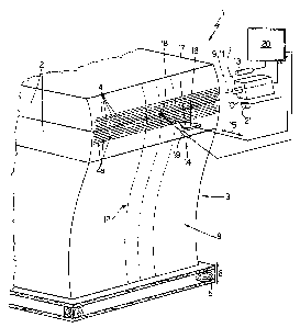
Figure 1 shows a schematic view in perspective, with
parts removed for clarity, of a preferred embodiment of
the unit according to the present invention;
Figure 2 shows a schematic side view, with parts
removed for clarity, of the Figure 1 unit;
Figure 3 shows a schematic front view, with parts
removed for clarity, of the Figure 1 unit;
Figure 4 shows a schematic plan view, with parts
removed for clarity, of the Figure 1 unit;
Figure 5 shows a side view of a stack of sheets in
two different configurations;
Figure 6 shows a front view, with parts enlarged for
clarity, of a portion of the stack of sheets in Figure 5.
With reference to Figures 1 to 3, number 1 indicates
as a whole a unit for selecting and separating reams 2
from a stack 3 of sheets 4 supported on a pallet 5 and
comprising a number of sheets 4 stacked in a vertical
direction 6.
Unit 1 comprises an optical image-acquisition device
7 positioned facing a front face 8 of stack 3, and in
turn comprising a first slide (not shown) movable in
direction 6; a second slide (not shown) connected in
known manner to the first slide (not shown) to move
linearly in a horizontal direction 9 crosswise to
direction 6; and a television camera 10 mounted on the

CA 02503990 2005-04-07
4
second slide (not shown), having an optical axis 11
parallel to direction 9, and for covering a portion 8a of
face 8.
Moving television camera 10 in direction 6 provides
for varying portion 8a of face 8 covered by television
camera 10, and for covering as a whole a scanning region
12 which can be illuminated by a light source 13.
In connection with the above, it should be pointed
out that direction 9 and, therefore, axis 11 form an
angle a (Figure 4) of other than 90° with face 8, which,
unless otherwise stated, will be considered a flat face
parallel to direction 6.
Obviously, in variations not shown:
television camera 10 is fixed in direction 6, and
stack 3 is movable in direction 6;
television camera 10 is mounted to scan sheets 4 by
oscillating about a given axis of rotation.
Unit 1 also comprises a separating device 14 for
separating reams 2 from stack 3, and which in turn
2o comprises a first slide (not shown) movable in direction
6; a second slide (not shown) connected in known manner
to the first slide (not shown) to move linearly in a
direction 15 perpendicular to face 8; and a separating
member 16 mounted on the second slide (not shown).
Member 16 is defined by a substantially flat, wedge-
shaped blade 17 which is inserted inside stack 3 at a
substantially spot-shaped insertion region 18 lying in
scanning region 12 of television camera 10, and whose

CA 02503990 2005-04-07
location on face 8 is indicated, when blade 17 is located
a given distance from face 8, by a laser pointing device
19 integral with member 16 and for illuminating a portion
of face 8 coincident with region 18.
5 In actual use, television camera 10 is moved in
direction 6 to acquire, within scanning region 12, the
images of a number of sheets 4 normally approximating in
excess the number of sheets 4 in a ream 2. The images
acquired by television camera 10 are used by an-
electronic central control unit 20 to control the
movement of blade 17 and, therefore, of insertion region
18 in direction 6, to count sheets 4 as blade 17 moves in
direction 6, and to arrest blade 17 in direction 6 once
blade 17 is positioned at the last sheet 4 in the ream 2
to be selected and removed.
At this point, blade 17 is moved in direction 15 and
inserted inside stack 3 at region 18 to separate the ream
2 considered from stack 3.
Since television camera 10 and blade 17 are so
oriented with respect to each other that insertion region
18 lies in scanning region 12, insertion region 18 is
always located within portion 8a of face 8 covered by
television camera 10. Consequently, when blade 17 is
arrested in direction 6, insertion region 18 is always
located correctly at the last sheet 4 in the ream 2 to be
removed, regardless of the shape of sheets 4, i.e.
regardless of whether the profile of sheets 4 is
perfectly flat or undulated.

CA 02503990 2005-04-07
6
Since face 8 may possibly be undulated, i.e. other
than perfectly flat, central control unit 20 also
provides, as television camera 10 moves in direction 6,
for continuously feedback-controlling the movement of
television camera 10 in direction 9 in response to a
signal from a distance sensor 21 integral with television
camera 10. Moving television camera 10 in direction 9
provides for maintaining a substantially constant
distance, measured parallel to direction 9, between face
l0 8 and television camera 10, and so enabling television
camera 10 to fully exploit its ability to focus the
acquired images.
As shown in Figure 4, the ability to focus the
images acquired by television camera 10 varies in
direction 15 alongside a variation in the orientation of
optical axis 11 with respect to a vertical reference
plane P perpendicular to direction 15.
That is, when optical axis 11 is parallel to
direction 15, television camera 10 is able to correctly
focus all the sheets 4 whose sides 4a facing television
camera 10 are located at most a given distance "a" from
plane P. On the other hand, when optical axis 11 is
parallel to direction 9 and, therefore, at an angle a of
other than 90° with respect to plane P, television camera
10 is able to correctly focus all the sheets 4 whose
sides 4a facing television camera 10 are located at most
at a distance which is obviously again distance "a" if
measured in direction 9, and which is a distance "b",

CA 02503990 2005-04-07
7
greater than "a", if measured in direction 15.
For each side 4a located at most at distance "b"
from plane P, television camera 10 therefore acquires an
image having, within scanning region 12, a correctly
focused portion T1, and a blurred portion T2 (Figures 4
and 6 ) .
To locate each portion T1, central control unit 20
cooperates with a laser pointing device 22 located on the
opposite side of blade 17 to television camera 10, and
which projects onto face 8 and within scanning region 12
a line 23 striking face 8 at an angle (3 of other than 90°
(Figure 4).
As shown in Figures 4, 5 and 6, when face 8 is flat
and coplanar with plane P (as shown by the dash line in
Figure 5), line 23 intersects side 4a of each sheet 4 at
a point Pl lying in plane P (Figure 4), and is therefore
straight and parallel to direction 6 (as shown by the
dash line in Figure 6).
Conversely, when face 8 has an undulated profile (as
shown by the continuous line in Figure 5), line 23
intersects side 4a of each sheet 4 at a point P2 which is
shifted rightwards with respect to the corresponding
point P1 when side 4a projects from plane P towards
television camera 10 (Figure 4), and which is shifted
leftwards with respect to the corresponding point P1 when
side 4a is located on the opposite side of plane P to
television camera 10 (Figure 4), so that line 23 has a
curved profile (as shown by the continuous line in Figure

CA 02503990 2005-04-07
g
6) .
Central control unit 20 therefore analyses the
images acquired by television camera 10 to locate line 23
in each image, and so locates relative portion T1 as a
function of the location of line 23 in the image.
Once each portion T1 is located, central control
unit 20 counts sheets 4 solely as a function of the
analysis of portions T1.
By locating line 23, sensor 21 can be eliminated,
l0 and central control unit 20 can calculate the distance of
each side 4a from plane P, and therefore from television
camera 10, either directly by means of a computing unit
within central control unit 20, or indirectly by means of
a matrix memorized in central control unit 20.
In a variation not shown, Laser pointing device 22
is replaced by a recognition algorithm implemented in
electronic central control unit 20.

Dessin représentatif
Une figure unique qui représente un dessin illustrant l'invention.
États administratifs

2024-08-01 : Dans le cadre de la transition vers les Brevets de nouvelle génération (BNG), la base de données sur les brevets canadiens (BDBC) contient désormais un Historique d'événement plus détaillé, qui reproduit le Journal des événements de notre nouvelle solution interne.

Veuillez noter que les événements débutant par « Inactive : » se réfèrent à des événements qui ne sont plus utilisés dans notre nouvelle solution interne.

Pour une meilleure compréhension de l'état de la demande ou brevet qui figure sur cette page, la rubrique Mise en garde , et les descriptions de Brevet , Historique d'événement , Taxes périodiques et Historique des paiements devraient être consultées.

Historique d'événement

Description Date
Demande non rétablie avant l'échéance 2009-04-07
Le délai pour l'annulation est expiré 2009-04-07
Réputée abandonnée - omission de répondre à un avis sur les taxes pour le maintien en état 2008-04-07
Inactive : CIB de MCD 2006-03-12
Lettre envoyée 2005-10-27
Demande publiée (accessible au public) 2005-10-08
Inactive : Page couverture publiée 2005-10-07
Inactive : Transfert individuel 2005-10-05
Inactive : CIB attribuée 2005-08-18
Inactive : CIB en 1re position 2005-06-29
Inactive : CIB attribuée 2005-06-29
Inactive : Lettre de courtoisie - Preuve 2005-05-24
Inactive : Certificat de dépôt - Sans RE (Anglais) 2005-05-17
Demande reçue - nationale ordinaire 2005-05-16

Historique d'abandonnement

Date d'abandonnement Raison Date de rétablissement
2008-04-07

Taxes périodiques

Le dernier paiement a été reçu le 2007-03-19

Avis : Si le paiement en totalité n'a pas été reçu au plus tard à la date indiquée, une taxe supplémentaire peut être imposée, soit une des taxes suivantes :

  • taxe de rétablissement ;
  • taxe pour paiement en souffrance ; ou
  • taxe additionnelle pour le renversement d'une péremption réputée.

Les taxes sur les brevets sont ajustées au 1er janvier de chaque année. Les montants ci-dessus sont les montants actuels s'ils sont reçus au plus tard le 31 décembre de l'année en cours.
Veuillez vous référer à la page web des taxes sur les brevets de l'OPIC pour voir tous les montants actuels des taxes.

Historique des taxes

Type de taxes Anniversaire Échéance Date payée
Taxe pour le dépôt - générale 2005-04-07
Enregistrement d'un document 2005-10-05
TM (demande, 2e anniv.) - générale 02 2007-04-10 2007-03-19
Titulaires au dossier

Les titulaires actuels et antérieures au dossier sont affichés en ordre alphabétique.

Titulaires actuels au dossier
KPL PACKAGING S.P.A.
Titulaires antérieures au dossier
ANDREA CINOTTI
GABRIELE CANINI
Les propriétaires antérieurs qui ne figurent pas dans la liste des « Propriétaires au dossier » apparaîtront dans d'autres documents au dossier.
Documents

Pour visionner les fichiers sélectionnés, entrer le code reCAPTCHA :


Pour visualiser une image, cliquer sur un lien dans la colonne description du document (Temporairement non-disponible). Pour télécharger l'image (les images), cliquer l'une ou plusieurs cases à cocher dans la première colonne et ensuite cliquer sur le bouton "Télécharger sélection en format PDF (archive Zip)" ou le bouton "Télécharger sélection (en un fichier PDF fusionné)".

Liste des documents de brevet publiés et non publiés sur la BDBC .

Si vous avez des difficultés à accéder au contenu, veuillez communiquer avec le Centre de services à la clientèle au 1-866-997-1936, ou envoyer un courriel au Centre de service à la clientèle de l'OPIC.

({010=Tous les documents, 020=Au moment du dépôt, 030=Au moment de la mise à la disponibilité du public, 040=À la délivrance, 050=Examen, 060=Correspondance reçue, 070=Divers, 080=Correspondance envoyée, 090=Paiement})


Description du
Document 
Date
(aaaa-mm-jj) 
Nombre de pages   Taille de l'image (Ko) 
Abrégé 2005-04-06 1 14
Description 2005-04-06 8 280
Revendications 2005-04-06 4 137
Dessins 2005-04-06 3 81
Dessin représentatif 2005-09-12 1 14
Certificat de dépôt (anglais) 2005-05-16 1 157
Courtoisie - Certificat d'enregistrement (document(s) connexe(s)) 2005-10-26 1 106
Rappel de taxe de maintien due 2006-12-10 1 112
Courtoisie - Lettre d'abandon (taxe de maintien en état) 2008-06-01 1 173
Correspondance 2005-05-16 1 27
Taxes 2007-03-18 1 30