Sélection de la langue

Search

Sommaire du brevet 2506449 

Énoncé de désistement de responsabilité concernant l'information provenant de tiers

Une partie des informations de ce site Web a été fournie par des sources externes. Le gouvernement du Canada n'assume aucune responsabilité concernant la précision, l'actualité ou la fiabilité des informations fournies par les sources externes. Les utilisateurs qui désirent employer cette information devraient consulter directement la source des informations. Le contenu fourni par les sources externes n'est pas assujetti aux exigences sur les langues officielles, la protection des renseignements personnels et l'accessibilité.

Disponibilité de l'Abrégé et des Revendications

L'apparition de différences dans le texte et l'image des Revendications et de l'Abrégé dépend du moment auquel le document est publié. Les textes des Revendications et de l'Abrégé sont affichés :

  • lorsque la demande peut être examinée par le public;
  • lorsque le brevet est émis (délivrance).
(12) Brevet: (11) CA 2506449
(54) Titre français: MATERIAU D'APPUI DE PROFILE EN J
(54) Titre anglais: J-CHANNEL BACKER MATERIAL
Statut: Périmé et au-delà du délai pour l’annulation
Données bibliographiques
(51) Classification internationale des brevets (CIB):
  • E06B 01/04 (2006.01)
  • E04F 21/165 (2006.01)
(72) Inventeurs :
  • COLLINS, P. MICHAEL (Etats-Unis d'Amérique)
(73) Titulaires :
  • PACC SYSTEMS I.P., LLC
(71) Demandeurs :
  • PACC SYSTEMS I.P., LLC (Etats-Unis d'Amérique)
(74) Agent: MACRAE & CO.
(74) Co-agent:
(45) Délivré: 2013-04-30
(22) Date de dépôt: 2005-05-06
(41) Mise à la disponibilité du public: 2006-05-16
Requête d'examen: 2010-03-11
Licence disponible: S.O.
Cédé au domaine public: S.O.
(25) Langue des documents déposés: Anglais

Traité de coopération en matière de brevets (PCT): Non

(30) Données de priorité de la demande:
Numéro de la demande Pays / territoire Date
10/989,790 (Etats-Unis d'Amérique) 2004-11-16

Abrégés

Abrégé français

Un élément de finition pour des murs en maçonnerie permet une installation simple et un placement précis du produit de calfeutrage autour des fenêtres et des portes dans une construction à murs creux. Cette invention convient à une vaste gamme de profils de fenêtre ou de cadre de porte, particulièrement ceux qui présentent un profil orienté vers l'extérieur, comme les cadres à profil en J, pour le travail inhérent aux détails et à la finition nécessaire pour l'installation appropriée d'une fenêtre ou d'une porte dans une construction à placage en maçonnerie ou à murs creux sans nécessiter une installation de haute spécialisation et à forte main-d'ouvre.


Abrégé anglais

A finishing member for masonry walls allows for simple installation and accurate placement of caulking around windows and doors in cavity wall construction. This invention accommodates a wide variety of window or door frame profiles, particularly those having an outwardly directed channel such as so called J-channel frames, for the detailing and finishing work required for proper installation of a window or door into a masonry veneer or cavity wall construction without requiring a highly skilled and labor intensive installation.

Revendications

Note : Les revendications sont présentées dans la langue officielle dans laquelle elles ont été soumises.


CLAIMS: -11-
1. A cavity wall construction comprising:
a first wall;
a second wall generally parallel to and spaced from the first wall;
wherein the second wall is comprised of courses of masonry units held
together with mortar;
an opening in the first and second walls, the opening including spaced
jambs on opposite sides of the opening;
a frame sized and configured to fit within the opening, the frame having
an outwardly directed channel; and
at least one finishing member positioned at a juncture between the frame
and one of the jambs of the opening, a first leg of the finishing member being
interposed in the outwardly directed channel of the frame and a second leg of
the finishing member being juxtaposed to the second wall to thereby provide a
transition from the frame to the second wall;
the finishing member further comprising a terminal end portion and a
frangible connection joining the terminal end portion to a remainder of the
finishing member;
wherein the terminal end portion is adapted to be removed along the
frangible connection and thereby reveal a recess at a juncture adjacent to the
frame, the remainder of the finishing member and one of the jambs of the
opening.

-12-
2. The cavity wall construction of claim 1 further comprising:
a bead of caulk positioned in the recess and sealing the juncture
between the frame and the second wall.
3. The cavity wall construction of claim 1 wherein the first and second legs
are generally perpendicular to each other.
4. The cavity wall construction of claim 1 wherein the opening is one of a
window opening and a door opening and the frame is a J-channel frame for one
of a window and a door.
5. The cavity wall construction of claim 1 wherein the finishing member is a
closed cell foam material and the frangible connection comprises perforations
in
the closed cell foam material.

-13-
6. A cavity wall construction comprising:
a first wall;
a second wall generally parallel to and spaced from the first wall;
wherein the second wall is comprised of courses of masonry units held
together with mortar;
an opening in the first and second walls, the opening including spaced
jambs on opposite sides of the opening;
a frame sized and configured to fit within the opening, the frame having
an outwardly directed channel;
wherein the opening is one of a window opening and a door opening and
the frame is a J-channel frame for one of a window and a door;
at least one finishing member positioned at a juncture between the frame
and one of the jambs of the opening, a first leg of the finishing member being
interposed in the outwardly directed channel of the frame and a second leg of
the finishing member being juxtaposed to the second wall to thereby provide a
transition from the frame to the second wall;
a terminal end portion of the second leg;
a frangible connection joining the terminal end portion to a remainder of
the finishing member;
wherein the terminal end portion is adapted to be removed along the
frangible connection and thereby reveal a recess adjacent to the frame, the
remainder of the finishing member and one of the jambs of the opening; and
a bead of caulk positioned in the recess and sealing the juncture
between the frame and the second wall.

-14-
7. A method of constructing a wall comprising the steps of:
erecting a first wall having an opening therein, the opening being
bounded by at least one jamb;
mounting a frame within the opening, the frame having an outwardly
directed channel;
mounting a finishing member to the frame along the jamb, the finishing
member having a first leg and a second leg, wherein the second leg comprises
a terminal end portion joined to a remainder of the finishing member by a
frangible connection;
inserting the first leg into the outwardly directed channel of the frame;
juxtaposing the second leg of the finishing member to the first wall and
thereby provide a transition from the frame to the first wall at the opening;
and
removing the terminal end portion of the second leg along the frangible
connection and thereby exposing a recess at a juncture adjacent to the frame,
the remainder of the finishing member and the jamb of the opening.
8. The method of claim 7 further comprising:
erecting a second wall spaced from the first wall, the frame being
mounted to on outer face of the second wall confronting the first wall.
9. The method of claim 7 wherein the first wall is erected with masonry
units held together with mortar, the method further comprising:
juxtaposing one of the masonry units and the mortar to the second leg of
the finishing member.
10. The method of claim 7 further comprising:
applying a bead of caulk in the recess.

-15-
11. A frame assembly adapted to be installed into an opening in a wall, the
frame assembly comprising:
a frame sized and configured to fit within the opening, the frame having
an outwardly directed channel along at least one side thereof; and
at least one finishing member adapted to be positioned at a juncture
between the frame and a jamb adjacent to the opening, the finishing member
having a first leg interposed in the outwardly directed channel of the frame
and
a second leg of the finishing member adapted to be juxtaposed to the wall to
thereby provide a transition from the frame to the wall;
the finishing member further comprising a terminal end portion and a
frangible connection joining the terminal end portion to a remainder of the
finishing member;
wherein the terminal end portion is adapted to be removed along the
frangible connection and thereby reveal a recess at a juncture adjacent to the
frame, the remainder of the finishing member and one of the jambs of the
opening.
12. The frame assembly of claim 11 wherein the first and second legs are
generally perpendicular to each other.
13. The frame assembly claim 11 wherein the frame is a J-channel frame,
the frame assembly further comprising:
one of a window and a door mounted in the frame.

-16-
14. The frame assembly of claim 11 wherein the finishing member is a
closed cell foam material and the frangible connection comprises perforations
in
the closed cell foam material.

Description

Note : Les descriptions sont présentées dans la langue officielle dans laquelle elles ont été soumises.


CA 02506449 2012-01-05
J-CHANNEL BACKER MATERIAL
Background of the Invention This invention relates to masonry veneer
or cavity wall
j
construction and, more particularly, to devices used in association with
window
and door installations in a veneer/cavity wall system for proper transition
between the window or door installation and the masonry veneer.
Wall systems having a masonry exterior are typically constructed
of at least one vertical layer of masonry and at least a second vertical layer
of a
material forming a back-up system. The back-up system may be constructed of
lumber, light gauge steel studs or of a concrete masonry unit. The masonry and

CA 02506449 2005-05-06
-2-
back-up system are typically bonded together by horizontal metallic ties
spaced
apart vertically. A space is often provided in such wall systems (e.g., cavity
wall
systems) between the masonry and back-up system for moisture drainage.
Normally, a 1 to 2 inch air space between the masonry and back-up system is
adequate to provide drainage. Insulation may also be placed in the space to
improve the energy efficiency of masonry buildings.
Masonry veneer, and cavity wall construction in general, has
many advantages and is commonly utilized in residential and commercial
construction. Problems often arise during construction, however, in
maintaining a proper transition between the wall structure and window, door
and other openings or discontinuities in the wall. For example, the
dimensioning of the window or door frame installed in the wall is frequently
different and incompatible with the thickness, geometry and dimensions of the
masonry veneer or cavity wall construction. Caulk is often used along the wall
jamb and header in an effort to provide a water tight seal and aesthetic
transition to the window or door frame.
One example of a window or door frame is called a J-channel
frame which has an outwardly directed open channel along the jamb portions of
the frame. The J-channel frame is specifically designed for use on siding clad
exterior walls and not masonry exterior walls. The often rough cut ends of the
siding are inserted into and concealed within the channel of the frame to
present a neat and finished appearance at the transition from the wall to the
frame. Nevertheless, the J-channel frame is often used with masonry walls for
a variety of reasons. In such cases, the channel is vacant and must be flashed

CA 02506449 2005-05-06
-3-
for a proper installation and must receive a backer material for the effective
placement of caulking and sealant.
However, due to the incompatibility of the J-channel frame with
the masonry veneer, effective and aesthetic caulk application is nearly
impossible. As a result, the detailing and finishing work required for proper
installation of a window or door into a masonry veneer or cavity wall
construction is typically very labor intensive, non-uniform and highly
dependent
upon the skill and experience of the particular contractor or tradesman
performing the installation particularly when a J-channel is used. Because of
the importance and wide spread popularity of such masonry structures, a better
method for proper and consistent installation of windows and doors in such
construction is needed.
Summary of the Invention
This invention provides a solution to these and other problems in
the art and allows an efficient and reliable installation for a water tight
and an
aesthetically pleasing transition from surrounding the window or door to the
masonry veneer. Generally, in one embodiment this invention includes a
backer unit or finishing member installed adjacent the J-channel window frame
or door frame to provide a proper transition from the frame to the masonry
wall
structure. In one embodiment, the finishing member has a generally L-shaped
configuration with a first leg of the member being mounted in the cavity
defined
by the channel of the J-channel frame. The second leg of the finishing member
projects generally perpendicularly from the first leg and between the forward
edge of the window or door J-channel frame and the masonry outer wall. In

CA 02506449 2005-05-06
-4-
one embodiment, the first leg is frangibly joined to the second leg by a
perforated joint for selective separation of the second leg from the first
leg.
After the finishing member is installed adjacent to the frame and
the inner and outer wall construction is complete, the terminal end portion of
the
second leg is removed by being torn along the frangible joint. After the
terminal
end portion is removed, a recess is exposed at a juncture with the frame and
the remainder of the finishing member. A bead of caulk or similar finishing
material is applied in the recess to provide a smooth and aesthetically
pleasing
transition from the J-channel frame to the masonry wall. Additionally, the
juncture between the frame and the wall is sealed by the caulk bead to inhibit
and/or prevent the entry of moisture or other foreign material and the void in
the
J-channel is substantially filled.
Advantageously, the finishing member is readily adaptable for use
with a wide variety of window and door J-channel or other frame designs and
construction specifications without requiring highly skilled or specialized
installation and construction techniques.
Brief Description Of The Drawings
The objectives and features of the invention will become more
readily apparent from the following detailed description taken in conjunction
with the accompanying drawings in which:
FIG.1 is an exemplary view of a window installation in a masonry
wall;

CA 02506449 2005-05-06
-5-
FIG. 2 is a perspective cross sectional view taken along line 2-2 in
FIG. 1 of a transition between the wall jamb and a J-channel window frame
according to one embodiment of this invention;
FIG. 3 is a cross sectional plan view taken along line 2-2 of FIG. 1
showing the transition between the wall jamb and window frame shown in FIG.
2; and
FIG. 4 is a perspective view of a finishing member according to
one embodiment of this invention adapted to be used in the frame of FIGS. 1-3.
Detailed Description of the Invention Referring to FIG. 1, an exemplary window
installation 10 in a
masonry wall 12 is shown. The window installation 10 includes a perimeter
window frame 14, one or more window panes 16, and a window opening 18 in
the wall defined by a pair of jambs 20 and a header 22 above and a sill 24
below the window frame 14. Although one example of a window installation is
shown in FIG. 1, this invention is readily applicable for a variety of closure
elements in openings in the wall such as other types of window installations,
frame designs, doors and the like.
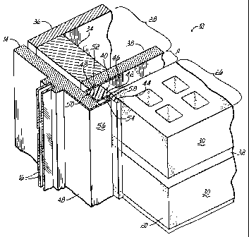
As shown more clearly in FIGS. 2-3, the masonry wall 12 for the
exterior of a building, in one embodiment, is comprised of an outer wall of
masonry or brick veneer 26 and an insulated interior wall 28. The brick veneer
outer wall 26 is constructed from a plurality of bricks or blocks 30 arranged
in a
vertical pattern. Each brick 30 is of a substantially rectangular shape having
a
uniform length, height and depth. The brick veneer 26 is built up by placing
one
layer of bricks 30 over another layer, with the upper layer vertically offset
from

CA 02506449 2012-01-05
-6-
the lower layer by a distance of approximately one-half the length of a brick
30.
Thus, as shown in FIG. 1, a brick 30 on one layer is positioned directly over
the
space between two bricks 30 on the layer immediately beneath it. The spaces
between adjacent bricks 30 and between adjacent layers of bricks are filled
with
mortar 32. Alternatively, the veneer 26 may be stone or other masonry
components.
The interior wall 28 includes wood framing studs 34, dry wall 36,
and outer sheathing material 38. Other materials may be used as is well known
in the art. For example, a liner board (not shown) as disclosed in U.S. Patent
No. 7,421,826 issued September 9, 2008, may be used on the outer sheathing
material 38. In any event, the building wall 12 is constructed so that there
is a
small cavity of airspace A between the back side of the brick veneer 26 and
the
outer surface of the interior wall 28. The airspace A between the back side of
the
brick veneer 26 and the surface of the interior wall 28 is usually at least
about
one to two inches deep, although the exact dimension may vary depending upon
the nature of the construction.
Referring to FIGS. 2-4, a first embodiment of a finishing member
40 is shown installed in the installation 10 to provide a proper transition
from
the window frame 14 to the wall 12. The member 40 is installed along the
jambs 20 of the window opening 18 in cooperation with the corresponding
portions of the window frame 14. As shown in FIGS. 2 and 3, a nailing flange
46 is typically provided from the portion of the window frame 14 adjacent the
jamb 20 and extending to the outer surface of the inner wall 28. Nails or
other
mechanical fasteners (not shown) are inserted through the nailing flange 46

CA 02506449 2005-05-06
-7-
into the sheathing material 38, thereby securing the window frame 14 in
position.
The cross-sectional configuration of the J-channel frame 14
includes an outwardly directed open channel 48 joined to the proximal end of
the nailing flange 46 along the jamb portion. As previously stated, the J-
channel frame 14 and the outwardly open channel 48 are typically intended for
use with siding clad walls in which the rough cut edges of the siding are
inserted into the open channel 48 and concealed therein for a finished and
aesthetically pleasing appearance to the installation. Nevertheless, commonly
the J-channel frame design is utilized with masonry walls 12 and previously
the
channel 48 was improperly flashed or sealed or not filled at all.
The channel 48 is generally U-shaped in which a bight portion 50
of the channel 48 separates a pair of channel side walls 52, 54. A forward
most
surface 56 of the J-channel frame 14 is separated from the adjacent channel
side wall 54 by a connecting leg 58 of the frame 14 as shown in FIGS. 2-3.
In one embodiment, the finishing member 40 is generally L-
shaped, in which a first leg 42 of the member 40 is inserted into the channel
48
of the frame 14, and a second leg 44 of the member 40 projects generally
perpendicular to the plane of the wall 12 and is juxtaposed to the outer wall
or
veneer 26 at the window opening 18 to provide a transition from the window
frame 14 to the wall 12. Commonly, a standard backer rod is used to fill a gap
between a frame and the wall 12 and provide a surface on which caulk or other
sealant can be applied to provide a sealed transition between the standard
frame and the wall 12. However, the gap and spacing between the J-channel
frame 14 and the wall 12 is significantly larger, deeper (on the order of 1/8
to

CA 02506449 2005-05-06
-8-
1/4 inch or greater) and of a geometry that is not compatible for standard
backer rod materials. The standard backer rod materials would not be secure
in the gap nor provide a stable backing for the application of the caulk or
sealant. Therefore, a proper transition from the window frame 14 to the wall
12
that is effectively sealed against wind, rain, and other elements as well as
aesthetically pleasing is often difficult if not impossible. The wide variety,
sizes
and configurations of window frames 14 available from various manufacturers
increases the complexity and difficulty with providing a proper transition
from
the window frame 14 to the wall 12. Nevertheless, the finishing member 40 of
this invention provides a solution.
The finishing member 40 also allows for expansion and
contraction of the window frame 14 relative to the wall 12 during a variety of
climatic conditions. In one embodiment, the member 40 is made of closed cell
foam and bends, contracts, expands or deflects to accommodate of the wall 12
relative to the frame 14. In combination with the beads of caulk as
appropriate,
the finishing member 40 of this invention serves as a backer material and
provides for a durable, reliable, easily installed and sealed transition from
the
window frame 14 to the wall 12. In certain other embodiments, the member 40
is extruded from a variety of thermoplastic or other polymeric materials.
Alternatively, the member 40 may be aluminum or other materials resistant to
rust and weather.
In one embodiment of the invention, the leg 42 of the member 40
is approximately 7/8" in length and 5/8" thick; whereas the leg 44 is
approximately 5/8" in length and 1/4" thick, although other dimensions of the

CA 02506449 2005-05-06
-9-
member 40 are possible within this invention as compatible with the frame 14
configurations and sizes.
Referring to FIG. 4, a perspective view of the finishing member
40, according to this invention, is shown. In this embodiment, the member 40
is
generally L-shaped in which the first leg 42 is adapted to mount to the frame
14
and be inserted in the channel 48, and the second leg 44 of the member 40
projects generally perpendicular to provide a transition from the frame 14 to
the
wall 12. The second leg 44 is constructed of closed cell foam and includes a
terminal end portion 60 joined to a remainder of the member 40 by a frangible
connection 62 such as a series of perforations to provide for the convenient
and easy removal of the terminal end portion 60. The second leg 44 may
include multiple spaced connections 62 for use with a variety of
configurations.
During installation of the finishing member 40 and in construction
of the cavity wall 12, the inner wall 28 is constructed with an opening 18 for
the
window, door or other installation. The frame 14, is inserted into the opening
18 and the member 40 is mounted to the channel of the frame 14 as previously
described. The outer veneer wall 26 is constructed with courses of masonry
units 30 and mortar 32. After construction of the outer veneer wall 26 is
completed, the terminal end portion 60 of the second leg 44 may be removed
along the frangible connection 62 thereby exposing a recess at the juncture
between the frame 14, the remainder of the member 40 and the wall 12. As
shown in FIG. 3, the recess may be filled with a bead of caulk 64 to provide
an
aesthetically pleasing transition from the frame 14 to the wall 12, as well as
sealing the juncture between the frame 14 and the wall 12.

. .
CA 02506449 2005-05-06
From the above disclosure of the general principles of the present -10-
invention and the preceding detailed description of at least one preferred
embodiment, those skilled in the art will readily comprehend the various
modifications to which this invention is susceptible. Therefore, I desire to
be
limited only by the scope of the following claims and equivalents thereof.
I claim:

Dessin représentatif
Une figure unique qui représente un dessin illustrant l'invention.
États administratifs

2024-08-01 : Dans le cadre de la transition vers les Brevets de nouvelle génération (BNG), la base de données sur les brevets canadiens (BDBC) contient désormais un Historique d'événement plus détaillé, qui reproduit le Journal des événements de notre nouvelle solution interne.

Veuillez noter que les événements débutant par « Inactive : » se réfèrent à des événements qui ne sont plus utilisés dans notre nouvelle solution interne.

Pour une meilleure compréhension de l'état de la demande ou brevet qui figure sur cette page, la rubrique Mise en garde , et les descriptions de Brevet , Historique d'événement , Taxes périodiques et Historique des paiements devraient être consultées.

Historique d'événement

Description Date
Le délai pour l'annulation est expiré 2015-05-06
Lettre envoyée 2014-05-06
Accordé par délivrance 2013-04-30
Inactive : Page couverture publiée 2013-04-29
Inactive : Taxe finale reçue 2013-02-14
Préoctroi 2013-02-14
Un avis d'acceptation est envoyé 2012-10-01
Lettre envoyée 2012-10-01
Un avis d'acceptation est envoyé 2012-10-01
Inactive : Approuvée aux fins d'acceptation (AFA) 2012-09-28
Modification reçue - modification volontaire 2012-06-12
Inactive : Dem. de l'examinateur par.30(2) Règles 2012-02-27
Modification reçue - modification volontaire 2012-01-05
Inactive : Dem. de l'examinateur art.29 Règles 2011-07-21
Inactive : Dem. de l'examinateur par.30(2) Règles 2011-07-21
Modification reçue - modification volontaire 2010-05-18
Lettre envoyée 2010-04-07
Exigences pour une requête d'examen - jugée conforme 2010-03-11
Toutes les exigences pour l'examen - jugée conforme 2010-03-11
Requête d'examen reçue 2010-03-11
Demande publiée (accessible au public) 2006-05-16
Inactive : Page couverture publiée 2006-05-15
Lettre envoyée 2005-09-08
Inactive : CIB en 1re position 2005-08-02
Inactive : Transfert individuel 2005-07-18
Inactive : CIB attribuée 2005-07-12
Inactive : CIB en 1re position 2005-07-12
Inactive : CIB attribuée 2005-07-12
Inactive : Certificat de dépôt - Sans RE (Anglais) 2005-06-17
Inactive : Lettre de courtoisie - Preuve 2005-06-14
Demande reçue - nationale ordinaire 2005-06-10
Inactive : Certificat de dépôt - Sans RE (Anglais) 2005-06-10
Déclaration du statut de petite entité jugée conforme 2005-05-06

Historique d'abandonnement

Il n'y a pas d'historique d'abandonnement

Taxes périodiques

Le dernier paiement a été reçu le 2013-04-18

Avis : Si le paiement en totalité n'a pas été reçu au plus tard à la date indiquée, une taxe supplémentaire peut être imposée, soit une des taxes suivantes :

  • taxe de rétablissement ;
  • taxe pour paiement en souffrance ; ou
  • taxe additionnelle pour le renversement d'une péremption réputée.

Les taxes sur les brevets sont ajustées au 1er janvier de chaque année. Les montants ci-dessus sont les montants actuels s'ils sont reçus au plus tard le 31 décembre de l'année en cours.
Veuillez vous référer à la page web des taxes sur les brevets de l'OPIC pour voir tous les montants actuels des taxes.

Historique des taxes

Type de taxes Anniversaire Échéance Date payée
Taxe pour le dépôt - petite 2005-05-06
Enregistrement d'un document 2005-07-18
TM (demande, 2e anniv.) - petite 02 2007-05-07 2007-03-23
TM (demande, 3e anniv.) - petite 03 2008-05-06 2008-03-31
TM (demande, 4e anniv.) - petite 04 2009-05-06 2009-03-20
Requête d'examen - petite 2010-03-11
TM (demande, 5e anniv.) - petite 05 2010-05-06 2010-03-24
TM (demande, 6e anniv.) - petite 06 2011-05-06 2011-03-21
TM (demande, 7e anniv.) - petite 07 2012-05-07 2012-03-22
Taxe finale - petite 2013-02-14
TM (demande, 8e anniv.) - petite 08 2013-05-06 2013-04-18
Titulaires au dossier

Les titulaires actuels et antérieures au dossier sont affichés en ordre alphabétique.

Titulaires actuels au dossier
PACC SYSTEMS I.P., LLC
Titulaires antérieures au dossier
P. MICHAEL COLLINS
Les propriétaires antérieurs qui ne figurent pas dans la liste des « Propriétaires au dossier » apparaîtront dans d'autres documents au dossier.
Documents

Pour visionner les fichiers sélectionnés, entrer le code reCAPTCHA :


Pour visualiser une image, cliquer sur un lien dans la colonne description du document. Pour télécharger l'image (les images), cliquer l'une ou plusieurs cases à cocher dans la première colonne et ensuite cliquer sur le bouton "Télécharger sélection en format PDF (archive Zip)" ou le bouton "Télécharger sélection (en un fichier PDF fusionné)".

Liste des documents de brevet publiés et non publiés sur la BDBC .

Si vous avez des difficultés à accéder au contenu, veuillez communiquer avec le Centre de services à la clientèle au 1-866-997-1936, ou envoyer un courriel au Centre de service à la clientèle de l'OPIC.


Description du
Document 
Date
(aaaa-mm-jj) 
Nombre de pages   Taille de l'image (Ko) 
Description 2005-05-05 10 367
Abrégé 2005-05-05 1 15
Revendications 2005-05-05 8 187
Dessins 2005-05-05 3 136
Dessin représentatif 2006-04-17 1 20
Description 2012-01-04 10 358
Revendications 2012-01-04 7 172
Revendications 2012-06-11 6 147
Dessin représentatif 2013-04-07 1 23
Certificat de dépôt (anglais) 2005-06-09 1 158
Certificat de dépôt (anglais) 2005-06-16 1 158
Courtoisie - Certificat d'enregistrement (document(s) connexe(s)) 2005-09-07 1 104
Rappel de taxe de maintien due 2007-01-08 1 111
Rappel - requête d'examen 2010-01-06 1 125
Accusé de réception de la requête d'examen 2010-04-06 1 179
Avis du commissaire - Demande jugée acceptable 2012-09-30 1 162
Avis concernant la taxe de maintien 2014-06-16 1 170
Correspondance 2005-06-09 1 25
Correspondance 2013-02-13 1 30