Note : Les descriptions sont présentées dans la langue officielle dans laquelle elles ont été soumises.
CA 02507792 2005-05-17
CASE AND ORGANIZER TRAY FOR A riO'WElr, TOOL
Field
This technology relates to a case and an organizer tray for a power tool. In
particular,
the technology concerns a case that is configured such that the power tool
forms a handle of
the case and to an organizer tray for tbe case.
BggkMund
Canying cases for tools are known. They generally include a front cover and a
base
niember that is made of a hard plastic material. The cover fold upvn the base
member along
a hinge line in order to form a case. The cover and/or the base typically have
molded inrier
surfaces that are shaped to accept and hold a power tool, such as a drill,
driver, saw, nailer, or
other tool. Many cases also provide storage openings inside the case ~'or
storing accessories,
such as drill bits, saws, nsils, screws, dust covers, power cords, etc. One or
both of the cover
and base member typically include a h.andle. In some cases, the handle is a
molded opening
that is formed in both the cover and the base member such that when the cover
is closed upon
the base member, the openings come togetlier to provide a handle. In other
cases, a separate
handle is hinged, or otherwise attached, to one or both of the cover and base
member.
Trays for holding power tool accessories are known. One type of tray includes
a flat
base with a plurality of openings for receiving drill bits of various sizes.
The tray is form.ed
of a pliable material to allow the drill bits to be inserted into and removed
from individual
openings formed in the base.
Srief Description of the Drawing Fi gu~res
Fig. I is a per$pective view of an example case with a power tool coupled to
the case;
Fig. 2 is another perspective view of an example case with a power tool
coupled to
the case;
fig. 3 is a side view of the case of FYg. 1 with a power tool coupled to the
case;
Fig. 4 is a rear view of the case of Fig. I with a power tool coupled to the
case;
Fig. 5 is a top view of the case of Fig. 1 with a power tool coupled to the
case;
Fig. 6 is a perspective view like that of Fig. 1, but with the power tool
removed;
Ca.s-1298901v1
~
-._:,,,.,.-~._ ~..,,.,_,...- _....~-.ro,>...~-....,.~..~.~,~ .-,.m ..........
_..
CA 02507792 2005-05-17
Fig. 7 is a side view of the case shown in Fig. 4;
Fig. 8 is a top view of the case shown in Fig. 4;
Fig. 9 is an example organizer tray for use with the example case of Figs. 1-
8;
Fig. 10 is a front view of the exaluple tray;
S Fig. 11 is a right side view of the example tray;
Fig. 12 is a left side view of the example tray;
Fig. 13 is a front perspective view of the tray of Fig. 10 folded in half;
Fig. 14 is a top view of the folded tray shown in Fig. 13;
Fig. 15 is a left side view of the folded tray shown g.n. Fig. 13;
Fig. 16 is a perspective view of the case of Fig. I shown in an open position
with the
folded tray of Fig. 13 aligned for positioning in the case;
Fig. 17 is a froiit view of the case shown in Fig. 16 with the folded tray
inserted in a
retaining slot within the case;
Fig. 18 is a top view of the case shown in Fig. 16;
1 S Fig. 19 is an exploded perspective view of the case of Fig. 16 with a
power tool ready
for insertion into the case; and
Fig. 20 is a perspective view of the case and power tool shown in Fig. 19, but
with the
power tool inserted into the case.
Detailed x7escriotion
in accordance with the teachings described herein, a case for a power tool
comprises
a first casing section and a second casing section coupled to the first casing
section along a
casing hinge line. The first and second casing sections are configured to fold
together along
the casing hinge line to form an enclosed cavity between the first and second
casing sections.
At least one of the first and second casing sections includes a first opening
and a second
opersing. The first opening is configured to capture a first end of a power
tool and the second
opening is configured to captaure a second end of a power tool such that when
a power tool is
captured at its first and second ends by the first and second openings, the
power tool serves
as a handle for the case. At least one capturing member may be associated with
one or both
of the first a.nd second openings for assisting in capturing the power tool in
the corresponding
opening. The capturing mem.ber may be a rib that is positioned inside the
cavity and is
CLt-124890tv1 2
CA 02507792 2005-05-17
configured to mate with a part of a power tool. The fiist and second casing
sections may be
made of a plastic material
In one embodiment, the first casing is a cover member and the second casing is
a base
member, with the first opening being defined in the base member and the second
opening
being defined in the base member. The first opening may be defined on a side
surface of the
base member, nearr the top thereof, and the second opening may be defined on
an upper
surface of the base member, near the bottom thereof. The first opening may be
further
defined in the cover member such that the first opening extends between the
cover member
and the base member.
A pl2irality of hinges may be disposed along the casing hinge line and a
plurality of
latching components may disposed between the first and second casing sections
to Iock the
first and second casing sections together when the latching components are in
a latched
position. Each latching component may include a movable latch portion coupled
to otic of
the first or second casing sections and a catch coupled to the other of the
first or second
casing sections. The catch may have a surface for loeki.ngly mating with the
movable latch
portion. Each latch portion may be attached to the respective casing by a
latch hinge, and
each latch portion may include a lip for mating with the corresponding cs.tch.
The hinges
along the casing hinge line may be living hinges, and the hinges of the latch
portions may be
living hinges. In one embodiment, fbree latching components are provided in
spaced relation
to one another around an outer periphery of the case.
The case may include at least one coupling member defined in the cavity oftrie
case.
The at least one coupling member is associated with at least one of the first
and second
casing sections and is configured for receiving a storage tray. The coupling
member includes
a plurality of channels configured to accept the ends of a storage tray to
hold the tray in a
fixed position within the cavity. The cavity defined by the first and second
casing sections in
the vicinity of the second opening is configured to receive a battery pack of
a power too1,
The cavity may further include a plurality of recesses for storing
accessories.
In one embodiment, the power tool is a cordless drill having a chuck and a
collar at a
first end and a battery pack at a second end. The handle of the drill is
positioned bctween the
fii.rst and second ends of the drill. The first opening is con'igared to
capture the chuck and
cLI=129$901v2 3
. . _._ .~mx .w_ms..a..._~..-__..~ ,._......__.....-....me...w.+=rtwm...x
CA 02507792 2007-09-13
31013-5
collar of the drill, and the second opening is configured to
capture the battery pack of the drill.
In another embodiment, a storage tray for use with
a power tool comprises a plate member having a first half
and a second half, with a plurality of coupling elements
disposed on at least one of an outer surface of the first
half and an outer surface of the second half. A hinge line
is defined between the first and second halves. The first
and second halves are configured to fold upon one another
along the hinge line such that the outer surfaces of the
first and second halves face away from one another. The
plate member has an open position in which all the coupling
elements are positioned in substantially the same plane and
a folded position in which the coupling elements on the
first half face away from the coupling elements on the
second half.
The plate member may have an "H-shaped" profile,
with the hinge line being positioned at the center of the H-
shape, and the coupling elements being configured to accept
tools. The plate member and coupling elements may be made
of a plastic material.
In yet another embodiment, a carrying case system
for a power tool comprises the case, described above, and at
least one storage tray, as described above. The case
includes at least one coupling member defined in the cavity
between the first and second casing sections that is
configured to couple the at least one tray with the cavity
when the tray is in a folded position. The coupling member
may be a pair of channels disposed in the cavity, with the
channels being positioned in opposite relation to one
4
CA 02507792 2008-03-20
31013-5
another and configured to mate with first and second ends of
the storage tray.
According to one particular aspect of the
invention, there is provided a carrying case system for a
power tool comprising: a case comprising: a first casing
section; and a second casing section coupled to the first
casing section along a casing hinge line, wherein said first
and second casing sections are configured to fold together
along the casing hinge line to form an enclosed cavity
between the first and second casing sections, with at least
one of said first and second casing sections including a
first opening and a second opening, said first opening
configured to capture a first end of the power tool and said
second opening configured to capture a second end of the
power tool such that when the power tool is captured at its
first and second ends by the first and second openings, the
power tool serves as a handle for the case.
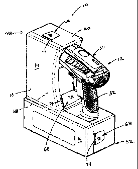
With reference now to the drawings, Figs. 1-8 and
16-20 depict an example case 10 for a power tool 12. The
case 10 has an "L-shape", with an upper vertical leg 14 and
a lower horizontal leg 16. The case 10 includes a first
casing section 18 and a second casing section 20. Openings
22, 24 are provided in the case 10 for accepting the ends
26, 28 of a power tool 12. The main body 30 of the power
tool 12 is exposed to the exterior while the ends 26, 28 of
the power tool 12 are captured within the case 10. The
handle 32 of the power tool 12 serves as a handle for the
case 10.
The first casing section 18 is a cover member and
the second casing section 20 is a base member. The cover
4a
CA 02507792 2007-09-13
31013-5
member 18 and base member 20 are coupled together along a
common hinge line 34 to form a case 10 having an interior.
In the depicted embodiment, a
4b
CA 02507792 2005-05-17 plurality of hinges 36 are disposed along the casing
hinge line 34 in the form of living hinges.
Alternatively, mechar-ical hinges that are attached to the casing sections 18,
20 may be
utilized, or other known hinges.
The interior of the case 10 includes a cavity 38 that is defined between the
inner
surface 40 of the first casing section 18 and the inner surface 42 of the
second casing section
20. The interior of each casing section includes a plurality of individual
recesses 44 thtat are
separated by ribs 46, shown best in Figs. 16 and 17. The ribs 46 help to
strengthen the casing
sections 18, 20. The recesses 46 are configured to allow the case 10 to mate
with the first
and second ends 26, 28 of a power tool 12. In the depicted embodiment, a
cordless hand-
lneld power drill is deseribed. Other types of tools may be utilized with the
example case 10,
such as a driver, a polisher, a reciprocating saw, and other known power
tools. Cordless and
corded power tools may derive a benofit from the example case 10. The cordless
dri11 is
depicted herein as an example of one use of the storage case 10. As is
evident, different
configurations of cases can be manufactured for different power tools,
according to the
example described herein.
The individual recesses 44 that are formed on the interior of the casing
sections 18, 20
are used to capture part of the power tool 12 between the first and second
casing sections 18,
20, as will be discussed in greater detail below. The recesses 44 may also be
utilized for
storing accessories for use with the power tool 12, such as a charger for a
cordless power
tool, screw and drill bits, power cords, covers, tool kits or trays, and other
accessories as
known by those of skill in the art.
As shown in Fig. 16, the base member 20 has a depth and the covex membcr 18
has a
depth. In the depiCted embodiment, the base member 20 has a depth that is
greater than the
depth of the cover member 18. As a result, the base member 20 is configured to
accept a
greater portion of the power tool 12 in its interior than is the cover member
18. In alternative
embodiments that are not shown, the cover member 18 and base member 20 may be
approximately the same depth, or the cover member 18 may be deeper than, the
base member
20. The size and configuration of the first and second casing sections 18, 20
are dependent
upon the particular application.
Referring to Figs. 6 and 7, the storage case 10 has a first opening 22 for
capturÃng a
first end 26 of the power tool 12 and a second opening 24 for capttu'ing a
second end 28 of
C1.1-1298901v 1 5
_.. ~ ,..
-.--.. - CA 02507792 2005-05-17
the power tool 12. In the case of a cordless drill 12, the first opening 22 is
defined near the
top end 48 of the case 10 for coupling with the output end 50 of the drill 12
and the second
opening 24 is defined near the bottom end 52 of the case 10 for coupling with
the battery
pack 54 of the drill 12. Other power tools may require different positions for
the openings,
the example ease ] 0 not being limited to a particular location for the
opeiiings.
As depicted in Figs, 6, 7, 19 and 20, the first opening 22 has a size to allow
the aollar
56 and chuck 58 of the drill 12 to enter the interior of the base member 20.
The first opening
22 includes an outer aperture 60 on the base member 20 that surrourids a
portion of the collar
56 of the drill 12 and an inner capture rib 62 on the base member 20 that is
positioned
between the chuck 58 and the collar 56. The inner capture rib 62 is positioned
inside the
base member 20, is formed integrally as one of the interior ribs 46 in the
cavity 38 of the case
10, and partially surrounds the drill 12 between the collar 56 and the chuck
58. Both the
inner capture rib 62 and the outer aperture 60 are seniicircular in shape. In
addition, part of
the first opening 22 is formed through the cover member 18, in the form of a
semi-circular
cut out 64 on the edge of the cover member 18. The cut out 64 is adjacent the
outer apezture
60 on the base member 20 when the cover and base members 18, 20 are folded
together in a
closed position. The semi-circular cut out 64 on the cover member 18 mates
with the semi-
circular outer aperture 60 on the base member 20 to provide an opening 22 that
is sized to
accept the entire collar 56 of the cordless drill 12.
The second opening 24 has a size to accommodate the base of the handle portion
32
of the power tool 12, at a point where the battery pack 54 mates with the
handle portion 32.
The second opening 24 is semi-circular and is positioned above a recess within
the interior of
the base member 20 that is sized to accept the battery pack 54. The first and
second openings
22, 24 are configured to capture the fmt and second ends 26, 28 of the power
tool 12 within
the case 10. When the cover member 18 is folded onto the base member 20 to
close the case
10, t1tG power tool 12 is fixedly held within the case 10 at its ends 26, 28
and the handle
portion 32 and part of the rnain body 30 of the power too112 extend from the
case 10. The
handle 32 of the power tool 12 serves as a handle for the case 10.
The disclosed example case 10 depicts the cordless drill 12 as being captured
at
certain positions on the drill 12. The case 10 could be altered in size and
cor+figuration to
capture the coralless dri1112 at other locations on the tool 12. For instance,
the dri1112 could
CLI 129fi9o1v1 6
. .~v.~...w.. m _.._ . ~ ....... _
CA 02507792 2005-05-17 .., .._,
be captured at a point on its main body 30 instead of around its collar 56. As
is evident,
variations of the disclosed example are possible based upon the teachings
provided herein.
The first and second casing sections 18, 20 may include a lip 66 around the
peripheral
edges of each section. The lip 66 may be configured to mate with a
complementary lip 66 on
the opposing casing section.
VVhen the case 10 is closed so that the cover member 18 is positioned on the
base
member 20, the casing sections 1$, 20 may be latched together via latching
components 68.
The latching components 68 include a movable latch portion 70 and a fixed
catch 72. The
movable latch portion 70 is in the form of an elongated member that extends in
length from
one casing section to the adjoining casing section. In the depicted
err+bodiment, the latch
portion 70 is attached to the base member 20 and the catch 72 is attached to
the cover
member 18. The latch portion 70 includes a lip 74 that mates with the catch 72
to maintain
the case 10 in a closed and locked position when the latch portion 70 is mated
with the
corresponding cateh 72. As shown in Fig. 6, three latching components 68 are
provided and
are spaced relative to one anoCher. A first latch is provided along an upper
wall of the case
10, a second latch is provided at an intermediate position on the side wall of
the case 10, and
a third latch is provided at a lower position on the side wall of the case 10.
Each latch portion 70 is attached to the cover member 18 via a hinge 76 a-nd
the each
catch is attached to the base member 20. In the depicted embodiment, the hinge
76 is a living
hinge, although alternative types of hinges may be utilized to couple the
latch portions 70 to
the cover member 18. Fewer or greater latch portions 70 may be utilized, if
desired. In
addition, the latch portion 70 may alterna.tively be positioned on the base
member 20, with
the corresponding catch 72 being positioned on the cover member ].8. As shown,
the latch
portion 70 and corresponding catch 72 are preferably aligned with one another
in order to
mate with one another when the latch portion 70 is in a contact with the catch
72. The
latching components 68 may be integrally formed with the casing sections 18,
20, or may be
attached via any known attachmen.t rnechanism.
The latch portions 70 may all be the same size, or may be different si2es. In
the
depicted ernbodiment, the intermediate latch portion 70 has a length that is
greater than the
length of the upper and lower latch portions 70. The larger latch portion 70
provides greater
latching strength than the smaller latch portions 70. In the depicted
embodiment, it was
CLI-1298901 vl 7
CA 02507792 2005-05-17
preferred that the intermediate latch portion 70 be stronger than the other
latch portions,
although the intermediate latch portion 70 could be the same size as the other
latching
portlons.
Referring to Figs. 16-17 and 20, the interior recesses 44 may be configured to
mate
with a storage orgainizer tray 80. In the dcpicted example, the base member 20
includes
opposcd channels or slots 78 that are positioned on inner ribs 46 of the base
member 20. The
opposed channels 78 are configured to mate with a storage tray 80 at a top and
a bottom end
of the tray. The tray 80 has ends 82 that slide into the channels 78 and the
channels 78 hold
the tray 80 in position within the base member 20 when installed.
The interior recesses 44 of the cover and base members 18, 20 may be
configured in
any known manner to accept items for storage. For example, coupling elements,
such as
menibers F'or coupling drill bits or screw bits may be attached or molded into
the inner
surfaces of the base and cover members 20, 18, Individual compartments (not
shown) with
or without covers may be formed within the recesses 44 of the base and cover
members 20,
18. Lasbes or other connectors (not shown) may be provided. Other alternatives
may also be
utilized for storing accessories in the interior cavity 38 of the case 10, the
options not being
limited to those depicted in the instant example.
The base member 20, cover member 18, latches 70 and catches 72, in one
embodiment, are made of polypropylene (-'PP") and are integrally formed during
the molding
process. Other plastic materials may be alternatively used. Materials other
than plastic may
alternatively be used. The base member 20 and cover member 18 maybe
manufactured
using an insert molding method, or via any known manufacturing method.
Figures 9-12 depict an example insert storage organizer tray 80 that may be
utilized
for storing accessories, such as drill bits or other power tool accessories.
The tray includes a
plate 86 with a plurality of coupling elcments 84 positioned on the plate 86.
The coupling
elements 84 extend outwardly from a surface of the plate 86 and are configured
to couple
tools and accessories to the plate 86.
The plate 86 includes a first half 88 and a second half 90, with a bridge 92
positioned
betwecn the first and second halves 88, 90. In the depicted embodiment, the
profile ofthe
plate 86 is "H-shaped," with the bridge 92 being formed as the center of the
"H-shape." The
bridge 92 includes a hinge line 94 and the plate 86 is conflgured to bend
along the hinge line
CLt-1 a989p1 vl 8
CA 02507792 2005-05-17
94 so that the first and second halves 88, 90 fold on top of one another. The
plate 86 has a
reduced cross-section along the hinge line 94. The folding storage tray 80
allows for greater
storage capacity while allowing the user to more easily access the components
attached to the
coupling elements 84 when the tray 80 is in use and not in storage.
Referring to Fig. 9, the plate 86 is a substantially flat member, although a
non-flat
member could be utilized. The coupling elements 84 are positioned on an outer
side 96 of
the plate 86. The coupling elements 84 includes a plurality of fasteners for
coupling various
accessories to the plate 86. Such accessories include dri.ll bits, screw bits,
screws, nails, and
other types of tools as known by those of ski.ll in the art. The coupling
alements 84 may be
positioned directly on the flat surface of the plate 86, or may be positioned
on raised
platforms 98 that are defined on the plate 86. By positioning the coupling
elements 84 ou a
single side of the plate 86, the plate 86 may be folded in half and the inner
sides 100 may be
positioned directly against one another to provide the smallest possible width
for the tray 80.
In addition, the tray 80 may be folded flat because the flat inner surfaces
100 abut one
another when the plate 86 is foldecL This is useful for storage purposes,
since trays 80 of this
sort are often installed in tight fitting recesses 44 within cases, as
discussed a.bove in
connection with the storage case 10.
Alternatively, although not shown, the coupling elernents 84 niay be
positioned on
both the inner and outer sides 100, 96 of the plate 86. When the coupling
elements 84 are
positioned on the inner sides of the plate 86, care must be taken to ensure
that the tray 80 can
properly fold in half and that accessories do not bind against each other when
the plate 86 is
folded in half for storage. In this case, the user would be required to flip
the tray 80 from one
side to the other to access all the accessories.
The plate 86 includes outwardly extending shoulders 102 that extend
perpendicularly
from the plate 86, near the side edge 82. As-discussed above, the inner side
100 of the plate
86 is flat while the outer side 96 of the plate 86 includes outwardly
extending coupling
elements 84. The shoulders 102 are spaced from the side edge 82 so that a
small section of
the flat plate 86 extends outwardly from the position of the shoulders 102.
The shoulders
102 have a height similar to the height of the coupling elements 84 and may
provide
protection to the elements from damage. When the plate 86 is folded in half ,
as shown in
Fi,gs. 13 and 14, the shoulders 102 and flat plate 86 form an "H"-shaped cross-
section with
CLt-iZVS9atv1 ~
CA 02507792 2005-05-17
protrusions 104 that extend outwardly from the sides of the "H" shape and with
the coupling
elements 84 extending outwardly from the flat plate surfaces. As shown in Fig.
16, the
protrusions 104 are utilized to cauple'with the opposed channels or slots 78
that are
positioned on the interior of one of the recesses 44 of the base member 20.
The protrusions
104 txre shaped to fit into the channels or slots 78 and the tray 80 may be
slid into the
channels or slots 78.
The bridge 92 includes a hinge 106 in the form of a living hinge that is
molded into
the plate 86. The living hinge is provided by the area of reduced cross-
section on the bridge
92. Other types of hinges, such as rnechanical hinges, may alternatively be
used. In
addition, the bridge 92 includes several ridges 108 that extend outwardly when
the plate 86 is
folded in half. When folded in half, the bridge 92 forms a tab-like structure
110 that extends
outwardly from the side of the storage tray 80. The ridges 108 on the tab-like
structure 110
may be useful to the user in inserting and withdrawing the tray 80 from a
storage position
within a storage case 10, as shown in Fig. 17. The ridges 108 provide a
gripping surface for
the user.
As shown in Fig. 9, indicia 112 such as stamp art or illustrations may be
positioned
on the surface of the plate 86. The indicia 112 is useful to the user in
identifying the types of
accessories that are stored on the tray 80, such as bits or other patts.
Irndieia 112 also
provides a helpful reminder to the user when attemptirtg to reinsert
aeGessories that have been
removed from the tray 80.
The above-described tray 80 and storage case 10 are convenient for the user
and
provide portability in carrying a power too112 and associated accessories as
one package.
Because part of the power tool 12 is positioned outside the case 10, more room
for storage is
provided in the case 10. The case 10 includes the removable storage tray 80
and includes
room for carrying an extra battery pack and charger.
In one embodiment, the insert tray 80 may be made of a Polypropylene ("PP")
material and may be manufacturad using an injection moldii g process. Other
types of
materials rnay be utilized for the insert tray 80. Other types of
manufacturing parocesses may
be utilized in manufacturiu.g the tray 80. The coupling elements 84 may be
integrally formed
with the plate 86 during the manufacturing process, or maybe attached to the
plate 86 using
any known technique.
Cla-12989o1v1 10
CA 02507792 2005-05-17 ~~=^ ==
While various features of the claimed embodiments are presented above, it
should be
understood that the features may be used singly or in any combination thereof.
Therefore, the
claimed embodiments are not to be limited to only the specific embodiments
depicted herein.
Further, it should be understood that variations and modifications may occur
to those
skilled in the art to w'hich the claimed embodiments pertains. The embodiments
described
herein are exemplary. The disclosure may enable those skilled in the art to
make and use
embodiments having alternative elements that likewise correspond to the
elements recited in
the claims. The intended scope may thus include other embodiments that do not
dit`fer or that
insubstantially differ from the literal language of the claims. The scope o f
the example
embodiments is accordingly defined as set forth in the appended claims.