Sélection de la langue

Search

Sommaire du brevet 2508583 

Énoncé de désistement de responsabilité concernant l'information provenant de tiers

Une partie des informations de ce site Web a été fournie par des sources externes. Le gouvernement du Canada n'assume aucune responsabilité concernant la précision, l'actualité ou la fiabilité des informations fournies par les sources externes. Les utilisateurs qui désirent employer cette information devraient consulter directement la source des informations. Le contenu fourni par les sources externes n'est pas assujetti aux exigences sur les langues officielles, la protection des renseignements personnels et l'accessibilité.

Disponibilité de l'Abrégé et des Revendications

L'apparition de différences dans le texte et l'image des Revendications et de l'Abrégé dépend du moment auquel le document est publié. Les textes des Revendications et de l'Abrégé sont affichés :

  • lorsque la demande peut être examinée par le public;
  • lorsque le brevet est émis (délivrance).
(12) Brevet: (11) CA 2508583
(54) Titre français: DISPOSITIF DE MESURE ET/OU D'ECHANTILLONNAGE DE METAUX EN FUSION
(54) Titre anglais: DEVICE FOR PERFORMING MEASUREMENTS AND/OR TAKING SAMPLES IN MOLTEN METALS
Statut: Périmé et au-delà du délai pour l’annulation
Données bibliographiques
(51) Classification internationale des brevets (CIB):
  • G01N 01/10 (2006.01)
  • G01N 01/12 (2006.01)
(72) Inventeurs :
  • NEYENS, GUIDO JACOBUS (Etats-Unis d'Amérique)
  • BELL, SHAUN ANDREW (Etats-Unis d'Amérique)
(73) Titulaires :
  • HERAEUS ELECTRO-NITE INTERNATIONAL N.V.
(71) Demandeurs :
  • HERAEUS ELECTRO-NITE INTERNATIONAL N.V. (Belgique)
(74) Agent: MACRAE & CO.
(74) Co-agent:
(45) Délivré: 2013-10-15
(22) Date de dépôt: 2005-05-30
(41) Mise à la disponibilité du public: 2005-12-16
Requête d'examen: 2010-02-23
Licence disponible: S.O.
Cédé au domaine public: S.O.
(25) Langue des documents déposés: Anglais

Traité de coopération en matière de brevets (PCT): Non

(30) Données de priorité de la demande:
Numéro de la demande Pays / territoire Date
10 2004 028 789.9 (Allemagne) 2004-06-16

Abrégés

Abrégé français

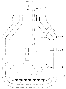
Un dispositif permet de faire des mesures ou de l'échantillonnage de métaux en fusion doté d'une lance secondaire, ayant un corps de lance secondaire, sur l'extrémité duquel un porte-lance est disposé pour recevoir une sonde d'immersion et le corps de lance secondaire est relié de manière amovible au porte-lance et/ou le porte-lance comporte plusieurs pièces qui sont mobiles les unes par rapport aux autres.


Abrégé anglais

Device for performing measurements and/or taking samples in molten metals with a sublance, which has a sublance body, on whose one end a lance holder is arranged for receiving an immersion probe, and the sublance body is movably connected to the lance holder and/or the lance holder has several parts relatively movable to each other.

Revendications

Note : Les revendications sont présentées dans la langue officielle dans laquelle elles ont été soumises.


WHAT IS CLAIMED IS:
1. A device for at least one of performing measurements and taking
samples in molten metals, comprising
a sublance having a sublance body,
a lance holder arranged on one end of the sublance body for receiving an
immersion probe,
a contact piece arranged on the lance holder for making contact with
signal lines for the immersion probe,
wherein at least one of (a) the sublance body is movably connected to
the lance holder and (b) the lance holder has several parts movable relative
to
each other, such that the contact piece is arranged to be movable relative to
the
sublance body, wherein at least one of the sublance body with the lance holder
and the parts of the lance holder is movable in at least one of an axial or
radial
direction, and wherein the axial movement and the radial movement are
realized by pairs of connection parts that are different from each other.
2. The device according to claim 1, wherein the movement is realized by
elastic parts arranged between rigid parts.
3. The device according to claim 2, wherein the elastic parts are formed as
coil springs or elastic rings.
7

Description

Note : Les descriptions sont présentées dans la langue officielle dans laquelle elles ont été soumises.


CA 02508583 2005-05-30
Device for performing measurements and/or taking samples in molten
metals
The invention relates to a device for performing measurements and/or taking
samples in molten metals with a sublance, which has a sublance body, on
whose one end a lance holder is arranged for receiving an immersion probe.
Such devices are sufficiently well known to those skilled in the art. They are
used for measurements or taking samples in molten metals. Such sampling is
partially automated, wherein a sublance is dipped into a melt container, after
which the immersion probe arranged on the sublance is discarded, because it
is used up, and a new immersion probe is placed on the sublance. In order to
automate this procedure, the sublance must be able to be positioned exactly
over a probe storage container. In practice, however, it has been shown that,
due to the loads exerted on a sublance during use, these sublances become
slightly deformed, so that the lance holder can no longer be placed exactly
over an immersion probe and the probe cannot be received without prob-
lems. The immersion probes placed on the sublances do not have the same
exact length. In particular, the contact part housed in the carrier tube
cannot
always be reached at the same depth by the counter contact in the sublance.
As a result, splashes of the molten metal frequently settle onto parts of the
sublance, which must remain free for forming the contact, so that trouble-
free placement of the immersion probes is impossible. This can disrupt the
entire steel making process.
Sublances are known, for example, from EP 69 433. Here, an attempt is
made to counteract the deformation of the sublance during the operation by
rotating the sublance. The arrangement and function of sublances is further
7405689 vl 1

CA 02508583 2005-05-30
described in DE 43 06 332 A1. Here, the exchanging procedure of the
sample probes is also disclosed. Another sublance is known from EP 143
498 A2. The sublance described here has a seal, for example a rubber ring, at
connection points, which prevents liquid metal from being able to penetrate
into the mechanism.
The invention is based on the problem of improving the known sublances
and especially enhancing the fail-safe means in automatic operation.
The problem is solved for the invention characterized above in that on the
lance holder a contact piece is arranged for making contact with signal lines
of the immersion probe, furthermore in that the sublance body is movably
connected to the lance holder or to a part thereof and/or in that the lance
holder has several parts relatively movable to each other, whereby the
contact piece is arranged to be movable relative to the sublance, especially
to
the sublance body. The sublance is pushed tight onto the upper part of the
lance holder and is preferably held so that it cannot move. The lower part of
the lance holder is movable with the contact piece, so that the probe can be
brought into contact with the contact piece. The lance holding can thereby
adapt to the already set sensor, so that a sufficient contact is possible even
for slightly deformed components or even when molten metal adheres to the
sublance. Different insertion depths of the sublance into the carrier tube of
the immersion probe are likewise compensated in this manner. Preferably,
the sublance body with the lance holder and/or the parts of the lance holder
are arranged to be movable in the axial direction and/or in the radial
direction. Furthermore, it is advantageous when the axial movement and the
radial movement are realized by pairs of connection parts that are different
2

CA 02508583 2012-12-07
from each other, in order to obtain the highest possible flexibility and
adaptability. Especially for adhesion of molten metal on the sublance or for
differently arranged contact parts of the immersion probe, an axial move-
ment is important, in order to guarantee the correct contact with the immer-
sion probe. In particular, it is advantageous when the movement is realized
by elastic parts arranged between rigid parts, wherein the elastic parts can
be
formed as a spring, for example as a coil spring, or as an elastic ring.
Furthermore, it is useful if a part of the lance holder has a receiving hole,
in
which a peg of a second part of the lance holder can move in the axial
o direction, wherein a coil spring is arranged between the first and the
second
parts of the lance holder. For this purpose, it is advantageous if the coil
spring is arranged between a stopping surface arranged at the front end or on
the peripheral surface of the peg and a second stopping surface arranged at
or in the hole. The components guaranteeing the movement are thereby
protected themselves.
It is useful if a part of the lance holder has a receiving hole, in which a
peg
of a second part of the lance holder is movable in the radial direction,
wherein at least one elastic ring is arranged between the first and the second
parts of the lance holder. The elastic ring can be arranged advantageously in
the radial direction between the two parts of the lance holder.
According to one aspect of the present invention there is provided a device
for
at least one of performing measurements and taking samples in molten metals,
comprising a sublance having a sublance body, a lance holder arranged on one
end of the sublance body for receiving an immersion probe, a contact piece
3

CA 02508583 2012-12-07
P
arranged on the lance holder for making contact with signal lines for the
immersion probe, wherein at least one of (a) the sublance body is movably
connected to the lance holder and (b) the lance holder has several parts
movable relative to each other, such that the contact piece is arranged to be
movable relative to the sublance body, wherein at least one of the sublance
body with the lance holder and the parts of the lance holder is movable in at
least one of an axial or radial direction, and wherein the axial movement and
the radial movement are realized by pairs of connection parts that are
different
from each other.
An embodiment of the invention is described below with reference to a
drawing. Shown in the drawing are:
Fig. 1 a converter furnace with a sublance,
3a

CA 02508583 2005-05-30
Fig. 2 a sublance with lance holder and immersion probe, and
Fig. 3 a lance holder in detail.
In the converter furnace shown in Fig. 1 a blowing lance 1 is arranged,
which blows oxygen into the molten slag 2 or molten steel 3. Next to this
lance a sublance 4 with an immersion probe 5 is arranged. The sublance 4
travels from above into the converter furnace until the immersion probe 5 is
immersed in the molten steel 3. After the measurement, the sublance is
pulled up; the immersion probe 5 is destroyed. If the probe is designed as a
measurement probe, then the measurement is performed during the immer-
sion in the molten steel 3. A sample chamber arranged in the immersion
probe 5 was filled while in the molten steel 3. The sample chamber is
removed from the discarded immersion probe 5, and the sample can be
is analyzed. For the next measurement, another immersion probe 5 is taken
from a storage container, usually mechanically mounted on the sublance 4,
and inserted into the converter furnace for the measurement.
Fig. 2 shows the immersion probe 5 arranged at the lower end of the
sublance 4. The immersion probe 5 has an immersion end, which is pro-
tected from the slag layer 2 lying on the molten steel 3 by a cap 6, which
exposes the sensor or the sample chamber only after being immersed in the
molten steel 3. The immersion probe 5 is fixed to the sublance 4 by means of
the lance holder. The signal lines of the immersion probe 5 are contacted by
a contact piece 7 arranged on the lance holder, so that the measurement
signals can be led back through the sublance 4 to an analysis unit.
4

CA 02508583 2005-05-30
In Fig. 3 the lance holder is shown. The lance holder is a reusable part of
the
sublance 4. It is used for holding the immersion probe 5 and as a contact
connection with the immersion probe 5. The lance holder is connected to the
water-cooled part of the sublance 4. The water cooling is not explained in
more detail in the Figures. It is sufficiently well known from the prior art
(for example, EP 69 433). The lance holder is arranged with its upper part 8
rigidly in the sublance 4 and with its lower part, beginning approximately at
the separating line 9, in the immersion probe 5. In this way, the contact
piece
7 guarantees the electrical contact with the signal lines of the immersion
probe 5. The conductance of the electrical signals and their transmission to a
measurement or analysis station take place through the lance cable 10, which
is arranged at the upper end of the lance holder and which passes through the
sublance 4. A rubber ring 11 is arranged in the upper region of the lance
holder. The rubber ring 11 enables the lower part of the lance holder to move
in both the radial direction and the axial direction relative to the upper
part 8.
The rubber ring 11 is held against a stop 17 by a screw 16. The screw 16 has
a through hole 18 in the axial direction, which expands conically in the
direction towards the contact piece 7. The upper part 8 of the sublance 4 is
thereby movable relative to the lower part in the radial direction and also
slightly in the axial direction. Instead of a rubber ring 11, a metal spring,
for
example a coil spring, can also be used. The lower part of the lance holder
with the contact piece 7 has a sealing sleeve 12, into which a guide tube 13
projects. A coil spring 14 is arranged in the longitudinal direction between
the guide tube 13 and an inner stopping surface of the sealing sleeve 12.
Movement of the contact piece 7 with the sealing sleeve 12 along the guide
tube 13 is thereby guaranteed. This movement always ensures a secure
contact between the signal lines of the immersion sensor 5 and the contact
5

CA 02508583 2012-12-07
piece 7, even with different lengths of the various immersion sensors 5,
which are mounted on the lance holder. A secure contact is then guaranteed
even if foreign matter, such as molten metal or slag, has become fixed on the
lance holder. This can occur in the upper part of the lance holder, where the
sublance 4 and the immersion probe 5 contact each other. Even in such a
case of contamination, a reliable contact between the contact piece 7 and the
signal lines of the immersion probe 5 is guaranteed by the spring 14. The
spring 14 preferably has a spring tension that is greater than the attachment
force of the contact piece 7 on the so-called connector within the immersion
probe 5, with whose help the signal lines make contact with the contact
piece. Within the guide tube 13 coupling elements 15 can be provided, by
which the lance cable 10 is connected to the contact piece 7. In the manner
shown, the contact piece 7 is arranged to be movable both in the longitudinal
and the radial directions relative to the sublance 4, and therefore can then
be
connected to the signal lines of the immersion probe, even if the lower end
of the sublance 4 carrying the lance holder is slightly bent. A secure,
mechanical holding of the immersion probe 5 is possible as well in practi-
cally every conceivable case.
The scope of the claims should not be limited by the preferred embodiments set
forth in the examples, but should be given the broadest interpretation
consistent
with the description as a whole.
6

Dessin représentatif
Une figure unique qui représente un dessin illustrant l'invention.
États administratifs

2024-08-01 : Dans le cadre de la transition vers les Brevets de nouvelle génération (BNG), la base de données sur les brevets canadiens (BDBC) contient désormais un Historique d'événement plus détaillé, qui reproduit le Journal des événements de notre nouvelle solution interne.

Veuillez noter que les événements débutant par « Inactive : » se réfèrent à des événements qui ne sont plus utilisés dans notre nouvelle solution interne.

Pour une meilleure compréhension de l'état de la demande ou brevet qui figure sur cette page, la rubrique Mise en garde , et les descriptions de Brevet , Historique d'événement , Taxes périodiques et Historique des paiements devraient être consultées.

Historique d'événement

Description Date
Le délai pour l'annulation est expiré 2019-05-30
Inactive : CIB expirée 2019-01-01
Lettre envoyée 2018-05-30
Accordé par délivrance 2013-10-15
Inactive : Page couverture publiée 2013-10-14
Inactive : Taxe finale reçue 2013-08-07
Préoctroi 2013-08-07
Un avis d'acceptation est envoyé 2013-07-23
Lettre envoyée 2013-07-23
Un avis d'acceptation est envoyé 2013-07-23
Inactive : Approuvée aux fins d'acceptation (AFA) 2013-07-15
Modification reçue - modification volontaire 2012-12-07
Inactive : Dem. de l'examinateur par.30(2) Règles 2012-09-11
Modification reçue - modification volontaire 2010-04-20
Lettre envoyée 2010-03-15
Exigences pour une requête d'examen - jugée conforme 2010-02-23
Toutes les exigences pour l'examen - jugée conforme 2010-02-23
Requête d'examen reçue 2010-02-23
Demande publiée (accessible au public) 2005-12-16
Inactive : Page couverture publiée 2005-12-15
Inactive : CIB en 1re position 2005-09-22
Inactive : CIB attribuée 2005-09-22
Lettre envoyée 2005-09-12
Inactive : Transfert individuel 2005-07-21
Inactive : Lettre de courtoisie - Preuve 2005-07-19
Inactive : Certificat de dépôt - Sans RE (Anglais) 2005-07-12
Demande reçue - nationale ordinaire 2005-07-11

Historique d'abandonnement

Il n'y a pas d'historique d'abandonnement

Taxes périodiques

Le dernier paiement a été reçu le 2013-05-14

Avis : Si le paiement en totalité n'a pas été reçu au plus tard à la date indiquée, une taxe supplémentaire peut être imposée, soit une des taxes suivantes :

  • taxe de rétablissement ;
  • taxe pour paiement en souffrance ; ou
  • taxe additionnelle pour le renversement d'une péremption réputée.

Les taxes sur les brevets sont ajustées au 1er janvier de chaque année. Les montants ci-dessus sont les montants actuels s'ils sont reçus au plus tard le 31 décembre de l'année en cours.
Veuillez vous référer à la page web des taxes sur les brevets de l'OPIC pour voir tous les montants actuels des taxes.

Historique des taxes

Type de taxes Anniversaire Échéance Date payée
Taxe pour le dépôt - générale 2005-05-30
Enregistrement d'un document 2005-07-21
TM (demande, 2e anniv.) - générale 02 2007-05-30 2007-05-14
TM (demande, 3e anniv.) - générale 03 2008-05-30 2008-05-13
TM (demande, 4e anniv.) - générale 04 2009-06-01 2009-05-14
Requête d'examen - générale 2010-02-23
TM (demande, 5e anniv.) - générale 05 2010-05-31 2010-05-13
TM (demande, 6e anniv.) - générale 06 2011-05-30 2011-05-12
TM (demande, 7e anniv.) - générale 07 2012-05-30 2012-05-14
TM (demande, 8e anniv.) - générale 08 2013-05-30 2013-05-14
Taxe finale - générale 2013-08-07
TM (brevet, 9e anniv.) - générale 2014-05-30 2014-05-19
TM (brevet, 10e anniv.) - générale 2015-06-01 2015-05-19
TM (brevet, 11e anniv.) - générale 2016-05-30 2016-05-17
TM (brevet, 12e anniv.) - générale 2017-05-30 2017-05-24
Titulaires au dossier

Les titulaires actuels et antérieures au dossier sont affichés en ordre alphabétique.

Titulaires actuels au dossier
HERAEUS ELECTRO-NITE INTERNATIONAL N.V.
Titulaires antérieures au dossier
GUIDO JACOBUS NEYENS
SHAUN ANDREW BELL
Les propriétaires antérieurs qui ne figurent pas dans la liste des « Propriétaires au dossier » apparaîtront dans d'autres documents au dossier.
Documents

Pour visionner les fichiers sélectionnés, entrer le code reCAPTCHA :


Pour visualiser une image, cliquer sur un lien dans la colonne description du document. Pour télécharger l'image (les images), cliquer l'une ou plusieurs cases à cocher dans la première colonne et ensuite cliquer sur le bouton "Télécharger sélection en format PDF (archive Zip)" ou le bouton "Télécharger sélection (en un fichier PDF fusionné)".

Liste des documents de brevet publiés et non publiés sur la BDBC .

Si vous avez des difficultés à accéder au contenu, veuillez communiquer avec le Centre de services à la clientèle au 1-866-997-1936, ou envoyer un courriel au Centre de service à la clientèle de l'OPIC.


Description du
Document 
Date
(aaaa-mm-jj) 
Nombre de pages   Taille de l'image (Ko) 
Revendications 2012-12-06 1 29
Description 2005-05-29 6 266
Abrégé 2005-05-29 1 10
Revendications 2005-05-29 2 59
Dessins 2005-05-29 3 53
Dessin représentatif 2005-11-17 1 21
Description 2012-12-06 7 297
Certificat de dépôt (anglais) 2005-07-11 1 158
Courtoisie - Certificat d'enregistrement (document(s) connexe(s)) 2005-09-11 1 104
Rappel de taxe de maintien due 2007-01-30 1 111
Rappel - requête d'examen 2010-02-01 1 118
Accusé de réception de la requête d'examen 2010-03-14 1 177
Avis du commissaire - Demande jugée acceptable 2013-07-22 1 163
Avis concernant la taxe de maintien 2018-07-10 1 180
Correspondance 2005-07-11 1 26
Correspondance 2013-08-06 1 29