Note : Les descriptions sont présentées dans la langue officielle dans laquelle elles ont été soumises.
CA 02515233 2005-08-04
WO 2004/072621 PCT/US2003/003564
DETERMINATION OF AMOUNT OF PROPPANT ADDED TO A
FRACTURE FLUID USING A CORIOLIS FLOW METER
Background of the Invention
1. Field of the Invention
The invention is related to the field of measurement systems, and in
particular, to a
system and method that use measurements from a Coriolis flow meter to
determine the
amount of proppant in a fracture fluid.
2. Staternent of the Problenz
Oil, gas, and other resources under ground are obtained by drilling a well.
The well
is drilled to a certain depth and cased in cement. The well extends through
multiple zones
in the ground that a drilling crew may wish to tap. To tap into a certain
zone, the drilling
crew fractures a portion of the casing in the desired zone. The fracturing
process used could
be hydraulic fracturing, pneumatic fracturing, or another type of fracturing.
With the casing
fractured, the drilling crew then pumps a fracture fluid into the fracture to
keep the fracture
open. The fracture fluid holds the fracture open while still being permeable.
This enables
the oil and gas to more easily flow through the fracture into the well-bore.
The fracture fluid is made up of a base fluid and a proppant. To make the base
fluid,
a Guar gum is added to water in a large tank. A mixer within the tank
continually mixes the
Guar guin and the water together to make the base fluid. When mixed, the base
fluid has
the consistency somewhat like molasses.
A proppant, such as sand, is then added to the base fluid in the tank to make
the
fracture fluid. The amount of sand added depends on soil type, soil
conditions, and other
factors. The mixer in the tank mixes the base fluid and the sand together to
make the
fracture fluid. The fracture fluid is then pumped into the well-bore to help
keep the fracture
open. The amount of the sand in the fracture fluid determines how well the
fracture fluid is
able to hold the fracture open.
Because the amount of sand in the fracture fluid is important, the drilling
crew may
want to measure the amount of sand added. This can be a difficult process
because the
fracture fluid is usually not made in a batch, but is continuously mixed. To
determine the
amount of sand in the fracture fluid, the drilling crew uses a nuclear
densitometer to
measure the density of the fracture fluid being pumped into the well-bore. A
controller
receives the density measurement from the nuclear densitometer and calculates
the amount
of sand added to the fracture fluid. The drilling crew can then adjust the
amount of sand to
1
CA 02515233 2005-08-04
WO 2004/072621 PCT/US2003/003564
a desired level. An example of a system for providing the fracture fluid is
described below
and illustrated in FIG. 1.
Unfortunately, there are problems associated with using nuclear densitometers.
For
instance, interstate and international transport of nuclear densitometers can
be a difficult
process considering the laws and regulations surrounding nuclear technology.
There are
also concerns for safe handling and transporting of the nuclear densitometers.
The
operators of the nuclear densitometers have to be certified or licensed by the
proper
regulatory agency. Such factors make nuclear densitometers undesirable to use.
Coriolis flow meters are used to measure the mass flow rate, density, and
other
information for fluids. Exemplary Coriolis flow meters are disclosed in U.S.
Pat. No.
4,109,524 of August 29, 1978, U.S. Pat. No. 4,491,025 of January 1, 1985, and
Re. 31,450
of February 11, 1982, all to J. E. Smith et al. Coriolis flow meters are
comprised of one or
more flow tubes of a straight or curved configuration. Each flow tube
configuration in a
Coriolis flow meter has a set of natural modes of vibration, which may be of a
simple
bending, twisting, torsional, or coupled type. Each flow tube is driven to
oscillate at
resonance in one of these natural modes of vibration. Fluid flows into the
flow meter from
a connected pipeline on the inlet side of the flow meter. The fluid is
directed through the
flow tube(s), and exits the flow meter through the outlet side of the flow
meter. The natural
vibration modes of the vibrating, fluid-filled system are defined in part by
the combined
mass of the flow tubes and the mass of the fluid flowing through the flow
tubes.
As fluid begins to flow through the flow tubes, Coriolis forces cause points
along
the flow tubes to have a different phase. The phase on the inlet side of the
flow tube
commonly lags the driver while the phase on the outlet side of the flow tube
leads the
driver. Pickoffs are affixed to the flow tube(s) to measure the motion of the
flow tube(s)
and generate pickoff signals that are representative of the motion of the flow
tube(s).
Meter electronics, or any other ancillary electronics or circuitry connected
to the
flow meter, receive the pickoff signals. The meter electronics processes the
pickoff signals
to determine the phase difference between the pickoff signals. The phase
difference
between two pickoff signals is proportional to the mass flow rate of the fluid
through the
flow tube(s). The meter electronics can also process one or both of the
pickoff signals to
determine the density of the fluid.
Unfortunately, Coriolis flow meters have not been used to measure the density
of a
fracture fluid. First, the fracture fluid is usually pumped down the well-bore
through a large
tube, such as an eight inch tube. Coriolis flow meters have not been built
large enough to
2
CA 02515233 2005-08-04
WO 2004/072621 PCT/US2003/003564
measure an eight inch stream. Secondly, most Coriolis flow meters have curved
flow tubes.
The erosive properties of sand through the curved flow tubes prevents the
curved-tube
Coriolis flow meter from being a viable option. The sand would damage the flow
tubes in a
matter of hours. For these reasons, Coriolis flow meters have not been used to
measure the
5' fracture fluid, and nuclear densitometers continue to be used.
Summary of the Solution
The invention helps solve the above problems with a measurement system
comprising a Coriolis flow meter and a control system. A base fluid is first
flowed through
the Coriolis flow meter. The Coriolis flow meter measures a density of the
base fluid and
transmits a base fluid density measurement to the control system. A proppant
is added to
the base fluid creating a fracture fluid. The fracture fluid is then flowed
through the
Coriolis flow meter. The Coriolis flow meter measures a density of the
fracture fluid and
transmits a fracture fluid density measurement to the control system. The
control system
determines an amount of proppant in the fracture fluid based on the base fluid
density
measurement, the fracture fluid density measurement, and a density of the
proppant.
The measurement system advantageously replaces nuclear technology with
Coriolis
technology. Coriolis flow meters can provide accurate density measurements,
while
avoiding the problems of handling and transporting radioactive sources and
instruments.
Coriolis flow meters also do not have the intrinsic safety concerns of the
nuclear
densitometer.
In another example of the invention, the Coriolis flow meter is configured to
receive
a slip stream of material. To provide the slip stream, the measurement system
further
comprises a first tube and a second tube. The first tube has a first end
configured to connect
to an input of the Coriolis flow meter and has a second end configured to
connect to a
discharge of a tank. The second tube has a first end configured to connect to
an output of
the Coriolis flow meter and has a second end configured to connect to a tank.
The first tube
receives a slip stream of material from the discharge of the tank. The slip
stream travels
through said first tube, through said Coriolis flow meter, through said second
tube, and back
into said tank. The slip stream advantageously provides a smaller flow to
measure, such as
a one inch flow.
Other examples of the invention may be disclosed below.
The following sets forth aspects of the invention. One aspect of the invention
comprises a measurement system comprising a Coriolis flow meter and a control
system,
said measurement system characterized by:
3
CA 02515233 2005-08-05
Prirtted910=09-2004 DESCPAMD l1S 03707747'
35010/144W
said Coriolis flow meter being configured to measure a density of a base fluid
flowing through said Coriolis flow meter to generate a base fluid density
measurement,
transmit said base fluid density measurement, receive a slip stream of a
fracture fluid to
measure a density of said fracture fluid, measure the density of the fracture
fluid flowing
through said Coriolis flow meter to generate a fracture fluid density
measurement, wherein
said fracture fluid comprises a mixture of said base fluid and a proppant, and
transmit said
fracture fluid density measurement; and
said control system being configured to receive said base fluid density
measurement and said fracture fluid density measurement, and determine an
amount of said
proppant in said fracture fluid based on said base fluid density measurement,
said fracture
fluid density measurement, and a density of said proppant.
Preferably, the Coriolis flow meter comprises a straight tube Coriolis flow
meter.
Preferably, the measurement system further comprises:
a first tube having a first end configured to connect to an input of said
Coriolis flow
meter and having a second end configured to connect to a discharge of a tank;
and
a second tube having a first end configured to connect to an output of said
Coriolis
flow meter and having a second end configured to connect to said tank;
wherein said first tube is configured to receive a slip stream of material
from said
discharge of said tank, said slip stream travels through said first tube,
through said Coriolis
flow meter, through said second tube, and back into said tank.
Preferably, the control system is configured to determine said density of said
proppant.
Preferably, the control system comprises a display system configured to
provide said
amount of said proppant to a user.
Preferably, the control system comprises an auxiliary interface configuxed to
transmit a signal representing said amount of said proppant to an auxiliary
system.
Preferably, the control system comprises a user interface configured to
receive said
density of said proppant entered by a user.
Preferably, the control system is configured to:
calculate a velocity of said fracture fluid;
determine if said velocity of said fracture fluid exceeds a threshold; and
provide an indication if said velocity of said fracture fluid exceeds said
threshold.
Preferably, the control system is configured to:
4
1 AMENDED SHEET 2004-08-27.
CA 02515233 2005-08-05
6?rinled:10-00-2a04 DESCPAMD US 0370774-7
JJV1V7 d r4rWO
calculate an average density of said base fluid based on a plurality of
density
measurements of said base fluid by said Coriolis flow meter; and
determine said amount of said proppant in said fracture fluid based on said
average
density of said base fluid, said fracture fluid density measurement, and said
density of said
proppant.
Preferably, the Coriolis flow meter is configured to measure a mass flow rate
of said
fracture fluid, and provide at least one of said mass flow rate of said
fracture fluid and a
drive gain of said Coriolis flow meter to said control system; and
said control system is configured to provide at least one of said mass flow
rate of
said fracture fluid and said drive gain of said Coriolis flow meter to a user.
Another aspect of the invention comprises a method of ineasuring an amount of
proppant in a fracture fluid, said method comprising the step of:
determining a density of said proppant;
said method characterized by the steps of:
measuring a density of a base fluid with a Coriolis flow meter to generate a
base fluid density measurement;
receiving a slip stream of a fracture fluid into said Coriolis flow meter to
measure a density of said fracture fluid;
measuring the density of the fracture fluid with said Coriolis flow meter to
generate a fracture fluid density measurement, wherein said fracture fluid
comprises a
mixture of said base fluid and a proppant; and
deterrnining an amount of said proppant in said fracture fluid based on said
base fluid density measurement, said fracture fluid density measurement, and
said density of
said proppant.
Preferably, the step of measuring a density of a fracture fluid with said
Coriolis flow
meter comprises:
measuring said density of said fracture fluid with a straight tube Coriolis
flow meter.
Preferably, the method further comprises the steps of:
connecting a first end of a first tube to an input of said Coriolis flow
meter;
connecting a second end of said first tube to a discharge of a tank;
5
;
2 AMENDED SHEET 2004-08,27
CA 02515233 2005-08-04
WO 2004/072621 PCT/US2003/003564
wherein said first tube receives a slip stream of material from said discharge
of said
tank, said slip stream travels through said first tube, through said Coriolis
flow meter,
through said second tube, and back into said tank.
Preferably, the method further comprises the step of providing said amount of
said
proppant to a user.
Preferably, the method further comprises the step of transmitting a signal
representing said amount of said proppant to an auxiliary system.
Preferably, the method further comprises the step of receiving said density of
said
proppant from a user.
Preferably, the method further comprises the steps of:
calculating a velocity of said fracture fluid;
determining if said velocity of said fracture fluid exceeds a threshold; and
providing an indication if said velocity of said fracture fluid exceeds said
threshold.
Preferably, the method further comprises the steps of:
calculating an average density of said base fluid based on a plurality of
density
measureinents of said base fluid by said Coriolis flow meter; and
determining said amount of said proppant in said fracture fluid based on said
average density of said base fluid, said fracture fluid density measurement,
and said density
of said proppant.
Preferably, the method further comprises the steps of:
measuring a mass flow rate of said fracture fluid with said Coriolis flow
meter; and
providing at least one of said mass flow rate of said fracture fluid and a
drive gain of
said Coriolis flow meter to a user.
Description of the Drawings
The same reference number represents the same element on all drawings.
FIG. 1 illustrates a system for supplying a fracture fluid to a well-bore in
the prior
art.
FIG. 2 illustrates a measurement system in an example of the invention.
FIG. 3 illustrates an example of a control system in an example of the
invention.
FIG. 4 illustrates an example of a Coriolis flow meter in an example of the
invention.
FIG. 5 is a flow chart illustrating an example operation of a measurement
system in
an example of the invention.
6
CA 02515233 2005-08-04
WO 2004/072621 PCT/US2003/003564
Detailed Description of the Invention
FIG. 1 illustrates a system for supplying a fracture fluid to a well-bore in
the prior
art to assist in understanding the invention. FIGS. 2-5 and the following
description depict
specific examples of the invention to teach those skilled in the art how to
make and use the
best mode of the invention. For the purpose of teaching inventive principles,
some
conventional aspects of the invention have been simplified or omitted. Those
skilled in the
art will appreciate variations from these examples that fall within the scope
of the invention.
Those, skilled in the art will appreciate that the features described below
can be combined in
various ways to form multiple variations of the invention. As a result, the
invention is not
limited to the specific examples described below, but only by the claims and
their
equivalents.
System for Supplying a Fracture Fluid in the Prior Art -- FIG. 1
FIG. 1 illustrates a fracture fluid system 100 for supplying a fracture fluid
102 to a
well-bore in the prior art. Fracture fluid system 100 is comprised of a
tank/mixer 110, a
recirculation tube 111, a supply tube 112, a discharge tube 118, a valve 113,
a pump 128, a
nuclear densitometer 114, and a controller 116. Discharge tube 118 is
connected to
tank/mixer 110 at one end and valve 113 at the other. Pump 128 and nuclear
densitometer
114 are connected to discharge tube 118. Recirculation tube 111 is connected
to valve 113
at one end and tank/mixer 110 at the other. Supply tube 112 is connected to
valve 113 and
is configured to transport the fracture fluid 102 to the well-bore. Valve 113
either directs a
flow of the fracture fluid 102 through recirculation tube 111 or through
supply tube 112.
Supply tube 112, recirculation tube 111, and discharge tube 118 have at least
eight inch
diameters. Controller 116 is coupled to nuclear densitometer 114.
In operation, water 120, gum 122, and sand 124 are added to tank/mixer 110.
Tank/mixer 110 mixes the water 120, the gum 122, and the sand 124 together to
make the
fracture fluid 102. The ainount of sand added to the water 120 and the gum 122
in the
fracture fluid 102 depends on the soil type, soil conditions, and other
factors. The operator
of fracture fluid system 100 uses nuclear densitometer 114 and controller 116
to measure
the amount of sand in the fracture fluid 102.
As the full stream of the fracture fluid 102 flows through discharge tube 118,
nuclear
densitometer 114 measures the density of the fracture fluid 102. Nuclear
densitometer 114
transmits the density measurement to controller 116. Controller 116 knows the
density of
the sand 124, the density of the water 120, and the density of the gum 122.
These values
may be entered into controller 116 by the operator. Controller 116 calculates
the amount of
7
CA 02515233 2005-08-04
WO 2004/072621 PCT/US2003/003564
sand in the fracture fluid 102 based on the density measurement of the
fracture fluid 102,
and the known densities of the sand 124, the water 120, and the gum 122.
Controller 116
includes a display 136. Controller 116 provides the amount of sand in the
fracture fluid 102
to the operator using display 136.
As described above, there are many problems associated with using nuclear
densitometer 114. For instance, interstate and international transport of
nuclear
densitometers can be a difficult process, safe handling and transporting of
the nuclear
densitometers is a concern, and the people operating the nuclear densitometers
have to be
certified or licensed by the proper regulatory agency. Such factors make
nuclear
densitometers undesirable to use.
Measurement System and Operation -- FIG. 2
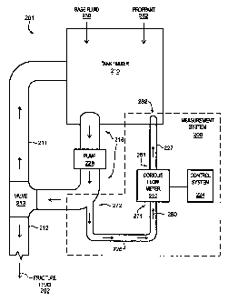
FIG. 2 illustrates a measurement system 200 in an example of the invention.
Measurement system 200 is configured to operate with a fracture fluid system
201 for
supplying a fracture fluid 202 to a well-bore (not shown). Fracture fluid
system 201 is
comprised of a tank/mixer 210, a discharge tube 218, a valve 213, a
recirculation tube 211,
a supply tube 212, a pump 228, and measurement system 200. Discharge tube 218
is
connected to tank/mixer 210 at one end and valve 213 at the other. Pump 228 is
also
connected to discharge tube 218. Recirculation tube 211 is connected to valve
213 at one
end and tank/mixer 210 at the other. Supply tube 212 is connected to valve 213
and is
configured to transport the fracture fluid 202 to the well-bore. Valve 213
either directs a
flow of material through recirculation tube 211 or through supply tube 212.
Fracture fluid
system 201 may be comprised of many other components that are not shown for
the sake of
brevity.
Measurement system 200 is comprised of a Coriolis flow meter 222 and a control
system 224. Measurement system 200 may also include tubes 226-227 that form a
slip
stream from discharge tube 218. Tubes 226-227 may be one inch rubber tubing.
Tube 226
includes ends 271 and 272. End 271 connects to an inlet end of Coriolis flow
meter 222.
End 272 connects to discharge tube 218. End 272 may connect to an elbow of
discharge
tube 218 to obtain the best results. Tube 227 includes ends 281 and 282. End
281 connects
to an outlet end of Coriolis flow meter 222 and end 282 connects to tank/mixer
210. Tube
226, Coriolis flow meter 222, and tube 227 are configured to receive a slip
stream 280 of
material. The slip stream 280 enters tube 226, and passes through tube 226,
through
Coriolis flow meter 222, through tube 227, and back into tank/mixer 210.
8
CA 02515233 2005-08-04
WO 2004/072621 PCT/US2003/003564
The following definitions may be helpful in understanding the invention. A
Coriolis
flow meter comprises any meter configured to measure a density of a material
based on the
Coriolis principle. An example of a Coriolis flow meter is a Model T- 100
straight tube
meter manufactured by Micro Motion Inc. of Boulder, Colorado. A fracture fluid
comprises
any fluid, material, or mixture used to resist crushing of a fracture in a
well-bore and
provide a permeable path. A proppant comprises any material or agent used in a
fracture
fluid to help keep the fractures open. An example of a proppant is sand. A
base fluid
comprises any material or agent mixed with a proppant to form a fracture
fluid. A tank or
tank/mixer comprises any tub or container that stores a material. A tube
comprises any
hose, tubing, line, pipe, etc.
In operation, tank/mixer 210 receives and mixes the base fluid 250. Based on
the
setting of valve 213, pump 228 circulates the base fluid 250 through discharge
tube 218 and
recirculation tube 211. Tube 226 receives a slip stream 280 of the base fluid
250. The slip
stream 280 of the base fluid 250 travels through tube 226, through Coriolis
flow meter 222,
through tube 227, and back into tank/mixer 210. With the base fluid 250
flowing through
Coriolis flow meter 222, Coriolis flow meter 222 measures a density of the
base fluid 250.
Coriolis flow meter 222 transmits a base fluid density measurement to control
system 224.
Tank/mixer 210 then receives and mixes the proppant 252 with the base fluid
250 to
make the fracture fluid 202. Based on the setting of valve 213, pump 228
circulates the
fracture fluid 202 through discharge tube 218 and recirculation tube 211. Tube
226 receives
a slip stream 280 of the fracture fluid 202. The slip stream 280 of the
fracture fluid 202
travels through tube 226, through Coriolis flow meter 222, through tube 227,
and back into
tank/mixer 210. With the fracture fluid 202 flowing through Coriolis flow
meter 222,
Coriolis flow meter 222 measures a density of the fracture fluid 202. Coriolis
flow meter
222 transmits a fracture fluid density measurement to control system 224.
Control systein 224 receives the base fluid density measurement and the
fracture
fluid density measurement. Control system 224 also receives the density of the
proppant
252. Control system 224 may receive the density of the proppant 252 from an
operator,
from a memory, or from another source. Control system 224 determines an amount
of the
proppant 252 in the fracture fluid 202 based on the base fluid density
measurement, the
fracture fluid density measurement, and the density of the proppant 252. An
operator of
fracture fluid system 201 can look at the amount of proppant 252 in the
fracture fluid 202,
as determined by control system 224, to adjust the amount of the proppant 252
added to the
9
CA 02515233 2005-08-04
WO 2004/072621 PCT/US2003/003564
fracture fluid 202. Based on this disclosure, those skilled in the art will
appreciate how to
modify existing measurement systems to make measurement system 200.
When the fracture fluid 202 has the proper amount of proppant 252, valve 213
is
switched so that the fracture fluid 202 is pumped down hole through supply
tube 212.
There may be other devices or systems connected to supply tube 212 to puinp
the fracture
fluid 202 down hole, such as a large puinp.
Control System -- FIG. 3
FIG. 3 illustrates an example of control system 224 in an exainple of the
invention.
Control system 224 comprises a display 302, a user interface 304, and an
auxiliary interface
306. An example of control system 224 is the Daniel F1oBossTM 407. Display
302 is
configured to display any relevant data to an operator. An example of display
302 is a
Liquid Crystal Display (LCD). User interface 304 is configured to allow the
operator to
enter information into control system 224. An example of user interface 304 is
a keypad.
Auxiliary interface 306 is configured to transmit information to, and receive
information
from, an auxiliary system (not shown). An example of auxiliary interface 306
is a serial
data port.
Control system 224 may also comprise a processor and a storage media. The
operation of control system 224 may be controlled by instructions that are
stored on the
storage media. The instructions can be retrieved and executed by the
processor. Some
examples of instructions are software, program code, and firmware. Some
examples of
storage media are memory devices, tape, disks, integrated circuits, and
servers. The
instructions are operational when executed by the processor to direct the
processor to
operate in accord with the invention. The term "processor" refers to a single
processing
device or a group of inter-operational processing devices. Some examples of
processors are
computers, integrated circuits, and logic circuitry. Those skilled in the art
are familiar with
instructions, processors, and storage media.
Coriolis Flow Meter -- FIG. 4
FIG. 4 illustrates an example of a Coriolis flow meter 400 in an example of
the
invention. Coriolis flow meter 400 could be Coriolis flow meter 222
illustrated in FIG. 2.
Coriolis flow meter 400 comprises a Coriolis sensor 402 and meter electronics
404. Meter
electronics 404 is connected to Coriolis sensor 402 via paths 406. Meter
electronics 404 is
configured to provide density, mass flow rate, volumetric flow rate, totalized
mass flow, and
other information over path 408.
CA 02515233 2005-08-04
WO 2004/072621 PCT/US2003/003564
Coriolis sensor 402 comprises a flow tube 410, a balance bar 412, process
connections 414-415, a driver 422, pickoffs 424-425, and a temperature sensor
426. Flow
tube 410 includes a left end portion designated 410L and a right end portion
designated
410R. Flow tube 410 and its ends portions 410L and 410R extend the entire
length of
Coriolis sensor 402 from an input end of flow tube 410 to an output end of
flow tube 410.
Balance bar 412 is connected at its ends to flow tube 410 by brace bar 416.
Left end portion 410L is affixed to inlet process connection 414. Right end
portion
410R is affixed to outlet process connection 415. Inlet process connection 414
and outlet
process connection 415 are configured to connect Coriolis sensor 402 to a
pipeline (not
shown).
In a conventional manner, driver 422, left pickoff 424, and right pickoff 425
are
coupled to flow tube 410 and balance bar 412. Meter electronics 404 transmits
a driver
signal to driver 422 over path 432. Responsive to the driver signal, driver
422 vibrates flow
tube 410 and balance bar 412 in phase opposition at the resonant frequency of
the fluid-
filled flow tube 410. The oscillation of vibrating flow tube 410 induces
Coriolis deflections
in the flow tube 410 in a well known manner. The pickoffs 424 and 425 detect
the Coriolis
deflections and transmit pickoff signals that represent the Coriolis
deflections over paths
434 and 435, respectively.
Temperature sensor 426 is connected to flow tube 410. Temperature sensor 426
detects the temperature of the fluid flowing through flow tube 410.
Temperature sensor 426
generates a temperature signal, and transmits the teiuperature signal to meter
electronics 404
over path 436.
Example Operation of Measurement System -- FIG. 5
FIG. 5 is a flow chart illustrating an example method 500 of operation of
measurement system 200 in an example of the invention. An operator turns on
control
system 224 and Coriolis flow meter 222. Control system 224 receives an
instruction to
clear the memory on control system 224. The operator clears the memory by
entering a
"Clear" instruction through user interface 304. In step 504, control system
224 prompts the
operator to enter a density of the proppant 252. Control system 224 prompts
the operator by
displaying "Enter Density of Proppant" through display 302. The operator
enters the
density of the proppant 252, in pounds per gallon, through user interface 304.
Assume for
this example that the proppant 252 is sand having a density of 22.1 lbs/gal.
In step 506,
control system 224 receives the density of the proppant 252 as entered by the
operator. The
11
CA 02515233 2005-08-04
WO 2004/072621 PCT/US2003/003564
density of the proppant may also be retrieved from memory, or received from
another
system.
Tank/mixer 210 mixes the base fluid 250 without the proppant 252. Based on the
setting of valve 213, pump 228 circulates the base fluid 250 through discharge
tube 218 and
recirculation tube 211. Tube 226 receives a slip stream 280 of the base fluid
250. The slip
stream 280 of the base fluid 250 travels through tube 226, through Coriolis
flow meter 222,
through tube 227, and back into tank/mixer 210. With the base fluid 250
flowing through
Coriolis flow meter 222, Coriolis flow meter 222 measures a density of the
base fluid 250 in
step 508. Coriolis flow meter 222 transmits a base fluid density measurement
to control
system 224. Control system 224 displays the base fluid density measurement to
the
operator in step 510. Coriolis flow meter 222 may also measure a mass flow
rate of the
base fluid 250, a temperature of the base fluid 250, and other parameters in
step 508.
Control system 224 may also display the mass flow rate, the temperature, and
the other
parameters to the operator in step 510. The operator could scroll through the
different
parameters to view a desired parameter.
In step 512, control system 224 calculates an average density of the base
fluid 250.
Control system 224 calculates the average density by taking the average of ten
density
measurements of the base fluid 250. Control systein 224 may also calculate the
average
density by taking the average of the density measurements over a five second
interval.
While calculating the average density, control system 224 may display
"Stabilizing on Base
Fluid" to the operator. Control system 224 may calculate the average density
responsive to
an instruction from the operator. For instance, the operator watches the
density
measurement and the temperature measurement displayed by control system 224 to
see if
the measurements stabilize. If the measurements stabilize, then the operator
instructs
control system 224 to calculate the average density.
In step 514, control system 224 determines whether the average density just
calculated is stable. For instance, if the average density varied by more than
1% within a
five second interval, then the average density is not stable. In that case,
control system 224
displays "Unstable Density" to the operator and returns to step 512. If the
average density
did not vary by more than 1%, then the average density is stable and can be
used. Control
system 224 displays the stable average density of the base fluid 250 to the
operator in step
516.
At this point, tank/mixer 210 mixes the proppant 252 into the base fluid 250
to make
the fracture fluid 202. Based on the setting of valve 213, pump 228 circulates
the fracture
12
CA 02515233 2005-08-04
WO 2004/072621 PCT/US2003/003564
fluid 202 through discharge tube 218 and recirculation tube 211. Pump 228 re-
circulates the
fracture fluid to continuously blend the fracture fluid 202 to the proper
specifications. Tube
226 receives a slip stream 280 of the fracture fluid 202. The slip stream 280
of the fracture
fluid 202 travels through tube 226, through Coriolis flow meter 222, through
tube 227, and
back into tank/mixer 210. With the fracture fluid 202 flowing through Coriolis
flow meter
222, Coriolis flow meter 222 measures a density of the fracture fluid 202 in
step 518.
Coriolis flow meter 222 transmits a fracture fluid density measurement to
control system
224.
Control system 224 then calculates the pounds of sand added to the fracture
fluid
202. To calculate the pounds of sand added, control system 224 uses the
following
equations. In step 520, control system 224 calculates the percentage of solids
(%S) in the
fracture fluid 202 using equation 1.
%S =(p frac fluid - p base fluid) /(p proppant - p base fluid) [ 1]
where pftac fluid is the density of the fracture fluid 202, p base fluid is
the density of the base
fluid 250, and p proppant is the density of the proppant 252.
In step 522, control system 224 calculates the proppant displacement (P.D.)
using
equation 2.
P.D. = 231 / p proppant [2]
where p proppant is the density of the proppant 252.
In step 524, control system 224 calculates the pounds of sand added (P.S.A.)
to the
fracture fluid 202 using equation 3.
P.S.A. = (%S * 231) / ((1 - %S) * P.D.) [3]
The pounds of sand added (P.S.A.) may also be referred to as pounds of
proppant added
(P.P.A.).
Control system 224 may calculate the pounds of sand added using equation 4
instead
of equations 1-3.
13
CA 02515233 2005-08-04
WO 2004/072621 PCT/US2003/003564
P.S.A. = (p fracfluid - P base fluid) ~ ((1 - (p frac fluid / P proppant)) [4]
where pfrac fluid is the density of the fracture fluid 202, p base fluid is
the density of the base
fluid 250, and p proppant is the density of the proppant 252.
In step 526, control system 224 displays the pounds of sand added to the
fracture
fluid 202. Control system 224 displays the pounds of sand added in units of
pounds of sand
added per one gallon of water. Control system 224 also generates a signal
representing the
pounds of sand added. The signal may be a 4-20 mA signal for an auxiliary
system (not
shown). Coriolis flow meter 222 may also measure a mass flow rate of the
fracture fluid
202, a temperature of the fracture fluid 202, and other parameters in step
518. Control
system 224 may display the mass flow rate, the temperature, and the other
parameters to the
operator in step 526. The operator could scroll through the different
parameters to view a
desired parameter. Control system 224 returns to step 518.
Method 500 may further include steps 528 and 530. In step 528, control system
224
compares the velocity of the fracture fluid 202 to a threshold value. Control
system 224
calculates the velocity (velocity mate;al) of the fracture fluid 202 using
equation 5.
velocity material = flow rate material * A.F. [5]
where A.F. is an area factor and flow rate material is the flow rate of the
material. The area
factor (A.F.) may be received from the operator or retrieved from a memory or
other
system. If the velocity of the fracture fluid 202 exceeds the threshold value,
then control
system 224 provides an indication that the velocity exceeds the threshold
value in step 530.
For instance, if the velocity of the fracture fluid 202 exceeds 12 ft/sec,
then control system
224 triggers an alarm. If the velocity of the fracture fluid 202 does not
exceed the threshold
value, then control system 224 returns to step 518.
Control system 224 continues to calculate the pounds of sand added to the
fracture
fluid 202. Tank/mixer 210 is a continuous mixing system, not a batch system.
Therefore,
the operator has control system 224 measure the pounds of sand added as long
as tank/mixer
210 is providing the fracture fluid 202 to the well-bore.
CLAIMS:
14