Note : Les descriptions sont présentées dans la langue officielle dans laquelle elles ont été soumises.
CA 02515662 2005-08-11
PRE-CAST CONCRETE WALL WITH TRUSS LEDGE
BACKGROUND OF THE INVENTION
[00011 The present invention relates generally to the pre-cast concrete wall
systems
and, more particularly, to a pre-cast concrete wall system that incorporates a
support for a
floor truss system.
[0002] Pre-cast concrete wall systems are known in the art, as can be found,
for
example, in U. S. Patent No. 6,494,004, issued to Melvin Zimmennan on December
17,
2002. Such pre-cast concrete walls are typically used as basement walls for
building
structures, for example, houses and commercial buildings. Such walls are
manufactured
in a production plant by assembling non-concrete components into a form and
pouring
concrete into the form to encapsulate the non-concrete components. Once the
concrete
has hardened, the form is stripped away from the manufactured wall and the
wall panel is
transported to the job site for installation. Typically, a plurality of wall
panels is
assembled on the job site to form a basement structure of the building to be
constructed
thereon.
100031 The pre-cast concrete walls are formed with a concrete footer beam that
extends along the bottom of the wall panel and a concrete upper bond beam that
extends
along the top of the wall panel. Each panel also includes a number of
structural members
or studs, which are oriented vertically when the wall panels are assembled
into a
-1-
CA 02515662 2005-08-11
basement wall, that extend between the upper bond beam and the footer beam.
These
vertical studs are also formed from concrete but are faced with wood or other
non-
concrete material to permit the attachment of a finished wall panels, such as
drywall or
paneling. The top of the upper bond beam will accept the connection of a sill
plate for the
attachment of the floor structure of the building to be constructed with the
top of the pre-
cast concrete wall being below the floor structure.
[0004] In some areas of the country, such as the Southwest area of the United
States, building practices require the floor structure to be recessed below
grade so that
adjacent slab on grade portions of the building may have the same finished
floor level as
the floor over the basement portion of the building, meaning that the concrete
basement
wall must cover the support members of the building floor. In such situations,
the use of
the conventional pre-cast concrete wall system is hindered as the wall
structure is not
configured to support the building floor below the upper surface of the upper
bond beam.
[0005] Accordingly, it would be desirable to provide a pre-cast concrete wall
structure that would support building floor systems at a below-grade position.
SUMMARY OF THE INVENTION
100061 It is an object of this invention to overcome the aforementioned
disadvantages of the known prior art by providing a pre-cast concrete wall
system that
incorporates a truss ledge for support of a below-grade building floor system.
-2-
CA 02515662 2005-08-11
[0007] It is another object of this invention to provide a pre-cast concrete
wall
panel that provides for a grade line that is above the support members of a
building floor
system.
[0008] It is still another object of this invention to provide a pre-cast
concrete wall
system that can be utilized in areas of the country in which the building
floor must be
supported by structure that is located below grade.
[0009] It is a feature of this invention that the pre-cast concrete wall panel
incorporates a vertical truss ledge that projects above the upper bond beam to
provide an
exterior basement surface corresponding to a truss floor system.
[0010] It is an advantage of this invention that the floor trusses can be
supported on
the pre-cast concrete wall system at a below grade position.
[0011] It is another advantage of this invention that the pre-cast wall system
can be
manufactured at an off-site location in a manner that is consistent with the
building
specifications.
[0012] It is still another feature of this invention that the vertical studs
incorporate
insulated access holes for the passage of wiring and plumbing materials.
[0013] It is another feature of this invention that the pre-cast concrete wall
panel is
monolithicly poured to enhance strength of the wall panel.
[0014] It is still another feature of this invention that openings for windows
and
doors can be incorporated into the pre-cast form structure.
-3-
CA 02515662 2005-08-11
[0015] It is yet another feature of this invention that interior face of the
vertical
studs of the pre-cast concrete wall panel is formed with galvanized steel
facing for the
mounting of finished wall materials to the wall panel.
[0016] It is still another feature of this invention that the galvanized steel
stud
facing incorporates fold-up members that support reinforcing rods in the form
before
concrete is poured and hardened to form the wall panel.
100171 It is yet another advantage of this invention that the fold-up members
incorporate the galvanized steel facing member into the pre-cast concrete wall
panel.
100181 It is a further feature of this invention that the pre-cast concrete
wall system
forms a reinforced upper bond beam that supports floor trusses at a below-
grade location.
[0019] It is a further feature of this invention that the wall panel
incorporates a
foam insulation panel on the interior of the vertical truss ledge wall.
100201 It is yet another object of this invention to provide a pre-cast
concrete wall
system incorporating a truss ledge for positioning floor support members below
grade,
that is durable in construction, inexpensive of manufacture, carefree of
maintenance,
facile in assemblage, and simple and effective in use.
[0021] These and other objects, features and advantages are accomplished
according to the instant invention by providing a pre-cast concrete wall
system that
incorporates a truss ledge for positioning a building floor system at a below-
grade
location. The truss ledge is defined by a vertical wall formed as a
continuation of the
-4-
CA 02515662 2005-08-11
exterior wall of the wall panel extending from the footer beam to the upper
bond beam
and projecting vertically above the upper bond beam to provide a support
surface for the
building floor members. A floor truss system can be supported on the upper
bond beam
with the truss ledge forming a concrete below-grade surface externally of the
floor
trusses. Galvanized steel stud facings incorporating fold-up reinforcing bar
supports are
used on the interior surface of the vertical wall beams. Insulated access
holes are formed
through the vertical beams for the passage of wiring and plumbing behind the
wall finish
to be fastened to the stud facings.
BRIEF DESCRIPTION OF THE DRAWINGS
[0022] The foregoing and other objects, features, and advantages of the
invention
will appear more fully hereinafter from a consideration of the detailed
description that
follows, in conjunction with the accompanying sheets of drawings. It is to be
expressly
understood, however, that the drawings are for illustrative purposes and are
not to be
construed as defining the limits of the invention.
[0023] Fig. 1 is a perspective view of a pre-cast concrete wall panel
incorporating
the principles of the instant invention, a portion of a representative floor
truss system,
supported on top of the upper bond beam, being depicted in phantom;
-5-
CA 02515662 2005-08-11
100241 Fig. 2 is an interior front elevational view of a portion of an
assembled
basement foundation formed from pre-cast concrete wall panels incorporating
the
principles of the instant invention;
[0025] Fig. 3 is a cross-sectional view of the basement foundation taken along
lines
3 - - 3 of Fig. 2 to depict a side elevational view of the wall panel looking
into a vertical
concrete stud, the representative floor truss system, supported on the upper
bond beam,
being shown in phantom;
100261 Fig. 4 is a cross-sectional view of the basement foundation taken along
lines
4 - - 4 of Fig. 2 passing vertically through a concrete stud;
100271 Fig. 5 is an enlarged cross-sectional view of a concrete stud taken
along
lines 5 - - 5 of Fig. 2;
[0028] Fig. 6 is a partial sectional view of the pre-cast concrete wall panel
in the
form to show the upper bond beam and truss ledge end of the wall panel;
[0029] Fig. 7 is a partial sectional view of the pre-cast concrete wall panel
in the
form to show the footer beam end of the wall panel;
[0030] Fig. 8 is a plan view of the galvanized stud facing with portions being
broken away to show the formation of the fold-up reinforcing bar support;
[0031] Fig. 9 is an end view of the galvanized stud facing with the
reinforcing bar
support positioned to engage the polystyrene foam channel and to support the
reinforcing
bar in the concrete stud; and
-6-
CA 02515662 2005-08-11
100321 Fig. 10 is an enlarged end view of the polystyrene foam channel.
DETAILED DESCRIPTION OF THE PREFERRED EMBODIMENT
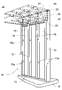
100331 Referring to Figs. 1- 5, a pre-cast concrete wall system incorporating
the
principles of the instant invention can best be seen. The wall panel 10 is pre-
cast in a
form at a manufacturing plant, as is reflected in Figs. 6 and 7 and will be
described in
greater detail below, and then transported when the concrete is cured to the
job site for
installation according to a known process involving the mounting of the walls
10 on a bed
of crushed stone B and fastening the wall panels 10 together in a pre-arranged
manner to
form a basement or foundation wall on which a building will be subsequently
erected.
The wall panel 10 is formed with a generally horizontally oriented footer beam
12, an
upper bond beam 15 oriented generally parallel to the footer beam 12, and a
pre-defined
number of generally vertical concrete studs 13 extending between the footer
beam 12 and
the upper bond beam 15. Between the concrete studs 13, the recessed wall shell
14 is
insulated with a sheet of polystyrene 16 facing the interior side of the wall
10. Preferably,
the concrete studs 13 are formed with access holes or chases 13a passing
generally
horizontally through the concrete studs 13 to allow the passage of wiring or
plumbing
within the confines of the wall panel 10.
100341 In the wall panel 10 depicted in the drawings, a truss ledge 20 is
formed
with the wall shell 14 and upper bond beam 15 to project upwardly above the
upper bond
-7-
CA 02515662 2005-08-11
beam 15 when assembled into a basement foundation. The truss ledge 20 has an
outer
concrete shell 22 that is contiguous with the wall shell 14 and the upper bond
beam 15
and terminates at a top surface 23 elevated above the upper bond beam 15 to
receive a
floor truss system 48 as will be described in greater detail below. The
interior surface of
the truss ledge 20 is faced with an insulation panel 24 in the same manner as
the wall
shell 14 below the upper bond beam 15. The overall thickness of the truss
ledge 20 is less
than that of the upper bond beam 15 thus forming a truss support surface 25 on
top of the
upper bond beam 15.
[0035] Typically, a sill plate 29 is affixed to the truss support surface 25
on top of
the upper bond beam 15 to provide a uniform fastening medium for the floor
trusses 48 to
be mounted to the basement foundation. When the floor trusses 48 are properly
positioned on the truss support surface 25, the top surface 23 of the truss
ledge 20 has a
secondary sill plate 49 for supporting the floor member of the floor trusses
48, whereby
the truss ledge 20 becomes the exterior surface of the flooring system 48 for
the building.
Under this configuration, the top surface of the floor to be above the ground
surface
around the foundation and positioned at the same height as the floor surface
over the
portions of the building that are supported on a traditional concrete slab
adjacent to the
basement portion of the building.
[0036] The formation of the wall panel 10 is best seen in Figs. 6 and 7. A
metal
form 30 defining a support for the pouring of concrete to create the wall
panel 10 is
-8-
CA 02515662 2005-08-11
positioned in a horizontal orientation such that the wall panel 10 is formed
horizontally,
as opposed to the deployment of the wall panels 10 in the assemblage of the
basement
foundation in a vertical orientation. The form 30 is manufactured from steel
to provide
durability and to permit the form to be re-used many times before requiring
replacement.
Galvanized stud facing 32, best seen in detail in Figs. 2, 8 and 9, is
positioned along the
form 30 at the locations for formation of the concrete studs 13. Once formed
into the
wall panel 10, the galvanized stud facing 32 becomes the interior surface of
the concrete
studs 13 to allow the attachment of finishing materials (not shown) to create
a finished
basement structure in the completed building.
[0037] Referring now to Figs. 8 and 9, the galvanized stud facing 32 is
manufactured with fold-up reinforcing bar supports 33. Preferably, the
reinforcing bar
supports 33 are stamped into the surface of the facing 32 by cutting out the
material
around each support 33. The surface of the stud facing 32 is preferably ribbed
with three
longitudinally-extending reinforcing ribs 34. At each fold-up reinforcing bar
support 33,
the central reinforcing rib 34 is formed with a dimple cutout 33a that enables
the
reinforcing bar support 33 to be folded perpendicularly to the orientation of
the facing 32
without forming a dimple at the central reinforcing rib 34. The supports 33
are formed in
a "Y" configuration with pointed tips 36 and a V-notch 37 therebetween. The
steel
reinforcing bar 17 for the concrete stud 13 is laid on top of the folded-up
supports 33
-9-
CA 02515662 2008-04-10
within the V-notch to properly position the reinforcing bar within the
finished concrete
stud 13.
[0038] Before the reinforcing bar 17 is placed on the supports 33, a U-shaped
polystyrene
foam channel 35, best shown in Figs. 5 and 10, is placed over the folded-up
supports 33
with the pointed tips 36 punching through the polystyrene foam material. The
channel 35
defines the outer surface of the concrete stud 13, supported by the galvanized
stud facing
32 placed in the form 30. The top of the legs of the polystyrene foam channel
35 are formed with
support ledges 38 on which the polystyrene insulation sheets 16 are placed for
support
thereof in the final wall assembly. The tops of the legs of the foam channel
35 are formed with rounded interiol
corners 39 to eliminate stresses otherwise encountered with square concrete
corners. The
channels 35 can also be used to mount spreader wires 42 that are positioned
near the
footer beam 12 to maintain the spacing of the upright walls of the channel 35
and to
provide a support for one of the steel reinforcing bars 18 to be placed into
the heel of the
footer beam 12. Another steel reinforcing bar 18 is located at the toe of the
footer beam
12 and is properly positioned by a rebar support wheel 44 supported by the
form 30.
100391 The form 30 is oriented to provide support for the polystyrene
insulation
board 16 on the interior face of the truss ledge 20 above the upper bond beam
15. A steel
reinforcing bar 19 is supported on respective rebar support wheels 44 to
extend from the
concrete portion of the truss ledge 20 through the upper bond beam 15 and into
the
concrete stud, thus structurally tying these concrete portions together. One
skilled in the
-10-
CA 02515662 2005-08-11
art will recognize that openings for windows and doors, which have not been
shown and
described herein, but are within the state of the art of forming pre-cast
concrete wall
systems, may be formed in a conventional manner within the wall panels 10.
Similarly, it
is within the conventional state of the art to form wall panels 10 that are to
be located at
the corners of the completed basement foundation structure with bevel edges at
45 degree
angles to mate into a corner of the foundation.
[0040] The access openings 13a are formed by locating foam inserts 45 between
the upright walls of the polystyrene foam channels 35. By using hollow foam
inserts, the
chases 13a will be insulated between the wiring or plumbing passing through
the opening
13a and the surrounding concrete stud 13. The chase insulation diminishes the
accumulation of condensation in the wall panel 10. Finishing the basement wall
is
accomplished by fastening finishing material, such as drywall or paneling, to
the interior
faces of the concrete studs 13, which are faced with the galvanized stud
facing 32 and the
polystyrene foam channel 35. The galvanized stud facings 32 provide structure
for the
engagement of fasteners connecting the finishing material to the wall panels
10.
[0041] The invention of this application has been described above both
generically
and with regard to specific embodiments. Although the invention has been set
forth in
what is believed to be the preferred embodiments, a wide variety of
alternatives known to
those of skill in the art can be selected within the generic disclosure. The
invention is not
otherwise limited, except for the recitation of the claims set forth below.
-11-