Note : Les descriptions sont présentées dans la langue officielle dans laquelle elles ont été soumises.
CA 02515805 2005-08-11
RETURN MAILER
BACKGROUND OF THE INVENTION
The invention relates generally to return mailers, and more particularly to
return mailers adapted for attaching an enclosed article to an object during
shipment, and returning the article after the obj ect has reached its
destination.
There are many circumstances where it may be desirable to monitor and
record the environmental parameters to which objects are exposed during
transit.
For example, the quality and safety of pharmaceuticals, food products,
chemicals,
and biological products can be adversely affected by improper temperature
control
during processing, distribution, and storage.
Electronic monitoring devices, such as data loggers, can be used to monitor
and record a variety of different environmental parameters during transit.
Data
loggers are small, battery-powered devices that may be equipped with a
microprocessor, instruments, and a memory for storing data. Data loggers may
be
programmed to take specific measurements at desired time intervals. Data
loggers
can also be programmed with unique identification codes that can be used to
identify the environmental conditions to which a specific object has been
exposed.
The information stored on a data logger can be retrieved and analyzed by
connecting the data logger to a computer or reader that can retrieve and
display the
stored readings. Depending upon design, data loggers can be activated
wirelessly
with a reader, or manually by pushing a button or flipping a switch.
Retrieving and storing data may help suppliers and manufacturers improve
quality control and track possible environmental conditions that could
adversely
affect the object being shipped. To accomplish this task, a data logger may be
shipped with an object. Upon reaching its destination, the information stored
in the
data logger can be retrieved for analysis and storage. In some cases, it may
be
-1-
CA 02515805 2005-08-11
desirable to return the data logger to the point of origin or some other
location for
data retrieval and possible reuse. To return the data logger, the individual
returning the data logger would typically need to place it in an envelope to
be
shipped an appropriate destination. Return mailers could also be used to
return the
data logger. The majority of currently available return mailers are designed
to be
sealed for an initial mailing and then are opened, and resealed for the return
mailing.
The above methods typically require the recipient of the object being
monitored to place the data logger in an envelope and deposit it with a mail
delivery service. This could require the sender to handle the data logger,
address a
label, and ensure that the data logger is properly secured in the envelope. In
some
cases, the organization or individual may not be inclined to take the effort
to timely
place the data logger in an envelope or reseal the return mailer. In other
cases, it
may difficult to locate the data logger for return shipment. In still other
cases, the
1 S data logger or multiple data loggers could be misplaced or misidentified.
All of the
above problems may result in efficiencies in using and returning the data
loggers.
Thus, there exists a need for a return mailer that can be used to securely
attach a data logger to an object, and to quickly and efficiently return the
data
logger after it has reached its destination.
BRIEF SUMMARY OF THE INVENTION
The present invention is a return mailer that is adeptly suited for return
shipment of data loggers after they have completed their environmental
monitoring
functions. The return mailer comprises a pouch for receiving a data logger and
a
flap having a sealing agent that is separated into first and second zones by a
line of
weakening. The first zone of sealing agent seals closed the opening of the
pouch,
and the second zone of sealing agent attaches the mailer to an object. Both
zones
of sealing agent are covered with a single release liner. Removing the release
liner
exposes both zones of sealing agent so that the mailer can be quickly sealed
and
attached to an object. After the object has reached its final destination, the
return
mailer portion can be separated from flap by tearing along the line of
weakening.
The previously sealed return mailer can then be deposited with a postal or
parcel
delivery service for return delivery.
-2-
CA 02515805 2005-08-11
The return mailer of the invention provides an apparatus and method for
efficiently and quickly returning a data logger or other device to its source.
The
line of weakening allows the recipient to easily remove the return portion of
the
mailer from the object. The return mailer can also be placed on an outside
surface
of an object so that it may be easily located by the recipient of the object.
Additionally, sealing the opening of the pouch at the point of origin ensures
that
the data logger is secured within the pouch and may help reduce the need to
further
handle the data logger at the destination of the object.
Thus, the invention provides a return mailer that can be used to efficiently
and quickly attach a pouch containing an electronic monitoring device to an
object,
and return the electronic monitoring device to a desired destination after it
has
completed its monitoring functions.
BRIEF DESCRIPTION OF THE SEVERAL VIEWS OF THE DRAW1NG(S)
Having thus described the invention in general terms, reference will now be
made to the accompanying drawings, which are not necessarily drawn to scale,
and
wherein:
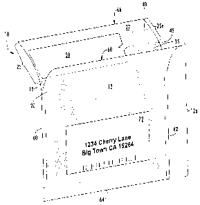
Figure 1 is a graphical illustration of a return mailer that is in accordance
with the invention;
Figure 2 is a side view of the return mailer illustrated in FIG. 1;
Figure 3 is a graphical illustration of an alternate embodiment of a return
mailer having sides edges that are affixed to each other adjacent to the
opening of
the mailer;
Figure 4 is a graphical illustration of a return mailer attached to the side
of
an object; and
Figures SA through SF graphically illustrate the return mailer of the
invention being used in a step-wise manner.
DETAILED DESCRIPTION OF THE INVENTION
The present invention now will be described more fully hereinafter with
reference to the accompanying drawings, in which some, but not all embodiments
of the invention are shown. Indeed, the invention may be embodied in many
different forms and should not be construed as limited to the embodiments set
forth
-3-
CA 02515805 2005-08-11
herein; rather, these embodiments are provided so that this disclosure will
satisfy
applicable legal requirements. Like numbers refer to like elements throughout.
With reference to FIGS. 1 and 2, a return mailer in accordance with the
invention is illustrated and broadly designated as reference number 10. The
return
mailer comprises a pouch 12 and a main flap 25 having a portion comprising a
detachable flap 25a. The pouch 12 comprises a front sheet 15 and a rear sheet
20
that are oriented face-to-face and affixed to each other at side edges 60, 62
and
bottom edge 64. Preferably, each of the side edges and bottom edge are
permanently sealed. In some embodiments the front and rear sheets may comprise
two separate sheets, or alternatively, a single sheet that has been center-
folded at
bottom edge 64. Together the sheets define pouch 12 having an interior space
for
receiving an article and a pouch opening 14 through which an article can be
placed
into the interior of the pouch.
The top edge 66 of main flap 25 extends from the front sheet 15 beyond the
top edge 68 of the rear sheet along the opening 14 of the pouch. The main flap
25
in some embodiments may merely be a continuous extension of front sheet 15.
The main flap 25 has an inner surface 27 facing in the direction of the rear
sheet
20. In some embodiments, the detachable flap ZSa may be connected to the pouch
by a line of weakening 45, for example by providing a score line or plurality
of
perforations in a single sheet to form two portions connected to each other by
the
line of weakening. The term "line of weakening" includes any structure or
configuration adapted to facilitate the selective removal of one portion on
one side
of the line of weakening from another portion on the opposite side of the line
of
weakening. In some embodiments, the line of weakening 45 may extend laterally
across the main flap 25. In other embodiments, the line of weakening may be
disposed within the interior of the pouch 12 and extend laterally across the
front
sheet 15. Typically, the line of weakening 45 may be disposed adjacent and
parallel to the opening 14 of the pouch. The line of weakening defines
detachable
flap 25a and a removable pouch portion 12a. The line of weakening 45 may be
provided by a plurality of openings or perforations that extend across the
surface of
the main flap. The perforations should be spaced sufficiently close to one
another
-4-
CA 02515805 2005-08-11
along the line 45 so that the removable pouch portion can be easily separated
from
the detachable flap.
A sealing agent, such as a pressure sensitive adhesive, is disposed at least
partially on the inner surface 27 of the detachable flap 25a. The sealing
agent
typically comprises first 35 and second 40 sealing agent zones, also referred
to as
adhesive zones, disposed on opposite sides of the line of weakening 45. The
first
adhesive zone 35 is typically disposed between the pouch opening 14 and the
line
of weakening 45. The first adhesive zone 35 is adapted for sealing closed the
opening of the pouch, and the second adhesive zone 40 is adapted for attaching
the
pouch 12 to an object. The adhesive zones may comprise a continuous surface of
adhesive separated by the line of weakening, or alternatively, may comprise
separate and distinct stripes of adhesive that are spaced apart. The sealing
agent
may comprise a variety of materials including, but not limited to, adhesive or
paste, tape, and similar materials that are suitable for sealing the opening
of the
pouch and attaching the flap to the surface of an object.
In some embodiments, the first and second adhesive zones may be
substantially disposed on the main flap 25. In this embodiment, the first
adhesive
zone may cooperate with a closure flap disposed on the rear sheet opposite the
first
sealing agent zone. In this regard, FIG. 2 illustrates a return mailer 10
having a
detachable flap 25a and a closure flap 30. The front and rear sheets 15, 20
are
attached at side edges 60, 62. An upper portion of the rear sheet 20 extends
upwardly above the attached side edges 60, 62 defining closure flap 30. At a
desired time, the first adhesive zone 35 may be brought into face-to-face
sealing
contact with the closure flap 30 to seal closed the opening 14 of the pouch.
Alternatively, the first adhesive zone 35 may be at least partially disposed
on an interior surface of the front sheet. In this embodiment, the first zone
of
adhesive may be disposed in the interior of the pouch adjacent to the opening
14 of
the pouch. In this regard, FIG. 3 illustrates a return mailer 10a having the
first
adhesive zone 35 disposed on the interior surface of the front sheet 15. As
shown
in FIG. 3, the return mailer l0a may have side edges 60, 62 that are attached
to
each other adjacent to top edge 68 of the rear sheet 20.
-5-
CA 02515805 2005-08-11
The return mailer 10, l0a may also comprise a release liner for protecting
the adhesive from premature contact with objects or other portions of the
mailer.
In this regard, FIGS. 1 through 3 illustrate a return mailer having a release
liner 50
covering both adhesive zones 35, 40 simultaneously. The release liner is
releasably adhered to the adhesive zones and protects the adhesive before use.
At a
desired time, the release liner 50 can be removed to expose both adhesive
zones.
The pouch opening 14 can then be sealed closed by pressing the first adhesive
zone
35 into sealing contact with the closure flap 30 or an inner surface of the
rear sheet
20 that is opposite the first adhesive zone. The second adhesive zone 40 can
then
be brought into sealing contact with a surface of an object to which the
return
mailer is to be attached. In this regard, FIG. 4 illustrates an object 100 in
the form
of a package having a return mailer attached to a surface. The use of a single
release liner allows the return mailer in some embodiments to be sealed closed
and
attached to an object substantially simultaneously. As a result, an article
may be
secured within the pouch so that it will not inadvertently fall out or require
further
handling at the point of destination. The return mailer provides an efficient
process for returning an article, such as a data logger, to the point of
origination or
some other desirable location. In some embodiments, the return mailer may also
include a return address indicia 72 that can be preprinted onto the return
portion of
the pouch. In some embodiments, the return address may be printed on a card or
label that has been inserted into the interior of the pouch. The return
address
indicia should make it easier for the recipient to deposit the return pouch
portion of
the mailer with a postal or parcel delivery service. The interior of the pouch
may
also include a cushioning material, such as an air cellular material, for
protecting
the article from damage that could occur during transit.
The material from which the pouch may be formed comprises a wide
variety of materials including, but not limited to, thermoplastic material,
cardboard, paperboard, paper, or the like. The edges 60, 62, 64 of the pouch
can
be attached to each other using a variety of bonding techniques including, for
example, an adhesive. In embodiments where the pouch 12 comprises a
thermoplastic material, the edges 60, 62, 64 of the pouch can be formed by
-6-
CA 02515805 2005-08-11
bonding the front and rear sheet to each other with an adhesive, thermal,
ultrasonic
fusion, or other suitable bonding method.
With reference to FIGS. SA through SF, a data logger is shown being used
with a return mailer that is in accordance with the invention. FIG. SA
illustrates a
S data logger 120 being inserted into the return mailer 10 through pouch
opening 14.
Depending upon the particular design of the data logger being used, the data
logger
can be activated before or after it has been inserted into the pouch. The data
logger
may also be activated after the return mailer has been attached to the object.
As
shown in FIG. SA, the return mailer may also include a return address to help
facilitate the efficient return of the data logger.
FIGS. SB through SD illustrate removing the release liner 50 to expose the
first and second adhesive zones 35, 40, and attaching the mailer to an object.
The
pouch opening 14 may then be sealed closed by pressing the first adhesive zone
35
into sealing contact with the rear sheet 20. At the same time, or in a
subsequent
step, the return mailer may then be attached to object 100 by contacting the
second
adhesive zone 40 to a surface of the object. If desired, the pouch can be
sealed and
attached to the object at substantially the same moment by removing the
release
liner followed by simultaneously pressing the second adhesive zone against the
object while applying pressure against the first adhesive zone 35 so that the
opening of the pouch is sealed closed. After the return mailer has been
attached to
the object and the data logger activated, the object is ready for shipment.
During
transit the data logger will monitor and record the environmental conditions
to
which the object has been exposed.
After the object 100 has reached its desired destination, the return pouch
portion of the mailer can be easily detached from the detachable flap 25a by
tearing along the line of weakening 45. In this regard, Fig. SE illustrates
the return
pouch portion 12a of the mailer being detached from the detachable flap 2Sa.
As
shown in FIG. SE, the return pouch portion 12a can now be deposited with a
postal
or parcel delivery service for shipment to the point of origin. The recipient
does
not have to place the data logger in a return mailer or other envelope. As a
result,
the process for returning a data logger or other article may be simple and
efficient.
CA 02515805 2005-08-11
In some embodiments, the recipient may also be able to retrieve data from
the data logger without having to handle or remove the data logger from the
pouch.
In some embodiments, the data logger may include a radio frequency (RF)
transceiver for wireless communication with a reader. As a result, the
recipient
may also be able to monitor and track environmental conditions before
returning
the data logger. In some embodiments, the return mailer may also be supplied
with
instructions for handling the mailer and retrieving stored data from the
electronic
monitoring device. The instructions in some embodiments may be printed on the
exterior surface of the envelope, typically on the outer surface opposite the
address
indicia. Alternatively, the instructions could be printed on a card that may
be
disposed in the interior of the envelope, and that may be read through the
envelope
by the recipient. Possible instructions can include what to do with the object
or
goods if the retrieved data indicates that a predetermined environmental
threshold,
such as temperature exposure, has been exceeded. For instance, if the object
is
temperature sensitive, the instructions could instruct the recipient, for
example, to
retain, return, discard, or sell the object at a discounted price, or the
like.
Typically, if no predetermined event or environmental threshold has been
exceeded, the object will be retained and handled in a usual or ordinary
manner.
The instructions could also instruct the recipient on how the retrieved data
should
be further handled, such as analyzed, stored, deleted, forwarded to a desired
recipient, or the like. In some cases, it may be desirable to compile a
database for
tracking various conditions and exposure histories that may occur during
transit.
It should be recognized that the return mailer may be used to enclose and
return a variety of different articles. For example, articles such as time-
temperature indicators, shock labels, tracking data, and the like can be used
in the
practice of the invention.
Many modifications and other embodiments of the invention set forth
herein will come to mind to one skilled in the art to which the invention
pertains
having the benefit of the teachings presented in the foregoing descriptions
and the
associated drawings. Therefore, it is to be understood that the invention is
not to
be limited to the specific embodiments disclosed and that modifications and
other
embodiments are intended to be included within the scope of the appended
claims.
_g_
CA 02515805 2005-08-11
Although specific terms are employed herein, they are used in a generic and
descriptive sense only and not for purposes of limitation.
-9-