Sélection de la langue

Search

Sommaire du brevet 2518168 

Énoncé de désistement de responsabilité concernant l'information provenant de tiers

Une partie des informations de ce site Web a été fournie par des sources externes. Le gouvernement du Canada n'assume aucune responsabilité concernant la précision, l'actualité ou la fiabilité des informations fournies par les sources externes. Les utilisateurs qui désirent employer cette information devraient consulter directement la source des informations. Le contenu fourni par les sources externes n'est pas assujetti aux exigences sur les langues officielles, la protection des renseignements personnels et l'accessibilité.

Disponibilité de l'Abrégé et des Revendications

L'apparition de différences dans le texte et l'image des Revendications et de l'Abrégé dépend du moment auquel le document est publié. Les textes des Revendications et de l'Abrégé sont affichés :

  • lorsque la demande peut être examinée par le public;
  • lorsque le brevet est émis (délivrance).
(12) Demande de brevet: (11) CA 2518168
(54) Titre français: FILTRE A MEMBRANE DE ROBINET DE CHASSE
(54) Titre anglais: FLUSH VALVE DIAPHRAGM FILTER
Statut: Réputée abandonnée et au-delà du délai pour le rétablissement - en attente de la réponse à l’avis de communication rejetée
Données bibliographiques
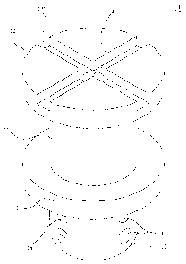
Abrégés

Abrégé anglais


A flush valve diaphragm filter has a filter body forming a recess
section for being assembled to a diaphragm. The filter body defines a main
passageway longitudinally therethrough and a plurality of branch
passageways transverse therethrough. The branch passageways
communicate with the main passageway, and have diameters smaller than
the diameter of the main passageway. The flush valve diaphragm filter
effectively decreases the ratio of fluid passage being fully clogged, and
guides strip-like fibre and lichens to the exterior. Correspondingly, the
water filtering function is enhanced.

Revendications

Note : Les revendications sont présentées dans la langue officielle dans laquelle elles ont été soumises.


Claims:
1. A flush valve diaphragm filter, adapted to be assembled on a diaphragm
bypass of a flush valve, comprising a filter body forming a recess section,
and defining:
a main passageway longitudinally therethrough; and
a plurality of branch passageways transversely therethrough and
communicating with the main passageway;
wherein the branch passageways have diameters smaller than a diameter
of the main passageway.
2. The flush valve diaphragm filter as claimed in claim 1, wherein the
branch passageways are bilaterally symmetrical and are arranged in a
parallel or an unparallel manner.
3. The flush valve diaphragm filter as claimed in claim 1, wherein the
branch passageways are bilaterally unsymmetrical and are arranged in a
parallel or an unparallel manner.
4. The flush valve diaphragm filter as claimed in claim 1, wherein the
recess section is annular, and forms a first flange on the top thereof and a
second flange on the bottom thereof.
5. The flush valve diaphragm filter as claimed in claim 4, wherein the first
flange defines a groove on the top surface thereof.
6. The flush valve diaphragm filter as claimed in claim 5, wherein the
groove is cross-like.
7. The flush valve diaphragm filter as claimed in claim 1, wherein the
diaphragm is a cylinder, and wherein eight branch passageways are
distributed in two layers symmetric to each other, and branch
passageways on each layer are spaced the same distance 90 ° from each
other.
5

Description

Note : Les descriptions sont présentées dans la langue officielle dans laquelle elles ont été soumises.

CA 02518168 2005-09-06
SPECIFICATION
FLUSH VALVE DIAPHRAGM FILTER
BACKGROUND OF THE INVENTION
1. FIELD OF THE INVENTION
[0001 ) The present invention relates to a flush valve diaphragm filter, and
particularly to a flush valve diaphragm filter used in sanitation equipment,
like urinals and water closets, for filtering water thereby preventing
particulates from clogging water passageways.
2. RELATED ART
[0002) Flush valve diaphragms are often mounted on sanitation
equipment like urinals and water closets. As shown in Fig. l, the flush valve
8 has a diaphragm 80 sealing off a central passageway 810 of a barrel
section 81. The barrel section 81 defines a bypass 801 serving as fluid
communication between an inlet 82 and the barrel section 81. Water flows
from the inlet 82 and the bypass 801, into the barrel section 81. Fluid
pressure forces the diaphragm 80 in place to close the central passageway
810. In the closed position, water is stored in the barrel section 81 and is
prohibited to flow out of an outlet 86. When a handle 84 of the flush valve 8
moves to drive a stem 85, a water pressure difference is produced in the
barrel section 81. Water stored in the barrel section 81 flows through the
outlet 86 for flushing.
[0003) Fluid often brings particulates, such as dust, rust, sundries and etc.,
to the barrel section 81, clogging the bypass 801 and therefore affecting the
performance of the diaphragm 80. U.S. Patent Application Serial No.
10/615,614 discloses a bypass orifice filter insert for use in a flush valve
diaphragm. Refernng to Fig. 2, the bypass orifice filter insert 9

CA 02518168 2005-09-06
longitudinally defines a slit 90 therethrough. The slit 90 has a first portion
with a relatively large diameter and extending into a barrel section, and a
second portion with a relatively small diameter. The bypass orifice filter
insert 9 can filter water through the slit 90, solving the problem of clogging
the water passage.
[0004] However, the bypass orifice filter insert 9 in Fig. 2 does not
effectively overcome this defect. Further referring to Figs. 3 and 4, the slit
90 is separate. The first portion 901 and the second portion 902 share a
common center line, and are arranged in the same direction as the water
l0 flows. So dust, rust, grain sundries, fibre and lichens may directly clog
the
second portion 902 with a relatively small diameter, and correspondingly,
water cannot flow into the first portion 901 with a relatively large diameter
and cannot flush a water bowl.
SUMM ARY OF THE INVENTION
[0005] Accordingly, the object of the present invention is to provide a
flush valve diaphragm filter effectively preventing particulates from
clogging the fluid passageway.
[0006] The flush valve diaphragm filter comprises a filter body forming a
recess section. The filter body defines a main passageway longitudinally
therethrough and a plurality of branch passageways transversely
therethrough. The branch passageways communicate with the main
passageway, and have diameters smaller than the diameter of the main
passageway.
BRIEF DESCRIPTION OF THE DRAWINGS
[0007] Fig. I is a partial sectional view of a prior art flush valve with a
conventional diaphragm assembly.
2

CA 02518168 2005-09-06
[0008] Fig. 2 is a plan view of a flush valve diaphragm assembly of U.S.
patent Application Serial No. 10/615,614.
[0009] Figs. 3 and 4 schematically show that water is filtered by
conventional diaphragm assembly in Fig. 2.
[0010] Fig. 5 is a perspective view of a flush valve diaphragm filter in
accordance with the present invention.
[001 I ] Fig. 6 is a partial sectional view of the flush valve diaphragm
filter of Fig. 5.
[0012] Fig. 7 is a sectional view of the flush valve diaphragm filter being
l0 assembled on a bypass of a diaphragm filter.
[0013] Figs. 8 and 9 schematically show water being filtered by the flush
valve diaphragm filter of Fig. 7.
DESCRIPTION OF THE PREFERRED EMBODIMENTS
[0014] With reference to Figs. 5 and 6, a flush valve diaphragm f lter 1 in
accordance with the present invention comprises a filter body 10 defining an
annular recess section 11 for corresponding to a bypass 20 of a diaphragm 2
(shown in Fig. 7). In one embodiment, the diaphragm 2 is a cylinder. The
recess section I 1 forms a first flange 12 on a top thereof and a second
flange
13 on a bottom thereof. T'he first flange 12 defines a cross-like groove 121
on a top surface thereof for guiding fluid. The filter body 10 defines a main
passageway 14 longitudinally therethrough and generally in the center
thereof. Eight branch passageways 15 are transversely formed below the
second flange 13 and have smaller diameters compared to the main
passageway 14. The branch passageways 15 respectively communicate with
the main passageway 14 and are arranged in two layers symmetrical to each
3

CA 02518168 2005-09-06
other. The branch passageways 15 on each layer are spaced the same
distance 90° from each other. In one embodiment, the branch passageways
15 are bilaterally symmetrical and are arranged in a parallel or an unparallel
manner. In another embodiment, the branch passageways 15 are bilaterally
unsymmetrical and are arranged in a parallel or an unparallel manner. With
continued reference to Fig. 7, when the flush valve diaphragm filter 1 is
assembled on the bypass 20 of the diaphragm 2, the bypass 20 is tilted and
slightly expands to enclose the recess section 11 due to the flexibility of
the
diaphragm 2.
l0 [0015] With reference to Figs. 8 and 9, each branch passageway 15 has a
filtering function. Water flows through and is filtered by multiple branch
passageways 15. Sundries in water have to block all the branch passageways
to block water entirely; otherwise unclogged branch passageways 15 may
allow water to flow therethrough and into the main passageway 14. For
15 example, even if particulates 60 in water block two branch passageways 15,
other branch passageways 15 can provide fluid passage communicating to
the main passageway 14 (shown in Fig. 8). Similarly, the branch
passageways 15 may guide small strip-like fibre and lichens to exterior
owing to the transverse arrangement thereof, thereby avoiding the main
passageway 14 stuffing. Even if large strip-like fibre and lichens block two
branch passageways 15, other branch passageways 15 may still Iead the
fluid to the main passageway 14. The branch passageways 15 effectively
decrease the ratio of fluid passages being fully clogged, and therefore
enhance the water filtering capability.
[0016] It is understood that the invention may be embodied in other
forms without departing from the spirit thereof. Thus, the present examples
and embodiments are to be considered in all respects as illustrative and not
restrictive, and the invention is not to be limited to the details given
herein.
4

Dessin représentatif
Une figure unique qui représente un dessin illustrant l'invention.
États administratifs

2024-08-01 : Dans le cadre de la transition vers les Brevets de nouvelle génération (BNG), la base de données sur les brevets canadiens (BDBC) contient désormais un Historique d'événement plus détaillé, qui reproduit le Journal des événements de notre nouvelle solution interne.

Veuillez noter que les événements débutant par « Inactive : » se réfèrent à des événements qui ne sont plus utilisés dans notre nouvelle solution interne.

Pour une meilleure compréhension de l'état de la demande ou brevet qui figure sur cette page, la rubrique Mise en garde , et les descriptions de Brevet , Historique d'événement , Taxes périodiques et Historique des paiements devraient être consultées.

Historique d'événement

Description Date
Demande non rétablie avant l'échéance 2009-09-08
Le délai pour l'annulation est expiré 2009-09-08
Réputée abandonnée - omission de répondre à un avis sur les taxes pour le maintien en état 2008-09-08
Inactive : Abandon. - Aucune rép dem par.30(2) Règles 2008-08-28
Inactive : Dem. de l'examinateur par.30(2) Règles 2008-02-28
Modification reçue - modification volontaire 2007-12-07
Inactive : Dem. de l'examinateur art.29 Règles 2007-08-20
Inactive : Dem. de l'examinateur par.30(2) Règles 2007-08-20
Demande publiée (accessible au public) 2007-03-06
Inactive : Page couverture publiée 2007-03-05
Inactive : CIB attribuée 2006-07-06
Inactive : CIB en 1re position 2006-07-06
Inactive : CIB attribuée 2006-03-19
Demande reçue - nationale ordinaire 2005-10-17
Lettre envoyée 2005-10-17
Inactive : Certificat de dépôt - RE (Anglais) 2005-10-17
Exigences pour une requête d'examen - jugée conforme 2005-09-06
Toutes les exigences pour l'examen - jugée conforme 2005-09-06

Historique d'abandonnement

Date d'abandonnement Raison Date de rétablissement
2008-09-08

Taxes périodiques

Le dernier paiement a été reçu le 2007-09-05

Avis : Si le paiement en totalité n'a pas été reçu au plus tard à la date indiquée, une taxe supplémentaire peut être imposée, soit une des taxes suivantes :

  • taxe de rétablissement ;
  • taxe pour paiement en souffrance ; ou
  • taxe additionnelle pour le renversement d'une péremption réputée.

Les taxes sur les brevets sont ajustées au 1er janvier de chaque année. Les montants ci-dessus sont les montants actuels s'ils sont reçus au plus tard le 31 décembre de l'année en cours.
Veuillez vous référer à la page web des taxes sur les brevets de l'OPIC pour voir tous les montants actuels des taxes.

Historique des taxes

Type de taxes Anniversaire Échéance Date payée
Requête d'examen - générale 2005-09-06
Enregistrement d'un document 2005-09-06
Taxe pour le dépôt - générale 2005-09-06
TM (demande, 2e anniv.) - générale 02 2007-09-06 2007-09-05
Titulaires au dossier

Les titulaires actuels et antérieures au dossier sont affichés en ordre alphabétique.

Titulaires actuels au dossier
GLOBE UNION INDUSTRIAL CORP.
Titulaires antérieures au dossier
HAO-YAO HSIAO
Les propriétaires antérieurs qui ne figurent pas dans la liste des « Propriétaires au dossier » apparaîtront dans d'autres documents au dossier.
Documents

Pour visionner les fichiers sélectionnés, entrer le code reCAPTCHA :


Pour visualiser une image, cliquer sur un lien dans la colonne description du document. Pour télécharger l'image (les images), cliquer l'une ou plusieurs cases à cocher dans la première colonne et ensuite cliquer sur le bouton "Télécharger sélection en format PDF (archive Zip)" ou le bouton "Télécharger sélection (en un fichier PDF fusionné)".

Liste des documents de brevet publiés et non publiés sur la BDBC .

Si vous avez des difficultés à accéder au contenu, veuillez communiquer avec le Centre de services à la clientèle au 1-866-997-1936, ou envoyer un courriel au Centre de service à la clientèle de l'OPIC.


Description du
Document 
Date
(aaaa-mm-jj) 
Nombre de pages   Taille de l'image (Ko) 
Description 2005-09-05 4 177
Abrégé 2005-09-05 1 17
Revendications 2005-09-05 1 39
Dessins 2005-09-05 9 120
Dessin représentatif 2007-02-13 1 7
Description 2007-12-06 4 178
Revendications 2007-12-06 1 38
Accusé de réception de la requête d'examen 2005-10-16 1 176
Courtoisie - Certificat d'enregistrement (document(s) connexe(s)) 2005-10-16 1 106
Certificat de dépôt (anglais) 2005-10-16 1 158
Rappel de taxe de maintien due 2007-05-07 1 109
Courtoisie - Lettre d'abandon (taxe de maintien en état) 2008-11-02 1 175
Courtoisie - Lettre d'abandon (R30(2)) 2008-12-03 1 166
Taxes 2007-09-04 1 34