Note : Les descriptions sont présentées dans la langue officielle dans laquelle elles ont été soumises.
CA 02524075 2005-10-28
WO 2004/099566 PCT/US2004/013165
A Method and Apparatus for
an Advanced Optical Analyzer
s
Background of the Invention
Field of the Invention
[0001] The present invention relates generally to the field of downhole
sampling
analysis and in particular to a sample tank having a window or an internal
light source
to for introduction of electromagnetic energy into a confined fluid sample.
There
response to the introduction of electromagnetic energy into the tank is used
to perform
non-invasive analysis of a sample in the tank without opening the tank or
otherwise
disturbing the sample.
Summary of the Related Art
15 [0002] Earth formation fluids in a hydrocarbon producing well typically
comprise a
mixture of oil, gas, and water. The pressure, temperature and volume of
formation
fluids control the phase relation of these constituents. In a subsurface
formation, high
well fluid pressures often entrain gas within the oil above the bubble point
pressure.
When the pressure is reduced, the entrained or dissolved gaseous compounds
separate
20 from the liquid phase sample. The accurate measurement of pressure,
temperature,
and formation fluid composition from a particular well affects the commercial
viability for producing fluids available from the well. The data also provides
information regarding procedures for maximizing the completion and production
of
the respective hydrocarbon reservoir.
25 [0003] Certain techniques analyze the well fluids downhole in the well
bore. United
States Patent No. 6,467,544 to Brown, et al. describes a sample chamber having
a
slidably disposed piston to define a sample cavity on one side of the piston
and a
CA 02524075 2005-10-28
WO 2004/099566 PCT/US2004/013165
2
buffer cavity on the other side of the piston. United States Patent No.
5,361,839 to
Griffith et al. (1993) disclosed a transducer for generating an output
representative of
fluid sample characteristics downhole in a wellbore. United States Patent No.
5,329,811 to Schultz et al. (I 994) disclosed an apparatus and method for
assessing
pressure and volume data for a downhole well fluid sample.
[0004] Other techniques capture a well fluid sample for retrieval to the
surface.
United States Patent No. 4,583,595 to Czenichow et al. (1986) disclosed a
piston
actuated mechanism for capturing a well fluid sample. United States Patent No.
4,721,157 to Berzin (1988) disclosed a shifting valve sleeve for capturing a
well fluid
to sample in a chamber. United States Patent No. 4,766,955 to Petermann (1988)
disclosed a piston engaged with a control valve for capturing a well fluid
sample, and
United States Patent No. 4,903,765 to Zunkel (1990) disclosed a time-delayed
well
fluid sampler. United States Patent No. 5,009,100 to Gruber et al. (1991)
disclosed a
wireline sampler for collecting a well fluid sample from a selected wellbore
depth.
United States Patent No. 5,240,072 to Schultz et al. (1993) disclosed a
multiple
sample annulus pressure responsive sampler for permitting well fluid sample
collection at different time and depth intervals, and United States Patent No.
5,322,120 to Be et al. (1994) disclosed an electrically actuated hydraulic
system for
collecting well fluid samples deep in a wellbore.
[0005] Temperatures downhole in a deep wellbore often exceed 300 degrees F.
When
a hot formation fluid sample is retrieved to the surface at 70 degrees F, the
resulting
drop in temperature causes the formation fluid sample to contract. If the
volume of the
sample is unchanged, such contraction substantially reduces the sample
pressure. A
pressure drop causes changes in the situ formation fluid parameters, and can
permit
phase separation between liquids and gases entrained within the formation
fluid
CA 02524075 2005-10-28
WO 2004/099566 PCT/US2004/013165
3
sample. Phase separation significantly changes the formation fluid
characteristics, and
reduces the ability to evaluate the actual properties of the formation fluid.
[0006] To overcome this limitation, various techniques have been developed to
maintain pressure of the formation fluid sample. United States Patent No.
5,337,822
to Massie et al. (1994) pressurized a formation fluid sample with a
hydraulically
driven piston powered by a high-pressure gas. Similarly, United States Patent
No.
5,662,166 to Shammai (1997) used a pressurized gas to charge the formation
fluid
sample. United States Patent Nos. 5,303,775 (1994) and 5,377,755 (1995) to
Michaels
et al. disclosed a bi-directional, positive displacement pump for increasing
the
1o formation fluid sample pressure above the bubble point so that subsequent
cooling did
not reduce the fluid pressure below the bubble point.
[0007] Typically, sample tanks are transported to laboratories for analysis
for
determination of formation fluid properties based on the sample. The samples
typically have to be transferred to a transportation tank, thus risking sample
damage
and spoilage due to pressure loss and formation of bubbles or asphaltene
precipitation
within the sample. Moreover, even if the sample is transferred successfully to
the
laboratory, it typically takes weeks or months to receive a full laboratory
analysis of
the sample. Thus there is a need for a rapid sample analysis system that
provides
accurate results and eliminates the risk of sample spoilage.
Summary of the Invention
[0008] The present invention addresses the shortcomings of the related art
described
above. The present invention provides a downhole sample tank having at least
one
window for introduction of visible, near-infrared (Nn2), mid-infrared (MIR)
and other
electromagnetic energy into the tank for samples collected in the sample tank
CA 02524075 2005-10-28
WO 2004/099566 PCT/US2004/013165
4
downhole from an earth boring or well bore. The window is made of sapphire or
another material capable of allowing electromagnetic energy to pass through
the
window. The entire sample tank can be made of sapphire or another material
capable
of allowing electromagnetic energy to pass another material enabling visual
inspection or analysis of the sample inside the sample chamber. The present
invention also provides interior NIR/MIR light sources and sensors that
communicate
from inside of the sample tank via electronic data signals. NIR, MIR and
visible light
analysis (transmittance, reflectance, and absorption) is performed on the
sample via
the window to provide a non-invasive analysis of sample properties and
l0 contamination level. A single window transmits light reflected off a
reflective surface
inside of the sample tank to obtain transmittance data through a single
window.
[0009] The surface and down hole analysis comprises determination of gas oil
ratio,
API gravity and various other physical parameters associated with the sample
which
can be calculated or estimated by a trained neural network or chemometric
equation.
A flexural mechanical or piezoelectric resonator is also provided to estimate
fluid
density and viscosity from which additional parameters can be estimated by a
trained
neural network, non linear least squares fit, chemometric equation or other
soft
modeling techniques well appreciated in the art. The sample tank is over
pressurized
above the bubble point for the sample to prevent adverse pressure drop. When
very
high pressures are desired the sample is supercharged with a pressurization
gas
charge. The down hole sample tank comprises a housing having a hollow interior
and
at least one window, a fiber optics lead, optical conduit or internal light
source or
sensor for introduction and detection of electromagnetic energy into the
sample tank.
Brief Description of the Figures
CA 02524075 2005-10-28
WO 2004/099566 PCT/US2004/013165
[0010] For detailed understanding of the present invention, references should
be made
to the following detailed description of the preferred embodiment, taken in
conjunction with the accompanying drawings, in which like elements have been
given
like numerals, wherein:
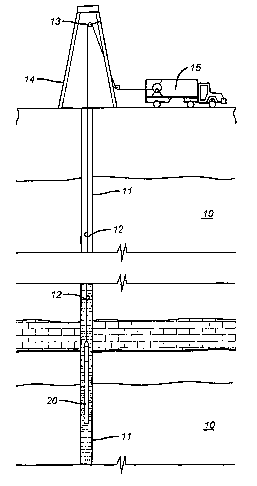
5 FIG. 1 is a schematic earth section illustrating the invention operating
environment;
FIG. 2 is a schematic of the invention in operative assembly with
cooperatively supporting tools;
FIG. 3 is a schematic of a representative formation fluid extraction and
to delivery system;
FIG. 4 is an illustration of a preferred sample chamber and analysis top sub;
FIG. 5 is an illustration of an alternative embodiment having a water pump to
pressurize a sample for analysis by an external unit;
FIG. 6 is an illustration of a common current analysis procedure;
FIG. 7 is an illustration of the new improved procedure provided by the
present invention;
FIG. 8 is an illustration of an alternative embodiment;
FIG. 9 is an illustration of an alternative embodiment having an internal
light
source and sensor;
2o FIG. 10 is an illustration of an alternative embodiment having a single
window and a reflective surface for return of electromagnetic radiation;
FIG. 11 is an illustration of another alternative embodiment using a Raman
spectrometer; and
FIG. 12 is an illustration of another alternative embodiment using an external
analysis equipment and at least one optical window.
CA 02524075 2005-10-28
WO 2004/099566 PCT/US2004/013165
6
Detailed Description of an Exemplary Embodiment
[0011] FIG. 1 schematically represents a cross-section of earth 10 along the
length of
a wellbore penetration 11. Usually, the wellbore will be at least partially
filled with a
mixture of liquids including water, drilling fluid, and formation fluids that
are
indigenous to the earthiformations penetrated by the wellbore. Hereinafter,
such fluid
mixtures are referred to as "wellbore fluids". The term "formation fluid"
hereinafter
refers to a specific formation fluid exclusive of any substantial mixture or
contamination by fluids not naturally present in the specific formation.
to [0012] Suspended within the wellbore 11 at the bottom end of a wireline 12
is a
formation fluid sampling tool 20. The wireline 12 is often carried over a
pulley 13
supported by a derrick 14. Wireline deployment and retrieval is performed by a
powered winch carried by a service truck 15, for example.
[0013] Pursuant to the present invention, an exemplary embodiment of a
sampling
tool 20 is schematically illustrated by FIG. 2. In the present example, the
sampling
tools comprise a serial assembly of several tool segments that are joined end-
to-end
by the threaded sleeves of mutual compression unions 23. An assembly of tool
segments appropriate for the present invention may include a hydraulic power
unit 21
and a formation fluid extractor 23. Below the extractor 23, a large
displacement
2o volume motorlpump unit 24 is provided for line purging. Below the large
volume
pump is a similar motor/pump unit 25 having a smaller displacement volume that
is
quantitatively monitored as described more expansively with respect to FIG. 3.
Ordinarily, one or more sample tank magazine sections 26 are assembled below
the
small volume pump. Each magazine section 26 may have three or more fluid
sample
tanks 30.
CA 02524075 2005-10-28
WO 2004/099566 PCT/US2004/013165
7
[0014] The formation fluid extractor 22 comprises an extensible suction probe
27 that
is opposed by bore wall feet 28. Both, the suction probe 27 and the opposing
feet 28
are hydraulically extensible to firmly engage the wellbore walls. Construction
and
operational details of the fluid extraction tool 22 are more expansively
described by
U.S. Patent No. 5,303,775, the specification of which is incorporated
herewith.
[0015] Turning now to FIG. 4, in an exemplary embodiment of the present
invention,
an advanced optical analyzer (AOA) 800 is provided which comprises a sample
tank
816 having an integral analytical top sub 818. The sample 821 in the sample
tank can
be pressurized by the pressurized compensation system which comprises a
pressure
to compensation system 810, having a nitrogen pressure chamber 812. The
nitrogen
pressure is available when very high pressure is desired. Pressure is applied
sufficient
to keep a down hole fluid sample 821 in chamber 816 above the bubble point
pressure
and above the pressure at which asphaltenes precipitate out of the sample. The
AOA
is also suitable for downhole capture, pressurization and analysis of gas
captured in a
sample 821 confined in chamber 816.
[0016] The present example of the AOA top sub 818 provides one or more optical
conduits, which in this example are high-pressure sapphire windows 814 for
ingress
and egress of electromagnetic energy into the analysis chamber 800 optical
analysis of
parameters of interest for formation fluid sample 821. The entire AOA
including the
analysis chamber can be made of sapphire or another material which enables
electromagnetic energy to pass through the material, thereby enabling visual
inspection and noninvasive spectral and other analysis of the contents of the
AOA,
including the sample chamber. Optical conduits other than a sapphire window
are
acceptable. An analysis module 738 comprising a light source, light sensor and
processor is provided which can be used for analysis of the sample 821 down
hole or
CA 02524075 2005-10-28
WO 2004/099566 PCT/US2004/013165
8
at the surface. Analysis module 738 is in contact with the sample 821 in
sample
region 823 for transmission and reception of NIR/MIR light into and through
the
sample in region 823. The light reflected, fluoresced and transmitted NIR/MIR
light
is analyzed for transmittance, reflectance and luminance by the processor in
analysis
module 738. A flexural mechanical resonator 840 connected to analysis module
738
by communication line 741 is also provided to determine fluid viscosity,
density and
other parameters of interest for the fluid sample using soft modeling
techniques. .
[0017] In surface operations, as shown in FIG. 5, the AOA 800 is removed from
a
sample tank carrier and the sample 821 pressure is stabilized by pumping
pressurized
l0 water 920 behind the piston 921 using pump 910. At this time the nitrogen
can be
released and the nitrogen chamber can be detached from the sample chamber. An
external optical analyzer 930 or analysis module 738 comprising an NIRIMIR
ultraviolet or visible light source and spectrometers provided for surfaces or
down
hole non-invasive analysis. The optical analyzer 930 is connected to a NIR/MIR
light
source 832 and a NIR/MIR light sensor 833 for analysis of light transmittance,
fluorescence and total attenuated reflectance. That is, without disturbing the
fluid
sample or requiring transferring the sample to another Department of
Transportation
(DOT) approved chamber for transport to an off site laboratory for analysis.
[0018] The external optical analyzer 930 or internal analyzer 738 in the
current
2o example uses wavelength ranges from 1500 nm to 2000 nm to scan the fluid
sample
to determine or estimate through soft modeling techniques, parameters of
interest,
such as sample contamination percentage, gas oil ratio (GOR), density and
asphaltene
deposition pressure. A tunable diode laser and a Raman spectrometer are also
provided in analysis module 738 for spectral analysis of the fluid sample.
Each of the
light sources and sensors are located inside of the sample tank 816 or
communicate
CA 02524075 2005-10-28
WO 2004/099566 PCT/US2004/013165
9
with the interior of the sample tank via the optical window 814 or an
equivalent
optical conduit providing data or electromagnetic energy ingress and egress to
the
interior of the sample tank and the sample retained therein.
[0019] The analysis module 738 is attached as an integral part of the sample
tank in
the AOA prior to going down hole. The analysis module is used to perform
NIR/MIR
and other analysis described herein downhole during a run or at the surface
upon
completion of a sampling run downhole. Some of the numerous advantages of the
AOA of the present invention are shown by comparison to FIG. 6, a prior art
system
and FIG. 7, the new method and apparatus design provided by the AOA of the
1o present invention. Note that in FIG. 7 that a primary parameter calculation
by optical
techniques 1114 is available immediately or in less than six hours and a final
PVT
report 1132 in less than a week or less rather than six to eight weeks as
shown in FIG.
6 for the prior art system. An advantage for the disclosed method and
apparatus is
that no sample transfer is required, as non-invasive surface or down hole
equipment in
both the analysis module 738 and external equipment 830 perform PVT and
spectral
analysis to determine asphaltene deposition, bubble point, formation volume
factor,
compositional analysis and additional analysis described herein.
[0020] Turning now to FIG. 8 an alternative embodiment of the present
invention is
presented showing top sub 818 containing analysis module 738 attached to
sample
2o chamber 1210 pressurized by nitrogen (N2) 1212 and hydrostatic pressure
1214 while
down hole. Thus, the present invention can perform sampling and sample
analysis
while down hole or at the surface as shown in FIG. 4, 5 and 8.
[0021] Turning now to FIG. 9, an alternative embodiment is shown wherein an
internal light source 830 and an internal sensor 833 are provided for
noninvasive
optical analysis of the sample 821. The internal processor embedded in
analysis
CA 02524075 2005-10-28
WO 2004/099566 PCT/US2004/013165
module 738, an external analyzer 930 or a surface analyzer in surface truck 15
process
the optical data to determine a parameter of interest for the fluid sample
821. As
shown in FIG 9, to determine viscosity a ball 1301 is held in place by magnet
1317
and released in fluid sample contained in fluid sample chamber 1210. The ball
is
5 sensed by magnetic sensor 1319 upon arrival at point 1319. The processor
determines
the amount of time it takes for ball 1301 to travel between point 1317 and
point 1319
and determines the fluid viscosity therefrom.
[0022] As shown in FIG. 10, analysis window unit comprises analysis module
738,
tunable diode laser spectrometer 1415 or other optical spectrometer and
sorption
10 cooling unit 1416. Sorption cooling unit 1416 is described in co-owned
patent
application serial number 09/756,764 filed on January 8, 2001 entitled
Downhole
Sorption Cooling in Wireline Logging and Monitoring While Drilling" by Rocco
DiFoggio, incorporated herein by reference in its entirety.
[0023] The tunable diode laser 1415 spectrometer enable the ultra high
resolution
spectroscopy downhole or at the surface. Sorption cooling unit 1416 cools the
tunable
diode laser as necessary to obviate the adverse affects of downhole
temperatures.
[0024] Turning now the FIG. 11, an alternative embodiment of the present
invention
is shown providing an external window unit 1510 for surface or downhole
attachment
of analysis equipment such as gas chromatographs or other analysis equipment.
[0025] FIG. 12 is an illustration of an alternative embodiment having a single
optical
conduit 814, in this example a sapphire window 814 for ingress and egress of
electromagnetic energy into and out of the sample chamber 816. Light from
light
source/sensor 832 enter the sample chamber 816 through single optical window
814.
The light travels through the sample and bounces off of reflective surface
815. Thus,
the round trip transmittance can determined from reflection and return of
CA 02524075 2005-10-28
WO 2004/099566 PCT/US2004/013165
11
electromagnetic energy. Transmittance is determined for round trip travel of
the light
through the optical conduit, through the sample, reflected off of the
reflective surface,
returned through the sample and back through the optical conduit for
measurement.
Attenuated total reflectance and fluorescence response data are also sensed
but do not
use the reflective surface 815. The data is processed by processor in analysis
module
738, internal analyzer/processor 930 or surface truck/controller/processor 15.
[0026] In another embodiment, the method and apparatus of the present
invention is
implemented as a set computer executable of instructions on a computer
readable
medium, comprising ROM, RAM, CD-ROM, Flash RAM or any other computer
1o readable medium, now known or unknown that when executed cause a computer
to
implement the functions of the present invention.
[0027] While the foregoing disclosure is directed to the preferred embodiments
of the
invention various modifications will be apparent to those skilled in the art.
It is
intended that all variations within the scope of the appended claims be
embraced by
the foregoing disclosure. Examples of the more important features of the
invention
have been summarized rather broadly in order that the detailed description
thereof that
follows may be better understood, and in order that the contributions to the
art may be
appreciated. There are, of course, additional features of the invention that
will be
described hereinafter and which will form the subject of the claims appended
hereto.