Sélection de la langue

Search

Sommaire du brevet 2524182 

Énoncé de désistement de responsabilité concernant l'information provenant de tiers

Une partie des informations de ce site Web a été fournie par des sources externes. Le gouvernement du Canada n'assume aucune responsabilité concernant la précision, l'actualité ou la fiabilité des informations fournies par les sources externes. Les utilisateurs qui désirent employer cette information devraient consulter directement la source des informations. Le contenu fourni par les sources externes n'est pas assujetti aux exigences sur les langues officielles, la protection des renseignements personnels et l'accessibilité.

Disponibilité de l'Abrégé et des Revendications

L'apparition de différences dans le texte et l'image des Revendications et de l'Abrégé dépend du moment auquel le document est publié. Les textes des Revendications et de l'Abrégé sont affichés :

  • lorsque la demande peut être examinée par le public;
  • lorsque le brevet est émis (délivrance).
(12) Brevet: (11) CA 2524182
(54) Titre français: DISPOSITIF DE FIXATION POUR LE COUPLAGE D'UN DISPOSITIF DE TRANSPORT
(54) Titre anglais: A CLAMPING DEVICE FOR COUPLING A MEANS OF TRANSPORT
Statut: Périmé et au-delà du délai pour l’annulation
Données bibliographiques
(51) Classification internationale des brevets (CIB):
  • B61B 12/12 (2006.01)
(72) Inventeurs :
  • LUGER, PETER (Autriche)
  • MEINDL, BERND (Autriche)
(73) Titulaires :
  • INNOVA PATENT GMBH
(71) Demandeurs :
  • INNOVA PATENT GMBH (Autriche)
(74) Agent: BORDEN LADNER GERVAIS LLP
(74) Co-agent:
(45) Délivré: 2010-04-27
(22) Date de dépôt: 2005-10-24
(41) Mise à la disponibilité du public: 2006-05-04
Requête d'examen: 2007-06-06
Licence disponible: S.O.
Cédé au domaine public: S.O.
(25) Langue des documents déposés: Anglais

Traité de coopération en matière de brevets (PCT): Non

(30) Données de priorité de la demande:
Numéro de la demande Pays / territoire Date
1842/2004 (Autriche) 2004-11-04

Abrégés

Abrégé français

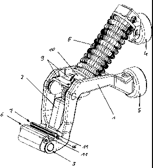
La présente concerne un dispositif de serrage pour réunir un moyen de transport, par exemple un habitacle ou une chaise, à un câble de traction ou un système de câblage. Le dispositif comprend deux mâchoires de serrage (6, 7) qui peuvent être déplacées l'une vers l'autre ou éloignées l'une de l'autre, aux fins du raccordement du dispositif de serrage ou du détachement au câble de traction. Des mâchoires interchangeables (11), par lesquelles les mâchoires de serrage (6, 7) agissent sur le câble de traction, sont fixées aux mâchoires de serrage (6, 7). Les mâchoires de serrage (6,7) comportent une surface porteuse (14) sur laquelle viennent s'appuyer les mâchoires interchangeables et cette surface présente une courbe concave, tandis que les mâchoires interchangeables (11) sont pourvues d'une contre-surface (13) convexe correspondante.


Abrégé anglais

A clamping device for coupling a means of transport, for example a cabin or a chair, to the hauling or traction cable of a cableway system, comprises two clamping jaws (6, 7) which can be moved toward one another or apart for coupling the clamping device to and uncoupling it from the hauling or traction cable. Exchangeable jaws (11), via which the clamping jaws (6, 7) act on the hauling or traction cable, are fastened to the clamping jaws (6, 7). A bearing surface (14) on the clamping jaws (6, 7) for the exchangeable jaws (11) is curved concavely, and a countersurface (13) on the exchangeable jaws (11) has a corresponding curvature.

Revendications

Note : Les revendications sont présentées dans la langue officielle dans laquelle elles ont été soumises.


-9-
CLAIMS:
1. A clamping device for coupling a transport device to a
hauling or traction cable of a cableway system, the clamping
device comprising:
two clamping jaws moveable toward one another or apart
for coupling the clamping device to and uncoupling the
clamping device from the hauling or traction cable;
exchangeable jaws, through which said clamping jaws act
on the hauling or traction cable, being fastened to said
clamping jaws;
said clamping jaws having a bearing surface for
receiving said exchangeable jaws, said bearing surface being
curved concavely;
said exchangeable jaws having a counter surface with a
curvature corresponding to said bearing surface and said
counter surface resting on said bearing surface; and
said exchangeable jaws each containing two cheeks
extending laterally next to a respective one of said
clamping jaws.
2. The clamping device according to claim 1, wherein said
bearing surface and said counter surface are curved with a
circular cylindrical shape.
3. The clamping device according to claim 1 or 2, wherein
said exchangeable jaws have a contact surface with which
said exchangeable jaws act on the hauling or traction cable
and said contact surface has a shape substantially parallel
to said counter surface.
4. The clamping device according to claim 3, wherein said
contact surface has a discontinuous curvature profile with a
radius of curvature in a central curvature region being
smaller than a radius of curvature of the cable.

-10-
5. The clamping device according to claim 4, wherein said
radius of curvature of said contact surface increases
outward from said central curvature region and merges with a
substantially plane region.
6. The clamping device according to claim 3, 4, or 5,
wherein said contact surface has a central region with
groove-shaped depressions formed therein.
7. The clamping device according to claim 3, 4, or 5,
wherein said contact surface has a central region with a
slot-shaped depression formed therein.
8. The clamping device according to any one of claims 1 to
7, wherein said cheeks contain shoulders on sides facing one
another, said cheeks having projections and returns on said
shoulders, a distance between said projections of said
shoulders of said two cheeks being smaller than a distance
between said returns on said cheeks.
9. The clamping device according to claim 8, wherein said
projections are disposed in a region next to said counter
surface of said exchangeable jaws.
10. The clamping device according to claim 8 or 9, wherein
said projections have a width being approximately 15-50% of
a width of said cheeks.
11. The clamping device according to claim 9 or 10,
wherein:
said cheeks each have a mounting bore formed therein;
and
said projections extend as far as approximately into a
region of said mounting bore or slightly into said region of
said mounting bore.

-11-
12. The clamping device according to claim 8 or 9, wherein
said projections have a width being approximately 20-30% of
a width of said cheeks.
13. The clamping device according to any one of claims 1 to
12, wherein the transport device is a cabin, a gondola, or a
chair.
14. A clamping device for coupling a transport device to a
hauling or traction cable of a cableway system, the clamping
device comprising:
two clamping jaws moveable toward one another or apart
for coupling the clamping device to and uncoupling the
clamping device from the hauling or traction cable;
exchangeable jaws, through which said clamping jaws act
on the hauling or traction cable, being fastened to said
clamping jaws;
said clamping jaws having a concavely curved bearing
surface for receiving said exchangeable jaws;
said exchangeable jaws having a counter surface with a
curvature corresponding to said bearing surface and a
contact surface with which said exchangeable jaws act on the
hauling or traction cable, said contact surface having a
shape substantially parallel to said counter surface and
having a central region with a slot-shaped depression or
groove-shaped depressions formed and therein; and
said exchangeable jaws each containing two cheeks
extending laterally next to a respective one of said
clamping jaws.
15. A clamping device for coupling a transport device to a
hauling or traction cable of a cableway system, the clamping
device comprising:
two clamping jaws moveable toward one another or apart
for coupling the clamping device to and uncoupling the
clamping device from the hauling or traction cable;

-12-
exchangeable jaws, through which said clamping jaws act
on the hauling or traction cable, being fastened to said
clamping jaws, said exchangeable jaws each containing two
cheeks extending laterally next to a respective one of said
clamping jaws; and
said clamping jaws having a bearing surface for
receiving said exchangeable jaws, said bearing surface being
curved concavely; and
said exchangeable jaws having a counter surface with a
curvature corresponding to said bearing surface.
16. The clamping device according to claim 15, wherein said
cheeks contain shoulders on sides facing one another, said
cheeks having projections and returns on said shoulders, a
distance between said projections of said shoulders of said
two cheeks being smaller than a distance between said
returns on said cheeks.
17. The clamping device according to claim 16, wherein said
projections are disposed in a region next to said counter
surface of said exchangeable jaws.
18. The clamping device according to claim 16 or 17,
wherein said projections have a width being approximately
15-50% of a width of said cheeks.
19. The clamping device according to claim 16, 17, or 18,
wherein:
said cheeks each have a mounting bore formed therein;
and
said projections extend as far as approximately into a
region of said mounting bore or slightly into said region of
said mounting bore.

Description

Note : Les descriptions sont présentées dans la langue officielle dans laquelle elles ont été soumises.


CA 02524182 2005-10-24
A clamping device for coupling a means of transport
The invention relates to a clamping device for coupling
a means of transport, for example a cabin or a chair,
to the hauling or traction cable of a cableway system,
with two clamping jaws which can be moved toward one
another or apart for coupling the clamping device to
and uncoupling it from the hauling or traction cable,
exchangeable jaws, via which the clamping jaws act on
the hauling or traction cable, being fastened to the
clamping jaws.
In clamping devices for coupling means of transport,
for example cabins or chairs, to the hauling or
traction cable of a cableway system, such as are known
from AT 404 458 B for example, use is made of lever
systems which act on the hauling or traction cable of
the cableway system via clamping jaws. Owing to wear on
the clamping jaws and on the cable, modification of the
clamping device or replacement of the cable, it may be
necessary either to remachine the clamping jaws or, if
this is not possible, to replace them completely. In
order to avoid this, it has already been proposed to
mount exchangeable jaws, which bore against the
clamping jaws via a plane bearing surface and were
fastened there, on the clamping jaws. While this form
of exchangeable jaws solved the problem of remachining
or replacing the clamping jaws, the design nevertheless
meant that there was a relatively great material
requirement for the clamping jaws and the exchangeable
jaws, and the seating of the exchangeable jaws on the
clamping jaws was not entirely satisfactory either.
The object of the invention is therefore to provide a
clamping device of the kind mentioned in the
introduction which as far as possible avoids the stated
problems.

CA 02524182 2005-10-24
- 2 -
This object is achieved with a clamping device with the
features of claim 1.
Owing to the concavely curved bearing surface on the
clamping jaws, or the associated and correspondingly
convexly curved countersurface on the exchangeable
jaws, both problems are solved at once. On the one
hand, the exchangeable jaws have an essentially
cylindrical cross-sectional shape, so that material can
be saved on the exchangeable jaws in comparison with
the prior art, and, on the other hand, very good
seating of the exchangeable jaws on the clamping jaws
is brought about by virtue of the arched curvature of
the bearing surface and countersurface.
In a preferred embodiment of the invention, the bearing
surface and the countersurface are curved with a
circular cylindrical shape. This embodiment results in
surfaces which are easy to produce and, as mentioned,
good seating.
A further preferred embodiment of the invention is
characterized in that the contact surface with which an
exchangeable j aw acts on the hauling or traction cable
has a shape which is essentially parallel to the
countersurface.
As the cable has a round cross section, the radius of
curvature of which is greater than the radius of
curvature of the contact surface in the central
curvature region, a contact region which consists of
two strip-shaped contact surfaces spaced from one
another is brought about on each exchangeable jaw, by
virtue of which very good contact between cable and
exchangeable jaws is achieved.
In a development of the invention, provision can be
made in this connection that the radius of curvature of
the contact surface increases outward from the central

CA 02524182 2005-10-24
- 3 -
region and in particular merges with an essentially
plane region.
Alternatively or additionally, provision can be made
that the contact surface comprises groove-shaped
depressions or a slot-shaped depression in the central
region. Contact regions, with which the exchangeable
jaws bear against the cable in an accurately defined
way, are produced above and below this slot or these
grooves.
In order to fasten the exchangeable jaws to the
clamping jaws, provision can be made, as is known per
se, that the exchangeable jaw comprises two cheeks
which extend laterally next to the clamping jaws.
In a preferred development of the invention, provision
can be made in this connection that the cheeks comprise
a shoulder on the sides facing one another, the
distance between projections of the shoulder of the two
cheeks being smaller than the distance between returns
on the cheeks.
By virtue of the shoulders or the projections, the
contact region on the clamping jaws can be defined very
accurately on the cheeks, which results in accurately
calculable loading conditions on the exchangeable jaws.
In this connection, it is preferred within the scope of
the invention if the projection is arranged in the
region next to the countersurface of the exchangeable
jaw.
This embodiment affords the advantage that shear forces
acting on the exchangeable jaws in the longitudinal
direction of the cable exert only very small bending
forces on the cheeks, by virtue of which the loading in
the critical transition region between countersurface

CA 02524182 2005-10-24
- 4 -
and cheeks can be kept small, which further results in
favorable dimensioning of the exchangeable jaws.
In this connection, it is preferred within the scope of
the invention if the width of the projection is
approximately 15-500, preferably 20-300, of the width
of the cheek.
As is known per se from the prior art, the exchangeable
jaws are connected to the clamping jaws via sleeves
which are inserted through mounting bores in the cheeks
and into corresponding bores in the clamping jaws and
are screwed tight there. With this form of fastening,
it is preferred within the scope of the invention if
the projection extends as far as approximately into the
region of a mounting bore or slightly into the region
of the mounting bore, as in this way the fastening
arrangements, that is the sleeves and the screws, are
exposed to only very small loads when force
transmission takes place from the exchangeable jaws to
the clamping jaws.
Further features and advantages of the invention emerge
from the description below of a preferred embodiment of
the invention.
Fig. 1 shows a clamping device according to the
invention in a view at an angle, Fig. 2 shows in part
the clamping device from Fig. 1 in a dismantled state,
and Fig. 3 shows an exchangeable jaw according to the
invention.
A clamping device which, as is known per se from AT 404
458 B, comprises two clamping levers 1 and 2, which are
interconnected at a joint 3, is illustrated in Fig. 1.
A roller 4, 5 is mounted on each clamping lever 1, 2;
the rollers run partly along guide rails in the
stations of a cableway. With a suitable course of these
guide rails, the clamping levers 1, 2 can be pivoted in

CA 02524182 2005-10-24
- 5 -
relation to one another by the rollers 4, 5, by virtue
of which the clamping jaws 6, 7 can be moved toward one
another or apart as the clamping jaw 6 is attached to
the clamping lever 2 and the clamping jaw 7 is attached
to the clamping lever 3. In Fig. 1, the clamping device
is illustrated in the closed position, in which a cable
(not illustrated) would be clamped firmly between the
clamping jaws 6, 7. If the clamping levers 1, 2 are
pivoted by the rollers 4, 5 moving apart, a spring 8 on
the clamping lever 2 is compressed and thus still
further prestressed by a toggle lever pair 9 which is
mounted in an articulated manner on the clamping lever
1 and the other end of which is guided displaceably on
the clamping lever 2 by means of a sleeve 10. At the
same time, the clamping jaws 6, 7 are opened and the
cable (not illustrated) would be released.
As the clamping jaws 6, 7 are subject to wear in their
contact region with the cable, this wear on the contact
surfaces has to be compensated for at regular
intervals. It can also occur that the cable diameter
changes owing to replacement of the cable, whether
because of maintenance or for other reasons. In this
case as well, the clamping jaws 6, 7 can be adapted to
the new cable diameter very easily with the aid of the
invention.
In order for it to be possible to carry this out in a
simplified manner, exchangeable jaws 11 are mounted on
the clamping jaws 6, 7. The exchangeable jaws comprise
a central part 12 which has on its rear side a
cylindrically curved countersurface 13 for a
correspondingly curved bearing surface 14 on each
clamping jaw 6, 7. The contact surface 15 on that side
of the central part 12 facing the cable has a shape
which is essentially but not entirely parallel to the
countersurface 13. The contact surface 15 comprises a
central region on which a longitudinally extending slot
16 or grooves are provided. Contact regions with which

CA 02524182 2005-10-24
- 6 -
the exchangeable jaws 11 bear flat against the cable in
a defined way are located above and below this slot 16
or these grooves. This design of the contact surfaces
results in very reliable clamping action.
Alternatively, it would also be possible to design the
contact surface in the central region with a radius of
curvature which is smaller than the radius of the
cable. The radius of curvature then increases outward,
that is at the top and at the bottom toward the
longitudinal edges of the central region 12, so that
the exchangeable jaws 11 are applied against the cable
only in these regions with a larger radius of
curvature. Very reliable clamping action can also be
achieved in this way.
For fastening the exchangeable jaws 11 to the clamping
jaws 6, 7, the exchangeable jaws 11 comprise cheeks 17,
18 which extend laterally next to the clamping jaws 6,
7. A bore 19 is provided in each cheek, and a bore 20
is provided on each side of the clamping jaws 6, 7. A
sleeve 21 is inserted through the bore 19 in each cheek
17, 18 and into each bore 20 in the clamping jaws 6, 7
and is then screwed tight to the clamping jaws 6, 7
with a screw 22. The exchangeable jaws 11 are therefore
fixed to the clamping jaws 6, 7 only with the aid of
these sleeves 21, these sleeves not having to transmit
any appreciable forces, as the exchangeable jaws 11 are
held very well positively and non-positively by the
concavely curved bearing surfaces 14 on the clamping
jaws 6, 7 and the correspondingly convexly curved
countersurfaces 13 on the exchangeable jaws 11 in the
transverse direction to the longitudinal extent of the
cable or of the exchangeable jaws 11 and by the
frictional forces acting between these surfaces 13, 14.
Tn order to transmit the forces acting in the
longitudinal direction of the cable as well positively
from the exchangeable jaws 11 to the clamping jaws 6,

CA 02524182 2005-10-24
_ 7 _
7, the cheeks bear with their surfaces 23 facing the
clamping jaws 6, 7 against the associated surfaces 24
of the clamping j aws 6, 7 with small play . In order to
prevent undesirably high bending forces acting on the
cheeks 17, 18, or the transition region between the
cheeks 17, 18 and the central part 12, the inner
surfaces 23 of the cheeks 17, 18 comprise a shoulder
25, the distance between projections 23b of the
shoulder 25 of the two cheeks 17, 18 being smaller than
the distance between returns 23a. Consequently, the
cheeks actually bear against the side surfaces 24 of
the clamping jaws 6, 7 only with the regions 23b lying
close to the countersurface 13. The longitudinal forces
to be transmitted from the clamping jaws 6, 7 via the
cheeks 17, 18 to the central part 12 and on to the
cable are therefore transmitted primarily as shear
forces from the cheeks 17, 18 to the central part 12,
the bending forces acting on the cheeks 17, 18, or on
the transition region between the cheeks 17, 18 and the
central part 12, being relatively small owing to the
short lever arm, which has a positive effect on loading
and as a further result dimensioning of the
exchangeable jaws 11.
By virtue of the essentially parallel shape of the
contact surface 15 on that side of the central part 12
facing the cable and of the countersurface 13 facing
the clamping jaws 6, 7, the cross section of the
central part of the exchangeable jaws 11 is essentially
cylinder-wall-shaped, which results not only in a
material saving in comparison with the known
exchangeable jaws but also favorable loading and force-
transmission conditions on the central part.
By virtue of this, it is also possible to find cost-
effective solutions in the selection of the material
for the exchangeable jaws which also form optimum
combinations with regard to the friction and wear
conditions as far as the material pairings between the

CA 02524182 2005-10-24
_ g _
clamping jaws 6, 7 and the exchangeable jaws 11 on the
one hand and the exchangeable jaws 11 and the cable on
the other hand are concerned.

Dessin représentatif
Une figure unique qui représente un dessin illustrant l'invention.
États administratifs

2024-08-01 : Dans le cadre de la transition vers les Brevets de nouvelle génération (BNG), la base de données sur les brevets canadiens (BDBC) contient désormais un Historique d'événement plus détaillé, qui reproduit le Journal des événements de notre nouvelle solution interne.

Veuillez noter que les événements débutant par « Inactive : » se réfèrent à des événements qui ne sont plus utilisés dans notre nouvelle solution interne.

Pour une meilleure compréhension de l'état de la demande ou brevet qui figure sur cette page, la rubrique Mise en garde , et les descriptions de Brevet , Historique d'événement , Taxes périodiques et Historique des paiements devraient être consultées.

Historique d'événement

Description Date
Le délai pour l'annulation est expiré 2022-04-26
Lettre envoyée 2021-10-25
Lettre envoyée 2021-04-26
Lettre envoyée 2020-10-26
Représentant commun nommé 2019-10-30
Accordé par délivrance 2010-04-27
Inactive : Page couverture publiée 2010-04-26
Préoctroi 2010-02-03
Inactive : Taxe finale reçue 2010-02-03
Un avis d'acceptation est envoyé 2009-12-21
Lettre envoyée 2009-12-21
Un avis d'acceptation est envoyé 2009-12-21
Inactive : Approuvée aux fins d'acceptation (AFA) 2009-12-07
Modification reçue - modification volontaire 2009-09-24
Inactive : Dem. de l'examinateur par.30(2) Règles 2009-04-16
Lettre envoyée 2007-07-20
Exigences pour une requête d'examen - jugée conforme 2007-06-06
Toutes les exigences pour l'examen - jugée conforme 2007-06-06
Requête d'examen reçue 2007-06-06
Demande publiée (accessible au public) 2006-05-04
Inactive : Page couverture publiée 2006-05-03
Inactive : CIB en 1re position 2006-05-01
Inactive : CIB attribuée 2006-04-24
Lettre envoyée 2006-03-07
Inactive : Transfert individuel 2006-01-27
Inactive : Lettre de courtoisie - Preuve 2005-12-06
Inactive : Certificat de dépôt - Sans RE (Anglais) 2005-12-01
Demande reçue - nationale ordinaire 2005-12-01

Historique d'abandonnement

Il n'y a pas d'historique d'abandonnement

Taxes périodiques

Le dernier paiement a été reçu le 2009-09-04

Avis : Si le paiement en totalité n'a pas été reçu au plus tard à la date indiquée, une taxe supplémentaire peut être imposée, soit une des taxes suivantes :

  • taxe de rétablissement ;
  • taxe pour paiement en souffrance ; ou
  • taxe additionnelle pour le renversement d'une péremption réputée.

Les taxes sur les brevets sont ajustées au 1er janvier de chaque année. Les montants ci-dessus sont les montants actuels s'ils sont reçus au plus tard le 31 décembre de l'année en cours.
Veuillez vous référer à la page web des taxes sur les brevets de l'OPIC pour voir tous les montants actuels des taxes.

Titulaires au dossier

Les titulaires actuels et antérieures au dossier sont affichés en ordre alphabétique.

Titulaires actuels au dossier
INNOVA PATENT GMBH
Titulaires antérieures au dossier
BERND MEINDL
PETER LUGER
Les propriétaires antérieurs qui ne figurent pas dans la liste des « Propriétaires au dossier » apparaîtront dans d'autres documents au dossier.
Documents

Pour visionner les fichiers sélectionnés, entrer le code reCAPTCHA :


Pour visualiser une image, cliquer sur un lien dans la colonne description du document. Pour télécharger l'image (les images), cliquer l'une ou plusieurs cases à cocher dans la première colonne et ensuite cliquer sur le bouton "Télécharger sélection en format PDF (archive Zip)" ou le bouton "Télécharger sélection (en un fichier PDF fusionné)".

Liste des documents de brevet publiés et non publiés sur la BDBC .

Si vous avez des difficultés à accéder au contenu, veuillez communiquer avec le Centre de services à la clientèle au 1-866-997-1936, ou envoyer un courriel au Centre de service à la clientèle de l'OPIC.


Description du
Document 
Date
(aaaa-mm-jj) 
Nombre de pages   Taille de l'image (Ko) 
Description 2005-10-23 8 306
Abrégé 2005-10-23 1 17
Dessins 2005-10-23 2 62
Revendications 2005-10-23 2 71
Dessin représentatif 2006-04-06 1 18
Revendications 2009-09-23 4 153
Dessin représentatif 2010-04-06 1 21
Certificat de dépôt (anglais) 2005-11-30 1 157
Courtoisie - Certificat d'enregistrement (document(s) connexe(s)) 2006-03-06 1 105
Rappel de taxe de maintien due 2007-06-26 1 112
Accusé de réception de la requête d'examen 2007-07-19 1 177
Avis du commissaire - Demande jugée acceptable 2009-12-20 1 162
Avis du commissaire - Non-paiement de la taxe pour le maintien en état des droits conférés par un brevet 2020-12-13 1 544
Courtoisie - Brevet réputé périmé 2021-05-16 1 540
Avis du commissaire - Non-paiement de la taxe pour le maintien en état des droits conférés par un brevet 2021-12-05 1 553
Correspondance 2005-11-30 1 27
Correspondance 2010-02-02 1 31