Note : Les descriptions sont présentées dans la langue officielle dans laquelle elles ont été soumises.
CA 02534395 2006-01-30
WO 2005/019034 PCT/US2004/004784
MEASURING CUP AND CAP FOR LIQUID DISPENSING PACKAGE
BACKGROUND OF THE INVENTION
The present invention relates to an improved measuring cup adapted to serve as
a
closure for liquid products and a package for liquids including the measuring
cup.
Considerable effort has been directed to packages for liquids including a
container
housing the liquid, a transition collar having a pouring spout mounted on the
container
outlet, and a measuring cup which serves as a closure for the container. For
example,
U.S."Patent 4,550,862 shows a liquid product pouring and measuring package
having a
measuring cup which also serves as the closure for the package. The package
includes a
container including a container body with an upwardly extending finish and a
dispensing
orifice. A transition collar is mounted on the container finish and has a
pouring spout and
a circumscribing wall with fastening means on its interior surface. A
measuring cup
serves as a closure for the package and includes outwardly disposed fastening
means
adapted to mate with the inwardly facing fastening means on the transition
collar to
attach the measuring cup in the inverted position to tlie transition collar
and thereby
provide a closure for the package.
However, it would be desirable to provide an improved package including the
container, transition collar and measuring cup, and an improved measuring cup
for use
with said package, with the measuring cup having a more versatile
configuration.
CA 02534395 2006-01-30
WO 2005/019034 PCT/US2004/004784
2
It is therefore a principal object of the present invention to provide an
improved
package for liquids including a container for housing liquids, a transition
collar having a
pouring spout mounted on the container outlet, and a measuring cup which
serves as a
closure for the container.
It is also a principal object of the present invention to provide an improved
measuring cup which serves as a closure for a container-transition collar
combination as
aforesaid.
Further objects and advantages of the present invention will appear
hereinbelow.
SUMMARY OF THE INVENTION
In accordance with the present invention the foregoing objects and advantage`s
are
readily obtained.
The measuring cup of the present invention is adapted to serve as a closure
for a
package for liquids and comprises: a closed base and an open mouth, with an
upper wall
portion surrounding said open mouth; fastening means formed on the external
surface of
said upper wall; a sidewall portion extending between the closed base and
upper wall
with an outwardly extending connecting wall portion connecting said side wall
and upper
wall, said connecting wall being outwardly oriented with respect to said upper
wall at an
angle of less than 90 with respect to said upper wall so that the side.wall
is disposed
CA 02534395 2008-11-12
3
outwardly of the upper wall to provide an increased volume measuring cup.
Desirably
the fastening means are a threaded portion which surrounds the open mouth, and
desirably the outwardly disposed angle of the connecting wall is from 5 to 45
. Also,
preferably an outwardly extending shoulder is provided on the upper wall
located
between the fastening means and connecting wall. The side wall is
substantially larger
than the upper wall and connecting wall combined so that the side wall
represents the
major wall portion of the measuring cup to provide a desirable large volume
capacity.
In addition to the foregoing, the present invention provides an improved
package
for liquids including the foregoing measuring cup in combination with the
following: a
ti
container for housing a liquid having an upwardly extending finish provided
with a
dispensing orifice; and a transition collar mounted on the exterior of said
container
fuzish, said collar having an outwardly projecting pouring spout and a
circumscribing
wall with fastening means formed on its interior surface to cooperate with the
fastening
means on said measuring cup, wherein the. pouring spout extends above and is
spaced
from the circumscribing wall.
CA 02534395 2008-11-12
3a
In accordance with another aspect of the present invention, there is also
provided a
measuring cup adapted to serve as a closure for a package, which comprises: a
closed
base and an open mouth, with a substantially straight upper wall portion
surrounding said
open mouth and oriented at an angle of substantially 90 with respect to said
closed base;
fastening means formed on the external surface of said upper wall; a
substantially straight
side wall portion extending between the closed base and upper wall and
oriented at an
angle of substantially 90 with respect to said closed base, with an outwardly
extending
connecting wall portion connecting said side wall and upper wall, said
connecting wall
being outwardly oriented with respect to said upper wall at an angle of less
than 90 ,
whereby the side wall is disposed outwardly of the upper wall in a
substantially straight
line between the upper wall and closed base to provide an increased volume
measuring
cup without increasing the height of the measuring cup.
In accordance with yet another aspect of the present invention, there is also
provided an improved package for liquids, which comprises: a container for
housing a
liquid having an upwardly extending finish provided with a dispensing orifice;
a
transition collar mounted on the exterior of said container finish, said
collar having an
outwardly projecting pouring spout and a circumscribing wall, wherein the
pouring spout
extends above the circumscribing wall; a measuring cup adapted to serve as a
closure for
said package, including a closed base and an open mouth, with a substantially
straight
upper wall portion surrounding said open mouth and oriented at an angle of
substantially
90 with respect to said closed base, fastening means formed on the external
surface of
said upper wall, and a substantially straight side wall portion extending
between the
closed base and upper wall and oriented at an angle of substantially 90 with
respect to
said closed base, with an outwardly extending connecting wall portion
connecting said
side wall and upper wall, said connecting wall being outwardly oriented with
respect to
said upper wall at an angle of less than 90 , whereby the side wall is
disposed outwardly
of the upper wall in a substantially straight line between the upper wall and
closed base to
provide an increased volume measuring cup without increasing the height of the
measuring cup.
Further features of the present invention will appear hereinbelow.
CA 02534395 2006-01-30
WO 2005/019034 PCT/US2004/004784
4
BRIEF DESCRIPTION OF THE DRAWINGS
The present invention will be more readily understandable from a consideration
of
the accompanying drawings, wherein:
FIG. 1 is a fragmentary, exploded, perspective view of a prior art package for
holding and dispensing liquids including a container, transition collar and
measuring cup
which acts as a closure;
FIG. 2 is a vertical cross-sectional view of the prior art measuring cup shown
in
FIG. l;
FIG. 3 is a fragmentary, vertical cross-sectional view of the prior art
package of
FIG. 1 during the initial dispensing operation with the measuring cup
performing its
measuring operation;
FIG. 4 is a perspective view of the measuring cup of the present invention;
and
FIG. 5 is a vertical cross-sectional view of the measuring cup of the present
invention as shown in FIG. 4.
CA 02534395 2006-01-30
WO 2005/019034 PCT/US2004/004784
DETAILED DESCRIPTION OF PREFERRED EMBODIMENTS
Referring to the drawings, FIGS. 1- 3 represent a prior art package as shown
in
U.S. Patent 4,550,862. The prior art package 10 includes a liquid product
container 12, a
transition collar 14 to be mounted on the container 12, and a measuring cup
16.
The container 12, which is typically constructed of a moldable polymeric
material
such as polyethylene or polypropylene, has a body portion 74, an upwardly
extending
finish 72 and, as shown in FIG. 1, a flat annular lip 70 on the upper surface
of the finish
72 defining orifice 80. The balance of the body portion 74 which is not shown
in FIG. 1
provides a closed-end chamber suitable for containing the product to be
dispensed. The
body portion 74 desirably has an integrally molded handle 74a to provide a
prominent or
recognizable gripping or hand hold means to facilitate dispensing and to
properly orient
the transition collar 14 during pouring of the product.
An interlock means, comprising a plurality of locking teeth 82, is desirably
located at the base of the container finish 72 . These locking teeth 82 are
disposed in two.
diametrically opposed groups of several juxtaposed ratchet-type teeth molded
around the
base of the container finish 72 adjacent and below the thread convolutions 75.
The
locking teeth 82 are designed to mate with locking teeth on the inner surface
of transition
collar 14 (not shown) when the transition collar is assembled onto container
12 as shown
in FIG. 3.
CA 02534395 2006-01-30
WO 2005/019034 PCT/US2004/004784
6
Transition collar 14, which is typically injection molded of a thermoplastic
material, such as polypropylene or the lilce, is slightly.harder:than the
material of either
the container 12 or the cup 16. This variance in hardness provides better
sealing between
the coilar. and thi-_ container, and the cup and the collar.
Transition collar 14 has a circumscribing cylindrical outer wall portion 50,
an
outwaxdl.y. projecting tubular pouring snout 52, a drain-back shoulder 57
having a frusto
conie.ally, cQnfigured upper surface and an inclined drain back partition 55.
The drain
back partition 55 and shoulder 57 essentially create a transverse par-tition
which separates
the.outez wall portion 50 irrto top and bottom sections and has a hole 54
which serves as
both a vent and a drain extending through the lowermost portion of drain back
partition
55.
Threads 64 on the inside of transition collar 14 (see FIG. 3) cooperate with
threacts 75 on the outside of container finish 72 as shown in FIG. 1, As shown
in the
prior art embodiment of FIGS. 1-3, the threads 64 of collar 14 and t'n.reads
75 of container
12 arc designed and matched so as to mount the transition collar 14 onto
container 12 and
to orient the vent-drain hole 54 so that it is generally radially aligned with
and
substantially adjacent to the hand hold means 74a when tightened.
CA 02534395 2006-01-30
WO 2005/019034 PCT/US2004/004784
7
Also, in the prior art embodiment shown in FIGS. 1 - 3, the upwardly extended
pouring spout 52 is coaxial with the transition collar 14. The diameter of the
pouring
spout 52 should be sized for convenience in pouring the particular liquid
involved, as
liquid 90 shown in FIG. 3. The height of pouring spout 52 is sized to fit
within the
inverted cup 16 in the sealed position, the orientation of which is shown in
FIG. 1.
The measuring cup 16 of the prior art embodiment is shown in FIG. 2 as being
generally cup-shaped with a bottom wal134, a depending skirt-like side wa1136,
and an
open mouth 37 terminating in a lip 39. The cup 16 is typically injection
molded of a
fairly dense polymer, such as medium to high density polyethylene, for
compressive
strength. Lip 39 is formed as a drip-prevention lip for cup 16 when the saine
is used as a
measuring cup, and to be an inner seal in contact with annular interior wall
53 of the
collar 14 when cup 16 is used as the closure for the package 10. 'Adjacent lip
39 on the
external surface of said cup is an outwardly facing fastening means, as
threads 40,
adapted to cooperate with the inwardly facing threads 58 of collar 14.
A coaxial shoulder 38, located below the threads 40 spaced from the lip 39,
projects outwardly from the exterior surface of side wa1136 and provides a
sealing
surface 35 adapted to contact sealing ring 59 on the upper surface of
circumscribing wall
50 of collar 14 when the measuring cup 16 is fastened in inverted condition on
the collar
14. In the prior art embodiment of FIG. 2 side wall 36 is coaxial with the
upper portion
of measuring cup 16 containing threads 40, as clearly shown.
CA 02534395 2006-01-30
WO 2005/019034 PCT/US2004/004784
8
FIG. 3 shows the prior art package of FIG. 1 during a dispensing cycle for
liquid
90 housed in container 12, The removable cup 16 used as a closure for
container 12 is
being utilized as a measuring receptacle. When cup 16 is filled to the desired
level
container 12 is brought to an upright position. Once cup 16 has been emptied,
the empty
cup is returned to its former position as closure for container 12 in the
inverted position
as shown in FIG. 1.
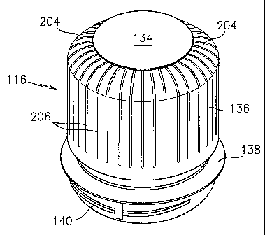
FIGS. 4= 5 show the improved cup 116 of the present invention which
advantageously is used as a closure for container 12 and as a measuring cup.
Similar to cup 16 in FIG. 2, cup 116 in FIGS. 4- 5 is generally cup shaped
with a
closed base or bottom wall 134, a depending skirt-like side wall 136 and an
open mouth
137 terminating in a lip 139. The exact dimension of the outwardly extending
lip 139
may vary, and in the embodiment shown in FIGS. 4 - 5 it is somewhat smaller
thaii lip 39
in the prior art embodiment of FIG. 2, but the function is the same. Also,
similar to cup
16, cup 116 is generally formed of a fairly dense polymer, as medium to high
density
polyethylene.
Cup 116 has an upper wall portion 200 surrounding open mouth 137 with
outwardly facing fastening means, as threads 140 on the upper wall portion to
cooperate
with the inwardly facing threads 58 of collar 14 in the prior art embodiment
of
FIGS. 1- 3. A coaxial shoulder 138 is located on the upper wall below threads
140
CA 02534395 2006-01-30
WO 2005/019034 PCT/US2004/004784
9
and spaced from lip 139, projecting outwardly from the exterior surface of the
upper wall
serving the same function as shoulder 38 in the prior art embodiment of FIG.
2.
However, in the present invention an outwardly extending connecting wall
portion 202 is provided connecting the side wall 136 with the upper wall 200.
Connecting wa11202 is outwardly oriented with respect to upper wa11200 at an
angle of
less than 90 , and generally at an angle of from 5 to 45 with respect to
upper wa11200.
As clearly shown in FIGS. 4- 5, the outward orientation of the connecting
wa11202
provides that the side wall 136, which is substantially larger than the upper
wa11200, is
disposed outwardly of the upper wall, providing an increased volume measuring
cup
without increasing the size of the upper wall portion. This enables container
116 to
desirably and advantageously have an increased volume than the prior art
measuring cup
at the same height and with the same upper wall size configuration. This
represents a
considerable advantage in the art since it is desirable to provide such
increased capacity
with the same height to accommodate market shelf configurations, and to
utilize the same
upper wall size configuration to accommodate existing products.
CA 02534395 2006-01-30
WO 2005/019034 PCT/US2004/004784
In the embodiment of FIGS. 4- 5, a curved or angled wall portion 204 is
provided connecting base 134 and side wall 136, and longitudinal striations
206 are
provided on the external surfaces of at least side wall 136 and preferably
also angled wall
204 to provide an aesthetically pleasing design.
The improved measuring cup of the present invention can be formed by direct
injection molding, or desirably by injection molding a prior art type
measuring cup and
using the resultant cup as a preform to form the cup of the present invention
by blow
molding. In the blow molded embodiment the upper wall portion would remain
unchanged from the injection molded configuration, and the preform would be
heated to
blow molding temperature in accordance with standard procedure.
The particular embodiment of FIGS. 4 - 5 is representative only. The side wall
portion could, if desired, be formed so that it is disposed outwardly of the
upper wall
portion an increased distance to provide a greater volume than that shown in
FIGS. 4- 5,
if desired, or a smaller distance to provide a lesser volume than that shown,
if desired.
It is to be understood that the invention is not limited to the illustrations
described
and shown herein, which are deemed to be merely illustrative of the best modes
of
carrying out the invention, and which are susceptible of modification of form,
size,
CA 02534395 2006-01-30
WO 2005/019034 PCT/US2004/004784
11
arrangement of parts and details of operation. The invention rather is
intended to
encompass all such modifications which are within its spirit and scope as
defined by the
claims.