Sélection de la langue

Search

Sommaire du brevet 2536749 

Énoncé de désistement de responsabilité concernant l'information provenant de tiers

Une partie des informations de ce site Web a été fournie par des sources externes. Le gouvernement du Canada n'assume aucune responsabilité concernant la précision, l'actualité ou la fiabilité des informations fournies par les sources externes. Les utilisateurs qui désirent employer cette information devraient consulter directement la source des informations. Le contenu fourni par les sources externes n'est pas assujetti aux exigences sur les langues officielles, la protection des renseignements personnels et l'accessibilité.

Disponibilité de l'Abrégé et des Revendications

L'apparition de différences dans le texte et l'image des Revendications et de l'Abrégé dépend du moment auquel le document est publié. Les textes des Revendications et de l'Abrégé sont affichés :

  • lorsque la demande peut être examinée par le public;
  • lorsque le brevet est émis (délivrance).
(12) Brevet: (11) CA 2536749
(54) Titre français: APPAREIL ET PROCEDE DE VISUALISATION D'OBJETS CIBLES DANS UN TUYAU TRANSPORTANT UN FLUIDE
(54) Titre anglais: AN APPARATUS AND A METHOD OF VISUALIZING TARGET OBJECTS IN A FLUID-CARRYING PIPE
Statut: Accordé et délivré
Données bibliographiques
(51) Classification internationale des brevets (CIB):
  • G01N 23/203 (2006.01)
  • E21B 47/12 (2012.01)
(72) Inventeurs :
  • TEAGUE, PHIL (Norvège)
  • RAMSTAD, EINAR (Norvège)
(73) Titulaires :
  • VISURAY TECHNOLOGY LTD
(71) Demandeurs :
  • VISURAY TECHNOLOGY LTD (Malte)
(74) Agent: NORTON ROSE FULBRIGHT CANADA LLP/S.E.N.C.R.L., S.R.L.
(74) Co-agent:
(45) Délivré: 2017-04-25
(86) Date de dépôt PCT: 2004-08-26
(87) Mise à la disponibilité du public: 2005-03-10
Requête d'examen: 2009-08-19
Licence disponible: S.O.
Cédé au domaine public: S.O.
(25) Langue des documents déposés: Anglais

Traité de coopération en matière de brevets (PCT): Oui
(86) Numéro de la demande PCT: PCT/NO2004/000252
(87) Numéro de publication internationale PCT: NO2004000252
(85) Entrée nationale: 2006-02-23

(30) Données de priorité de la demande:
Numéro de la demande Pays / territoire Date
20033832 (Norvège) 2003-08-29
20043504 (Norvège) 2004-08-23

Abrégés

Abrégé français

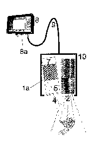
L'invention concerne un appareil permettant d'enregistrer et d'afficher des images de types de matériau dans un objet cible (3), et d'identifier ceux-ci, dans un tuyau transportant un fluide. L'appareil comprend une unité de fond de trou (10) possédant une source lumineuse (1) disposée de manière à émettre des photons à énergie élevée (2) et une unité de détection (1a) disposée de manière à enregistrer les photons (4) réfléchis à partir de l'objet cible (3). L'appareil comprend également une commande et une unité d'affichage (8) dotée de moyens de transmission de signal (9) et d'un écran de visualisation (8a). De plus, l'invention concerne un procédé d'enregistrement et d'affichage d'images de l'objet cible (3) mettant en oeuvre l'appareil.


Abrégé anglais


An apparatus for recording and displaying images of an identifying material
types in a target object (3) in a fluid carrying pipe, where the apparatus
comprises a downhole unit (10) provided with a light source (1) arranged to
emit high energy photons (2), and that the downhole unit (10) is further
provided with a sensor unit (1a) arranged to register photons (4) reflected
from the target object (3). The apparatus further comprises a control and
display unit (8) provided with a signal transmission means (9) and a viewing
screen (8a). Further, description a method of recording and displaying images
of a target object (3) through use of the apparatus, is also described.

Revendications

Note : Les revendications sont présentées dans la langue officielle dans laquelle elles ont été soumises.


11
CLAIMS
1. An apparatus for recording and displaying images of and identifying
material
types in a target object in a fluid carrying conduit, the apparatus
comprising:
a downhole unit including:
a controllable light source, the controllable light source structured to
emit high energy photons,
a sensor unit structured to detect the high energy photons that are
backscattered from the target object, the sensor unit including an image
registering device configured to generate cellular electronic charges in
response
to the detected high energy photons, wherein the sensor unit is further
structured to transmit two-dimensional image data signals based on the
cellular
electronic charges; and
a control and display unit that includes a signal transmitter and a
viewing screen structured to display at least one two-dimensional image that
is
generated using the two-dimensional image data signals from the sensor unit.
2. The apparatus of claim 1, wherein the controllable light source is
structured to
emit x-ray radiation.
3. The apparatus of claim 1, wherein the controllable light source is
structured to
emit gamma radiation.
4. The apparatus of claim 1, wherein the sensor unit further comprises:
a scatter limiting aperture; and
an amplifier unit.
5. The apparatus of claim 1, wherein the image registering device comprises a
charge coupled device.
6. The apparatus of claim 1, wherein the image registering device comprises a
photodiode assembly.
7. The apparatus of claim 1, wherein the control and display unit further
comprises:
a means for selecting imagery;
a connection to a material database; and
a processor for comparing imagery.

12
8. The apparatus of claim 1, wherein the signal transmitter comprises a signal
cable.
9. The apparatus of'claim 1, wherein the signal transmitter comprises a read
unit
for a computer storage device.
10.The apparatus of claim 1, wherein the sensor unit and light source are
structured such that an angle of the sensor unit relative to the light source
is
adjustable.
11.The apparatus of claim 10, wherein the control and display unit are
structured
to remotely control the angle of the sensor unit relative to the light source
when the downhole unit is positioned within the fluid carrying conduit and
when
the control and display unit is positioned outside the fluid carrying conduit.
12.The apparatus of claim 8, wherein the downhole unit is structured to be
connected to the control and display unit with the signal cable.
13.The apparatus of claim 1, wherein the at least one two-dimensional image is
generated after a predefined interval of time.
14.The apparatus of claim 1, wherein the downhole unit is connected to or
integrated in a downhole tool.
15.The apparatus of claim 1 wherein the signal transmitter comprises a power
cable.
16.The apparatus of claim 15 wherein the downhole unit is structured to be
connected to the control and display unit with the power cable.

Description

Note : Les descriptions sont présentées dans la langue officielle dans laquelle elles ont été soumises.


CA 02536749 2006-02-23
WO 2005/022133 PCT/N02004/000252
1
AN APPARATUS AND A METHOD OF VISUALIZING TARGET OBJECTS IN A
FLUID-CARRYING PIPE
This invention regards an apparatus and a method of providing
an accurate image of a target object in an exploration or
production well or in a pipeline carrying fluids such as
hydrocarbons or aqueous liquids, and provides the opportunity
of accurately determining which types of material said target
object is composed of.
Herein, the term "fluid" is taken to mean any form of liquid
lo and/or gas, separately or mixed.
The environment in exploration and production wells for oil
and gas generally prohibits the use of video cameras due to
the presence of saline solutions, mud, hydrocarbons and other
substances that prevent the passage of visible light.
Consequently there exists no apparatus capable of "seeing"
the targets under such conditions. The term "see" means
making image recordings that can be viewed by the human eye
on e.g. a viewing screen, immediately or at a later stage.
This very often results in time-consuming and costly
inspections of well formations and equipment, and also

CA 02536749 2006-02-23
WO 2005/022133 PCT/N02004/000252
2
fishing operations directed at the removal of unwanted
objects in exploration and production wells.
A system is known from US 6 078 867, which produces a three-
dimensional image of a borehole by means of a four-armed (or
more) downhole calliper and gamma rays.
From US 4 847 814 there is known a system for creating
three-dimensional images by using data from a scan of a
borehole carried out by use of a rotary acoustic transducer.
EP 1070970 describes a method of three-dimensional
lo reconstruction of a physical quantity from a borehole
comprising the creation of a three-dimensional image by
measuring a first physical quantity as a function of depth,
then to be compared with a second item.
WO 9935490 describes an apparatus and a method of depicting a
lined borehole by means of ultrasound.
From US 5 987 385 there is known an acoustic logging tool for
creating a peripheral image of a borehole or a well lining by
means of ultrasound generated by several
transmitters/receivers mounted substantially in the same
plane in the end piece of a drill string.
US 4 821 728 describes a three-dimensional imaging system for
representation of objects scanned by ultrasound.
US 3 564 251 describes the use of radioactive radiation to
establish information about the distance from the apparatus

= CA 02536749 2015-02-02
3
to the surroundings, e.g. a well wall, by creating a radial
graph centred on the centre of the apparatus.
Available radiation types range from radio waves via visible
light to gamma rays. The wavelength of long-wave radiation
in the form of radio waves (> 1x10⁻¹ m) is too great to make
it possible to create focused images that fulfil the
requirements made. Short-wave radiation in the form of gamma
rays (< lx10-11m) has a wavelength and an energy level that
gives sufficient image quality but require a radiation
source in the form of a radioactive material. This is out of
the question in the environments for which the invention is
intended. Rays having a wavelength between 1x10⁻⁸ m and 1x10
-
m have the desired effect both in terms of image quality
and the energy level for penetration of relevant fluids.
The object of the invention is to remedy the disadvantages
of prior art.
The apparatus comprises known and novel technology combined
in a novel manner with regard to sensors, electronics,
software and assembly.
The possibility of "seeing÷ in such environments is highly
advantageous in terms of fulfilling the requirements for
identification and localization of possible material damage
and/or undesirable objects that have been lost or are stuck
in the borehole.

CA 02536749 2006-02-23
WO 2005/022133 PCT/N02004/000252
4
Today the possibility of "seeing" in such an environment by
using a video camera is highly limited, due to the normal
mixture of substances in the well.
An apparatus according to the invention will make it possible
to provide images of downhole target objects. The invention
uses any form of high-energy photon sources to illuminate a
target object in order to create an image of the object.
Preferably use is made of a light source that emits high-
energy photons having a wavelength between 1x10-11 m (0.01
nanometres) and lx10-8 m (10 nanometres).
The apparatus of the invention may be integrated in various
types of downhole tools and make it possible to obtain visual
information during critical operations.
Preferably, the recorded measurement data are transmitted to
a control unit on a continuous basis, allowing the images to
be generated in near real time.
Alternatively the images may be obtained following a delayed
transmission of the recorded measurement data, either through
causing a suitable delay in the measurement data in a
continuous signal transmission, or by storing the measurement
data in a suitable medium for retrieval at a later time, e.g.
after retrieving the measuring apparatus from the measurement
area.
The apparatus of the invention provides the possibility of
collecting spectral energy information from the target
object. Consequently, this information may be compared with a
database containing known spectral analysis information for
the types of material in question.

CA 02536749 2006-02-23
WO 2005/022133 PCT/N02004/000252
The apparatus of the invention comprises components that are
required to generate images from a fluid-carrying pipe in
which known video camera technology can not be used due to
the inability of ordinary light to penetrate the fluid
5 contents of the pipe.
The principle of the apparatus and a method according to the
invention is to generate an image of a downhole target object
by producing high-energy photons which are subsequently
detected by bireflection from the surface and internal
lo structures of the target object. The photons have an energy
that allows transmission of said photons through materials
with a low electron density, such as mud, saline solutions,
hydrocarbons and more. The detected reflected photons are
converted into images that can be displayed on a viewing
screen.
The apparatus comprises the following principal components:
= A control unit on the surface
= A s ignal/power cable between the control unit on
the surface and a downhole unit.
= A downhole source and recording unit.
Alternatively the apparatus comprises the following principal
components:
= A downhole source and recording unit with
start/stop controlled by a time switch, pressure
sensor, hydroacoustic receiver or similar.

CA 02536749 2013-03-12
6
= A control unit on the surface.
According to a further broad aspect of the present
invention, there is provided an apparatus for recording and
displaying images of and identifying material types in a
target object in a fluid carrying conduit. The apparatus
comprises a downhole unit including controllable light
source. The controllable light source is structured to emit
high energy photons. A sensor unit is structured to detect
the high energy photons that are backscattered from the
n target object. The sensor unit includes an image registering
device configured to generate cellular electronic charges in
response to the detected high energy photons. The sensor
unit is further structured to transmit two-dimensional image
data signals based on the cellular electronic charges.
Further provided is a control and display unit that includes
a signal transmitter and a viewing screen structured to
display at least one two-dimensional image that is generated
using the two-dimensional image data signals from the sensor
unit.
The following describes a non-limiting example of a
preferred embodiment illustrated in the accompanying
drawing, in which:
Figure 1 shows a schematic diagram of an apparatus according
to the invention.

CA 02536749 2013-03-12
6a
A downhole unit 10 comprises a cooling unit (not shown), a
light source 1 and a sensor unit la consisting of a scatter
limiting aperture 5, a scintillator/amplifier unit 6 and a
charge coupled device (CCD) or a photodiode assembly (PDA)
7. The light source 1 produces high-energy photons 2 having
a wavelength greater than lx10-11 m (0.01 nanometres). These
illuminate a downhole target object 3. Photons that result
from bireflection 4 (i.e. reflection, decelerating
radiation, scatter and/or Compton scatter) from the electron
density of a downhole object 3 pass through the aperture 5
and interact with the surface of the scintillator/amplifier
unit 6. The resulting photons, the majority of which have
wave lengths of more than lx10-8 m (10 nanometres) due to the
effect of the scintillator on the incident reflected
radiation, interact with the cell composition of the CCD/PDA
7, producing a cellular electronic charge, the magnitude and
character of which are proportional to the intensity of the
spectral energy of the incoming photons 4.
The accumulated electronic charge that arises in the cells
of the CCD/PDA 7 is collected in a holding buffer in the CCD
7, where the individual cellular electronic potentials are
temporarily stored. The content of the buffer is then
transmitted through a control/power cable 9 to a surface
mounted control and display unit 8 where a raster image is

CA 02536749 2006-02-23
WO 2005/022133
PCT/N02004/000252
7
displayed on a viewing screen 8a. The process is continuous,
with the CCD 7 being sampled and cleared several times per
second.
The angle of the sensor unit la relative to the source 1 can
be adjusted from the control and display unit 8 on the
surface in order to determine the distance to the target
object.
Any overall attenuation caused by high energy photons
interacting with downhole fluids such as saline solutions,
lo mud and hydrocarbons, can be filtered from the displayed
image, either by increasing the clearing rate from the CCD 7
or through processing the image on the surface by means of
the control and display unit 8.
The apparatus also provides the possibility of gathering
spectral energy information from the incoming photons 4. The
photons 4 carry information regarding the electron energy
level of the atoms in the target object 3. Consequently, the
distribution and magnitude of the received energy spectra can
be processed versus spectra from a database for relevant
types of material, these data being stored in the control and
display unit 8 or possibly in an external data storage unit
(not shown) that communicates with the control and display
unit 8. The selection of the image area that is to be
subjected to data comparison is carried out with appropriate,
previously known means (not shown).
Prior art offers the operators of well inspection equipment
few opportunities for receiving accurate visual feedback from
the hole. In consequence, most operations are carried out
blind, which is time consuming and entails a higher risk of

CA 02536749 2006-02-23
WO 2005/022133 PCT/N02004/000252
8
material damage. In extreme cases the contents of the well
must be removed and replaced with fluids that give better
visibility for a video camera, which increases the overall
cost of the well.
The apparatus provides the operator with direct visual
feedback without requiring any disturbances in the condition
of the well (i.e. displacement of fluid and cleaning).
Accordingly, use of the apparatus will entail a great
reduction in labour and cost with a view to intervention
lo operations. The possibility of receiving quick and realistic
feedback represents an important advantage over prior art.
The apparatus also provides the possibility of gathering
spectral energy information from the incoming photons 4.
These photons 4 contain information regarding the electronic
energy level of the atoms in the target object. Thus, the
acquired data can be compared with known material data. This
means that an operator of the equipment according to the
invention can point and click on the target object such as it
appears in the generated images and by so doing, obtain
information regarding the material to be examined, such as
scale (contamination), reservoir structure inspection, the
effect of perforations and more.
Such information may be of inestimable value to operators who
wish to know the composition of such materials without having
to bring them up to the surface for a closer examination and
laboratory testing. This may also be of particular benefit
prior to a scale clean-up, where the likelihood of
radioactive scale residue being brought to the surface is
high. The apparatus allows such scale to be examined prior to
cleaning up, so that the operator can prepare the receiving
area in accordance with the nature of the material.

CA 02536749 2006-02-23
WO 2005/022133
PCT/N02004/000252
9
As a result of the nature of the apparatus and the
possibility of creating images through downhole liners, the
apparatus may obviously also be used to see behind liner
walls.
In many instances, items are dropped or become jammed in the
wellbore during intervention and drilling operations. Known
pull-out or extraction technique comprises the use of an
indicator block that is conveyed into the hole to press
against the dropped or jammed item in order to obtain an
lo imprint of the top surface of the item. Examination of the
imprint on the indicator block allows the operator to select
the most appropriate gripping tool for extracting the item.
The apparatus of the invention can quickly provide a dynamic
image of the object, which offers advantageous information
such as specific identification, the interface dimensions of
the target object, contaminating deposits, possible damage to
the well structure and the well conditions. Due to its
flexibility the apparatus may also be integrated into or
coupled directly to the pull-out tool, thus allowing
identification and pull-out to be accomplished in a single
operation.
The apparatus of the invention may be used actively in
fishing operations where items require either activation or
extraction to the surface. Thus the apparatus allows
considerable advantages in terms of costs and safety, and
provides the operator with the possibility of receiving
visual feedback on the execution of the operation. Therefore
the risk of material damage will be reduced, while the speed
at which the operation is carried out can be increased.

CA 02536749 2006-02-23
WO 2005/022133
PCT/N02004/000252
The apparatus may be used as a means of conveyance in order
to carry other sensors such as temperature, pressure and flow
sensor assemblies, thus forming a downhole diagnostic tool.

Dessin représentatif
Une figure unique qui représente un dessin illustrant l'invention.
États administratifs

2024-08-01 : Dans le cadre de la transition vers les Brevets de nouvelle génération (BNG), la base de données sur les brevets canadiens (BDBC) contient désormais un Historique d'événement plus détaillé, qui reproduit le Journal des événements de notre nouvelle solution interne.

Veuillez noter que les événements débutant par « Inactive : » se réfèrent à des événements qui ne sont plus utilisés dans notre nouvelle solution interne.

Pour une meilleure compréhension de l'état de la demande ou brevet qui figure sur cette page, la rubrique Mise en garde , et les descriptions de Brevet , Historique d'événement , Taxes périodiques et Historique des paiements devraient être consultées.

Historique d'événement

Description Date
Paiement d'une taxe pour le maintien en état jugé conforme 2023-09-26
Inactive : TME en retard traitée 2023-09-26
Représentant commun nommé 2019-10-30
Accordé par délivrance 2017-04-25
Inactive : Page couverture publiée 2017-04-24
Préoctroi 2017-03-06
Inactive : Taxe finale reçue 2017-03-06
Un avis d'acceptation est envoyé 2017-01-06
Lettre envoyée 2017-01-06
Un avis d'acceptation est envoyé 2017-01-06
Inactive : Approuvée aux fins d'acceptation (AFA) 2016-12-19
Inactive : Q2 réussi 2016-12-19
Modification reçue - modification volontaire 2016-06-06
Inactive : Dem. de l'examinateur par.30(2) Règles 2015-12-04
Inactive : Rapport - CQ réussi 2015-12-02
Retirer de l'acceptation 2015-11-30
Inactive : Approuvée aux fins d'acceptation (AFA) 2015-10-02
Inactive : Q2 réussi 2015-10-02
Inactive : CIB en 1re position 2015-05-29
Inactive : CIB enlevée 2015-05-29
Inactive : CIB attribuée 2015-05-29
Inactive : CIB attribuée 2015-05-28
Modification reçue - modification volontaire 2015-02-02
Inactive : Dem. de l'examinateur par.30(2) Règles 2014-11-04
Inactive : Rapport - Aucun CQ 2014-10-28
Inactive : Demande ad hoc documentée 2014-06-05
Modification reçue - modification volontaire 2014-04-10
Inactive : Dem. de l'examinateur par.30(2) Règles 2013-12-27
Inactive : Rapport - Aucun CQ 2013-12-19
Lettre envoyée 2013-04-11
Inactive : Transfert individuel 2013-03-15
Modification reçue - modification volontaire 2013-03-12
Inactive : Dem. de l'examinateur par.30(2) Règles 2012-11-06
Inactive : CIB expirée 2012-01-01
Inactive : CIB enlevée 2011-12-31
Lettre envoyée 2009-09-30
Modification reçue - modification volontaire 2009-08-19
Exigences pour une requête d'examen - jugée conforme 2009-08-19
Toutes les exigences pour l'examen - jugée conforme 2009-08-19
Requête d'examen reçue 2009-08-19
Inactive : Lettre officielle 2008-10-14
Inactive : Correspondance - Transfert 2008-06-26
Lettre envoyée 2008-02-11
Inactive : Transfert individuel 2007-12-03
Lettre envoyée 2006-08-17
Inactive : Transfert individuel 2006-06-22
Inactive : Page couverture publiée 2006-05-02
Inactive : Lettre de courtoisie - Preuve 2006-05-02
Inactive : Notice - Entrée phase nat. - Pas de RE 2006-04-27
Demande reçue - PCT 2006-03-16
Exigences pour l'entrée dans la phase nationale - jugée conforme 2006-02-23
Demande publiée (accessible au public) 2005-03-10

Historique d'abandonnement

Il n'y a pas d'historique d'abandonnement

Taxes périodiques

Le dernier paiement a été reçu le 2016-07-14

Avis : Si le paiement en totalité n'a pas été reçu au plus tard à la date indiquée, une taxe supplémentaire peut être imposée, soit une des taxes suivantes :

  • taxe de rétablissement ;
  • taxe pour paiement en souffrance ; ou
  • taxe additionnelle pour le renversement d'une péremption réputée.

Les taxes sur les brevets sont ajustées au 1er janvier de chaque année. Les montants ci-dessus sont les montants actuels s'ils sont reçus au plus tard le 31 décembre de l'année en cours.
Veuillez vous référer à la page web des taxes sur les brevets de l'OPIC pour voir tous les montants actuels des taxes.

Titulaires au dossier

Les titulaires actuels et antérieures au dossier sont affichés en ordre alphabétique.

Titulaires actuels au dossier
VISURAY TECHNOLOGY LTD
Titulaires antérieures au dossier
EINAR RAMSTAD
PHIL TEAGUE
Les propriétaires antérieurs qui ne figurent pas dans la liste des « Propriétaires au dossier » apparaîtront dans d'autres documents au dossier.
Documents

Pour visionner les fichiers sélectionnés, entrer le code reCAPTCHA :


Pour visualiser une image, cliquer sur un lien dans la colonne description du document (Temporairement non-disponible). Pour télécharger l'image (les images), cliquer l'une ou plusieurs cases à cocher dans la première colonne et ensuite cliquer sur le bouton "Télécharger sélection en format PDF (archive Zip)" ou le bouton "Télécharger sélection (en un fichier PDF fusionné)".

Liste des documents de brevet publiés et non publiés sur la BDBC .

Si vous avez des difficultés à accéder au contenu, veuillez communiquer avec le Centre de services à la clientèle au 1-866-997-1936, ou envoyer un courriel au Centre de service à la clientèle de l'OPIC.

({010=Tous les documents, 020=Au moment du dépôt, 030=Au moment de la mise à la disponibilité du public, 040=À la délivrance, 050=Examen, 060=Correspondance reçue, 070=Divers, 080=Correspondance envoyée, 090=Paiement})


Description du
Document 
Date
(aaaa-mm-jj) 
Nombre de pages   Taille de l'image (Ko) 
Dessins 2006-02-22 1 48
Description 2006-02-22 10 379
Revendications 2006-02-22 4 106
Abrégé 2006-02-22 2 85
Dessin représentatif 2006-02-22 1 46
Description 2013-03-11 11 414
Revendications 2013-03-11 2 61
Revendications 2014-04-09 2 60
Description 2015-02-01 11 405
Revendications 2015-02-01 2 59
Dessin représentatif 2017-03-21 1 15
Avis d'entree dans la phase nationale 2006-04-26 1 206
Courtoisie - Certificat d'enregistrement (document(s) connexe(s)) 2006-08-16 1 105
Courtoisie - Certificat d'enregistrement (document(s) connexe(s)) 2008-02-10 1 108
Courtoisie - Certificat d'enregistrement (document(s) connexe(s)) 2008-02-10 1 105
Rappel - requête d'examen 2009-04-27 1 117
Accusé de réception de la requête d'examen 2009-09-29 1 175
Courtoisie - Certificat d'enregistrement (document(s) connexe(s)) 2013-04-10 1 103
Avis du commissaire - Demande jugée acceptable 2017-01-05 1 164
Courtoisie - Réception du paiement de la taxe pour le maintien en état et de la surtaxe (brevet) 2023-09-25 1 420
Paiement de taxe périodique 2023-09-25 1 29
PCT 2006-02-22 8 333
Correspondance 2006-04-26 1 28
Correspondance 2008-10-13 1 9
Demande de l'examinateur 2015-12-03 5 284
Modification / réponse à un rapport 2016-06-05 4 166
Taxe finale 2017-03-05 2 76