Note : Les descriptions sont présentées dans la langue officielle dans laquelle elles ont été soumises.
CA 02548960 2006-06-09
WO 2005/064983 PCT/EP2003/014800
1
SYSTEM AND METHOD FOR THE AUTOMATIC SETUP OF SWITCHED
CIRCUITS BASED ON TRAFFIC PREDICTION IN A TELECOMMUNICATIONS
NETWORK
The present invention relates to a system and a method for an automatic set-up
and tear down of switched circuits based on the monitoring and/or forecasting
of
the ingress packet traffic in nodes of a telecommunications network.
TDM (Time Division Multiplexing) transport networks (e.g. SDH) have been
basically designed for voice and leased line services. In the last years many
network operators have largely deployed SDH transport platforms in both long
haul and metropolitanlregional networks. However, today it is widely
recognized
that traffic on transport networks will be progressively dominated by data
traffic
(especially Internet-based), with respect to traditional voice traffic, due to
a
progressive migration of many applications and services over the Internet
Protocol
(IP), and thanks to the introduction of high-speed access technology. The
introduction of WDM (Wavelength Division Multiplexing) or DWDM (Dense
Wavelength Division Multiplexing) optical point-to-point systems is already
providing high capacity links in order to cope with the growing of the traffic
demands. On the other hand, the statistical characteristics of this growing
data
traffic (especially IP traffic) are rather different from those of traditional
voice traffic.
As a whole, IP traffic is not easily predictable and stable as the traditional
voice
traffic. in turn, IP traffiic may show unpredictable traffic bursts.
Consequently, main
requirements for new-generation transport networks include flexibility and
ability to
react to traffic demand changes with time. Another key issue relates to the
fact
that even though the data traffic (especially Internet traffic) is becoming
dominant,
it does not generate revenue as do valuable voice services. Practically, this
means
that if a network was upgraded by adding bandwidth and expanding
infrastructure
in proportion to the amount of data traffic increase, the revenues would be
smaller
than the overall costs. For this reasons, network operators are seeking both
to
accommodate increasing bandwidth demands for data traffic and to dynamically
provide optical connections, trying to make an optimal use of the available
network
resources and saving operating costs. For example, simply dimensioning a
transport network to cope with data traffic bursts could be inefficient and
expensive.
CONFIRMATION COPY
CA 02548960 2006-06-09
WO 2005/064983 PCT/EP2003/014800
2
Traffic engineering (TE) is the process to control traffic flows in a network
in order
to optimize resource use and network performance. Practically, this means
choosing routes taking into account traffic load, network state, and user
requirements such as Quality of Service (QoS) or bandwidth, and moving traffic
from more congested paths to less congested ones.
In order to achieve TE in an Internet network context, the Internet
Engineering
Task Force (IETF) has introduced MPLS (Multi Protocol Label Switching). The
MPLS scheme is based on the encapsulation of IP packets into labeled packets
that are forwarded in a MPLS domain along a virtual connection called label
switched path (LSP). MPLS routers are called label switched routers (LSRs),
and
the LSRs at the ingress and egress of a MPLS domain are called edge LSRs (E-
LSRs). Each LSP can be set up at the ingress LSR by means of ordered control
before packet forwarding. This LSP can be forced to follow a route that is
calculated a priori thanks to the explicit routing function. Moreover, MPLS
allows
the possibility to reserve network resources on a specific path by means of
suitable signaling protocols. In particular, each LSP can be set up, torn
down,
rerouted if needed, and modified by means of the variation of some of its
attributes. Furthermore, preemption mechanisms on LSPs can also be used in
order to favor higher-priority data flows at the expense of lower-priority
ones, while
avoiding congestion in the network.
To extend the features of the MPLS technique, a generalized version of the
same
has also been proposed, known as GMPLS. GMPLS encompasses time-division
(e.g. SONET/SDH, PDH, G.709), wavelength, and spatial switching (e.g. incoming
port or fiber to outgoing port or fiber). The establishment of LSPs that span
only
Packet Switch Capable (PSC) or Layer-2 Switch Capable (L2SC) interfaces is
defined for the MPLS and/or MPLS-TE control planes. GMPLS extends these
control planes to support all the interfaces (i.e. layers): Packet Switch
Capable
(PSC) interfaces, Layer-2 Switch Capable (L2SC) interfaces, Time-Division
Multiplex Capable (TDM) interfaces, ~.-Switch Capable (LSC) interfaces, Fiber-
Switch Capable (FSC) interfaces. According to current standards, the GMPLS
control plane can support three models: overlay, augmented and a peer
CA 02548960 2006-06-09
WO 2005/064983 PCT/EP2003/014800
3
(integrated) models. These models are differentiated based on the amount of
routing/topological information exchanged between the layer networks.
P. lovanna, R. Sabella, M. Settembre, in the article "A Traffic Engineering
System
for Multilayer Networks Based on the GMPLS Paradigm", IEEE Network, March-
April 2003, pag.28-35, propose a traffic engineering system able to
dynamically
react to traffic changes while at the same time fulfilling QoS requirements
for
different classes of service. The solution by the authors consists of a hybrid
routing
approach, based on both offline methods and online methods, and a bandwidth
management system that handles priority, preemption mechanisms, and traffic
rerouting in order to concurrently accommodate the largest amount of traffic
and
fulfill QoS requirements. More specifically, the TE system invokes an offline
procedure to achieve global optimization of path calculation, according to an
expected traffic matrix, while invoking an online routing procedure to
dynamically
accommodate, sequentially, actual traffic requests, allowing reaction to
traffic
changes. The building blocks of the TE system are: a path provisioning module,
a
dynamic provisioning module, a bandwidth engineering module. The path
provisioning module calculates offline the routes for all foreseen
connections,
according to a traffic matrix that describes the traffic relationships between
each
network node pair, on the basis of the physical topology of the network and
information about network resources (e.g., presence of wavelength conversion
inside optical cross connects, link capacity). The dynamic routing module
evaluates the route for a single LSP request at a time, expressed in terms of
source and destination nodes and bandwidth requirements. Basically, the
dynamic
routing algorithm finds a route aimed at better utilizing network resources by
using
less congested paths instead of shortest, but heavily loaded paths. The TE
system
is based on elastic use of bandwidth: the bandwidth can be temporary released
by
higher priority LPSs and put at disposal of all the lower priority LPSs. This
can be
done provided that the bandwidth is immediately given back to high priority
traffic
as soon as needed. When a higher priority LSP requires more bandwidth and at
least one link on its path is congested, the bandwidth engineering module is
invoked to make the required bandwidth available. The bandwidth engineering
module can be represented by a preemption module that tears down all the LSPs
whose priority level is lower than that of the LSP to be accommodated.
CA 02548960 2006-06-09
WO 2005/064983 PCT/EP2003/014800
4
A. Gen~ata and B. Mukherjee, in the article "Virtual-Topology Adaptation for
WDM
Mesh Networks Under Dynamic Traffic", IEEE/ACM Transactions on Networking,
Vo1.11, No.2, April 2003, pag.236-247, propose an approach for the virtual-
topology reconfiguration problem for a WDM based optical wide-area mesh
network under dynamic traffic demand. The key idea of the authors' approach is
to
adapt the underlying optical connectivity by measuring the actual traffic load
on
lightpaths continuously (periodically based on a measurement period), and
reacting promptly to the load imbalances caused by fluctuations on the
traffic, by
either adding or deleting one or more lightpaths at a time. When a load
imbalance
is encountered, it is corrected either by tearing down a lightpath that is
lightly
loaded or by setting up a new lightpath when congestion occurs.
US patent application no.2003/0067880 discloses a system and a method of
implementing Routing Stability-Based Integrated Traffic Engineering for use in
an
MPLS/optical network. Incoming network traffic is classified as high priority,
which
can tolerate limited rerouting. In accordance with one embodiment, high
priority
traffic trunks are mapped onto direct light channels (or LSPs) and rerouted
only in
the event of a light channel tear down due to poor traffic utilization.
According to
the applicant of '880 patent application, a direct light channel, or LSP, is
one that
comprises a direct optical connection between an ingress/egress node pair via
one
or more OXCs. Low priority traffic trunks are mapped onto direct light
channels if
available; otherwise, they are mapped onto multi-hop LSPs with appropriate
optical/electrical/optical conversions at the edge nodes serving as
intermediate
hops. According to the applicant of '880 patent application, a multi-hop light
channel, or LSP, is one that constitutes more than one light channel and hence
comprises an optical connection between an ingress/egress node pair via one or
more OXCs and one or more edge nodes other than the ingress/egress nodes.
The optical/electrical/optical conversions at the intermediate nodes may
introduce
packet delays for the traffic mapped onto multi-hop LSPs. Each such low
priority
traffic trunk is associated with a rerouting timer that is set at the time of
rerouting,
so as to prevent another rerouting of the trunk until the timer expires.
The Applicant has found that in order to cope with the dynamic changes in the
data traffic demand, a management of the switched circuits (e.g. lightpaths of
a
WDM network and/or TDM circuits of a circuit-switched network, such as a
CA 02548960 2006-06-09
WO 2005/064983 PCT/EP2003/014800
SDH/SONET network) available at a "server" layer in an optical transport
network
advantageously allows to keep limited the size of the network.
According to the Applicant, the problem of coping with the dynamic changes in
the
5 data traffic demand can be solved, maintaining a limited size of the
network, by
concentrating the attention on high priority (i.e. "premium") traffic.
Resources are
dedicated at a circuit "server" layer (e.g. lightpaths and/or TDM circuits) to
high
priority traffic, in addition to the resources dedicated at the electronic
packet
"client" layer (e.g. LSPs, portions of LSP bandwidth, interfaces). More
particularly,
the Applicant has found that by configuring an optical network in advance so
as to
dedicate a first portion of switched circuits (e.g. lightpaths and/or TDM
circuits) to
high priority traffic, and leaving a second portion of switched circuits
available for
low priority traffic, the problem of coping with traffic bursts can be solved
by
monitoring the high priority traffic entering the high priority switched
circuits. In
case of detection of a burst in high priority traffic, at least one of the low
priority
switched circuit can be torn down, so as to make available network resources
within the network. Then, a new temporary switched circuit is set up using the
network resources made available after the tearing down of the low priority
switched circuit, and high priority traffic is routed on the new temporary
switched
circuit.
In a first aspect, the invention relates to a method of managing traffic in an
optical
network. The method comprises:
- tagging a first portion of traffic in ingress to at least one node of said
network
as high priority traffic and a second portion of traffic in ingress to said at
least
one node as low priority traffic;
- configuring at least a portion of said network so that a first portion of
switched
circuits exiting from said at least one node is adapted to carry said high
priority
traffic and a second portion of switched circuits exiting from said at least
one
node is adapted to carry said low priority traffic;
- detecting a burst of said high priority traffic;
- after said step of detecting said burst, acting on at least a portion of
said low
priority traffic, so as to deplete at least one interface of said at least one
node,
connected to at least one switched circuit of said second portion of switched
circuits;
CA 02548960 2006-06-09
WO 2005/064983 PCT/EP2003/014800
6
tearing down at least one switched circuit connected to said at least one
depleted node interface;
- setting up at least one new temporary switched circuit starting from said at
least one depleted node interface;
- forwarding a portion of said high priority traffic to said at least one
depleted
node interface, and, thereby, to said new temporary switched circuit.
The step of detecting a burst preferably comprises:
- estimating a first bandwidth of said high priority traffic in a first
predetermined
time interval;
- comparing said first bandwidth with a first predetermined threshold.
The step of acting on at least a portion of low priority traffic is preferably
carried
out if said first bandwidth exceeds said first predetermined threshold.
The step of estimating said first bandwidth preferably comprises:
- measuring a bandwidth of said high priority traffic in a second
predetermined
time interval;
- forecasting said first bandwidth in said first time interval from said
measured
bandwidth.
The method may further comprise a step of detecting an end of said high
priority
traffic burst.
Said step of detecting an end of said high priority traffic burst may
comprise:
- estimating a second bandwidth of said high priority traffic in a third
predetermined time interval;
- comparing said second bandwidth with a second predetermined threshold.
The step of estimating said second bandwidth may preferably comprise:
- measuring a bandwidth of said high priority traffic in a fourth
predetermined
time interval;
- forecasting said second bandwidth in said third time interval from said
measured bandwidth.
CA 02548960 2006-06-09
WO 2005/064983 PCT/EP2003/014800
7
Typically, said first threshold is higher than or equal to said second
threshold.
The method may further comprise:
- after said step of detecting said end of burst, acting on said forwarded
portion
of said high priority traffic, so as to route said forwarded portion towards
at
least one switched circuit of said first portion of switched circuits;
- tearing down said at least one new temporary switched circuit;
- restoring said at least one torn down switched circuit of said second
portion of
switched circuits.
The step of acting on said forwarded portion of said high priority traffic may
be
carried out if said second predetermined threshold exceeds said second
bandwidth.
In a second aspect, the invention relates to an optical network comprising at
least
one node and at least one network controller, wherein:
- said at least one node comprises a router adapted to tag a first portion of
traffic
in ingress thereof as high priority traffic and a second portion of traffic in
ingress thereof as low priority traffic;
- said network controller is adapted to configure at least a portion of said
network in order to have a first portion of switched circuits exiting from
said at
least one node adapted to carry said high priority traffic and a second
portion
of switched circuits exiting from said at least one node adapted to carry said
low priority traffic;
- said network controller also comprises a traffic controller adapted to
detect a
burst of said high priority traffic and to thereby send a first warning
signal;
- said router is also adapted to act on at least a portion of said low
priority traffic
in case of receipt of said first warning signal, so as to deplete at least one
node
interface, connected to at least one switched circuit of said second portion
of
switched circuits;
- said network controller is also adapted to tear down at least one switched
circuit connected to said depleted node interface, in case of receipt of said
first
warning signal;
- said network controller is also adapted to set up at least one new temporary
switched circuit starting from said at least one depleted node interface;
CA 02548960 2006-06-09
WO 2005/064983 PCT/EP2003/014800
8
- said router is also adapted to forward a portion of said high priority
traffic to
said at least one depleted node interface, and, thereby, to said new temporary
switched circuit.
The traffic controller is preferably adapted to:
- estimate a first bandwidth of said high priority traffic in a first
predetermined
time interval;
- compare said first bandwidth with a first predetermined threshold.
The traffic controller may be also adapted to send said first warning signal
if said
first bandwidth exceeds said first predetermined threshold.
The traffic controller may be also adapted to:
- measure a bandwidth of said high priority traffic in a second predetermined
time interval;
- forecast said first bandwidth in said first time interval from said measured
bandwidth.
The traffic controller may be also adapted to detect an end of said high
priority
traffic burst and thereby to send a second warning signal.
The traffic controller may be also adapted to:
- estimate a second bandwidth of said high priority traffic in a third
predetermined time interval;
- compare said second bandwidth with a second predetermined threshold.
The traffic controller may be also adapted to:
- measure a bandwidth of said high priority traffic in a fourth predetermined
time
interval;
- forecast said second bandwidth in said third time interval from said
measured
bandwidth.
Typically, said first threshold is higher than or equal to said second
threshold.
The optical network of the invention may also be configured so as:
CA 02548960 2006-06-09
WO 2005/064983 PCT/EP2003/014800
9
- said router is also adapted to act on said forwarded portion of said high
priority
traffic in case of receipt of said second warning signal, so as to route said
forwarded portion towards at least one switched circuit of said first portion
of
switched circuits;
- said network controller is also adapted to tear down said at least one new
temporary switched circuit, in case of receipt of said second warning signal;
- said network controller is also adapted to restore said at least one torn
down
switched circuit of said second portion of switched circuits, in case of
receipt of
said second warning signal.
Typically, said at least one node comprises a switching equipment.
The switching equipment may comprise a digital cross connect, or an optical
cross
connect, or an add/drop multiplexer, or a fiber switch.
Typically, optical fibers are connected to said switching equipment.
Further features and advantages of the invention will be made apparent by the
following detailed description of some embodiments thereof, provided merely by
way of non-limitative examples, description that will be conducted making
reference to the attached drawings, wherein:
- Figure 1 schematically shows a portion of an exemplary IP/MPLS over optical
network configured according to the invention, in case of normal high priority
traffic flows;
- Figure 2 schematically shows a step of bundling high priority LSPs into high
priority lightpaths, and low priority LSPs into low priority lightpaths;
- Figure 3 schematically shows the portion of optical network of fig.1 re-
configured according to an embodiment of the invention, during a burst of high
priority traffic;
- Figure 4 schematically shows a step of comparing an estimated bandwidth of
high priority traffic with pre-selected bandwidth thresholds;
- Figure 5 shows an exemplary daily high priority traffic evolution;
- Figure 6 shows the result of a simulation test obtained using the daily high
priority traffic evolution shown in fig.5;
CA 02548960 2006-06-09
WO 2005/064983 PCT/EP2003/014800
- Figure 7 shows, in a schematized view, different possible "server" layer
segmentations that may be used by a "client" packet network;
- Figure 8 schematically shows a network node using two nested "server" layers
connected to a client layer.
5
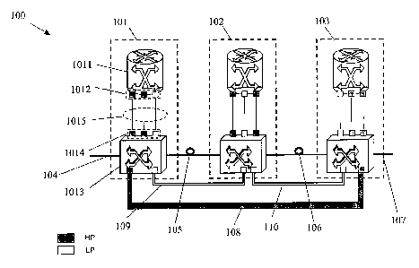
Fig.1 shows a portion of an IP/MPLS over WDM or DWDM optical network 100
configured according to the invention, comprising three nodes 101, 102, 103,
connected to each other (and to other nodes of the network) by optical fibers
104,
105, 106, 107. It has to be understood that the expression "optical fibers"
may
10 comprise one or more optical fibers, typically bundled together in one or
more
optical cables. In preferred embodiments, the network 100 has automatic
switching capabilities. More particularly, each node 101, 102, 103 comprises
equipment adapted for adding, and/or dropping, and/or routing optical signals
onto
the optical fibers 104, 105, 106, 107. In a WDM or DWDM network such optical
signals typically comprise optical carriers, or channels, having predetermined
wavelengths (e.g. in a wavelength range around 1550 nm), onto which an
information-carrying signal is added, at a predetermined frequency (e.g. in a
range
from several Mbit/s to several Gbit/s).
With reference to node 101, the node equipment comprises a router 1011, for
example an IP/MPLS router, adapted for providing and/or receiving the
information-carrying signal to be added and/or discriminated from the
respective
optical carrier. For this purpose, the router 1011 has respective interfaces
1012.
The node 101 further comprises a switching equipment 1013, such as a digital
cross connect (DXC), an optical cross connect (OXC), an add/drop multiplexer
(OADM), or a fiber switch, adapted for adding to the optical fibers 104, 105
the
optical signals originated from node 101, and/or for dropping from the optical
fibers
104, 105 the optical signals to be terminated (i.e. received) in node 101,
and/or for
routing from optical fiber 104 to optical fiber 105 (and/or vice-versa) the
optical
signals having origin and/or destination different from node 101. Typically,
the
switching equipment 1013 comprises a switching matrix adapted for switching
the
incoming optical signals according to a predetermined routing table. The
switching
equipment 1013 may further comprise a number of wavelength converters.
Furthermore, it has respective interfaces 1014 connected by suitable
connections
1015 to the interfaces 1012 of the router 1011. The router 1011 is either
CA 02548960 2006-06-09
WO 2005/064983 PCT/EP2003/014800
11
connected to or integrated with the switching equipment 1013, at the
discretion of
manufacturers and network operators. In a typical multi-layer scheme, the
router
1011 acts as a "client" layer of the "server" transport layer represented by
the
switching device 1013 and by the optical fibers 104, 105. It has to be
understood
that the other nodes 102, 103 include equipment similar to node 101, that will
not
be described for the sake of simplicity and clarity of fig.1. Fig.1 further
shows three
lightpaths, i.e. three end-to-end switched optical connections, established
between
nodes 101, 102, 103: more particularly, a first lightpath 108 is established
between
nodes 101 and 103, a second lightpath 109 is established between nodes 101 and
102, a third lightpath 110 is established between nodes 102 and 103.
Incoming traffic from router 1011 is split in high priority and low priority
traffic at the
"client" layer. This classification may be carried out based on a service
level
agreement (SLA), for example regulating a guarantee of a predetermined level
of
quality of service (QoS). Typically, the high priority traffic is the source
of higher
revenue for the network operator. It has to be understood that a number of
priority
levels higher than two may be provided. For example, in an IP/MPLS context,
LSPs may be tagged as high priority and low priority within the router 1011.
According to the invention, the network 100 is configured by one or more
network
controllers so as to dedicate separate resources also at the "server" optical
layer
to high priority traffic and to low priority traffic. More particularly, the
lightpaths are
also classified as high priority lightpaths and low priority lightpaths: high
priority
lightpaths are selected to carry high priority traffic, whereas low priority
lightpaths
are selected to carry low priority traffic, as schematically shown in fig.2.
However,
it has not to be excluded that low priority traffic could travel along
lightpaths tagged
as high priority lightpaths, during periods of underutilization by high
priority traffic.
The network controller may be either centralized or distributed. In order to
accomplish the "ordered" arrangement of the lightpaths, the interfaces of the
router
1011 and of the switching equipment 1013 are also tagged as high priority
interfaces and low priority interfaces. As a guideline for classification in
"high
priority" and "low priority" of the lightpaths, routing characteristics (e.g.
path length,
number of crossed nodes) and/or survivability policies (e.g. protection,
restoration,
no protection etc.) can be taken into account.
CA 02548960 2006-06-09
WO 2005/064983 PCT/EP2003/014800
12
The above arrangement of the network 100 is schematically shown in Fig.1 by a
different grayscale of the resources dedicated to high priority and to low
priority
traffic, both at the "client" layer and at the "server" layer. As it can be
seen, the first
lightpath 108 between nodes 101 and 103 is tagged as high priority, whereas
the
second and third lightpaths 109, 110 between nodes 101 and 102 and between
nodes 102 and 103 are tagged as low priority. Furthermore, a number of router
and switching equipment interfaces are also tagged according to above
classification.
According to the invention, the so configured network 100 is capable to
promptly
react to traffic bursts of high priority traffic. In case of possible high
priority traffic
congestion, at least one low priority lightpath is torn down, thus making
available
new resources for the "excess" high priority traffic, at least for a limited
period of
time. In order to implement this method, at least one router interface
allocated to
low priority traffic (together with the corresponding switching equipment
interface) ._
is depleted from low priority traffic. This could correspond to a re-
distribution of the
low priority traffic previously carried by the depleted interface to another
low
priority interface (or to more than one interface) connected to lightpath(s)
towards
the same destination, if a sufficient bandwidth level is available for low
priority
traffic. On the contrary, if the available bandwidth level for low priority
traffic is not
sufficient, the excess low priority traffic is dropped. After depletion of a
sufficient
number of low priority node interfaces, the same interfaces are temporarily
tagged
as high priority, and the excess high priority traffic is re-distributed
through such
temporary high priority interfaces. Low priority lightpaths corresponding to
the
depleted interfaces are torn down, so as to make available resources (e.g.
fibers,
optical channels) within the network, ready to be temporary used for setting
up
new connection requests needed for coping with the high priority traffic
burst.
The above steps do not exclude that other attempts could be made before
tearing .;
down a low priority lightpath. For example, if low priority traffic flows in a
high
priority lightpath due to previous underutilization, low priority traffic
bandwidth may
be preempted in favor of the high priority traffic. If it is not enough, a re-
distribution
of the high priority traffic may be attempted using already established high
priority
lightpaths towards the same destination; a further attempt can be made in
order to
identify a possible low priority lightpath towards the same destination that
has
CA 02548960 2006-06-09
WO 2005/064983 PCT/EP2003/014800
13
appropriate characteristics to be "transformed", at least temporarily, in a
high
priority lightpath, i.e. to be depleted from low priority traffic in favor of
high priority
traffic.
A possible congestion due to high priority traffic burst may be determined by
monitoring the high priority traffic bandwidth at the egress of the routers
(i.e. at the
egress of the client layer), or, in other words, the high priority traffic in
ingress to
the switching equipment (i.e. at the ingress of the server layer). For
example, the
monitoring may be performed by collecting (e.g. via Simple Network Management
Protocol, or SNMP) raw data, such as for example bit sent/received, packet
discards, incorrect packets, buffer occupancy etc., as stored in a logging
database, such as for example a Management Information Base (MIB). The
collection of traffic samples may be carried out for a certain time interval,
or
observation window. A prediction algorithm may also be implemented, in order
to
predict, from the monitoring in a first time interval, the bandwidth
requirements of
high priority traffic in a subsequent second time interval. The trigger of the
process
for the tearing down of low priority lightpaths and the setting up of new
temporary
high priority lightpaths can be the overcoming of a first threshold bandwidth
Tn~gn
by the monitored or predicted high priority bandwidth. A second threshold
bandwidth T,oW could be also set, in order to trigger a restore of the initial
lightpath
configuration when the monitored or predicted high priority traffic bandwidth
becomes lower, corresponding to the end of the high priority traffic burst. A
traffic
controller device may be responsible for elaborating the above mentioned
collected raw data, in order to predict traffic dynamics and taking a decision
on
whether or not requesting to a control plane of the optical layer the tearing
down of
a low priority lightpath and a setup of a temporary high priority lightpath
(e.g. via
UNI or other kind of signaling).
Exemplarily, with specific reference to fig.1, a traffic controller can
monitor the
packet traffic crossing the high priority router ports, in order to monitor
the high
priority traffic to be inserted in the high priority lightpath 108 terminating
in node
103. If the traffic controller determines that the high priority ports cannot
sustain
the incoming high priority traffic bandwidth having the node 103 as
destination, a
warning signal is raised, so that low priority traffic is managed by the
router 1011
in order to deplete its remaining port tagged as low priority port from low
priority
CA 02548960 2006-06-09
WO 2005/064983 PCT/EP2003/014800
14
traffic, i.e., in this example, by dropping the corresponding low priority
traffic. A
communication is also established between the client equipment and the server
equipment, by means of a further warning signal sent to the network controller
of
the optical network 100, to obtain the tearing down of the low priority
lightpath 109
between node 101 and node 102, and the set-up of a new high priority lightpath
between node 101 and node 103. The resulting network configuration after the
setting-up of the new lightpath, in this example, is thus shown in fig.3, in
which two
high priority lightpaths 108 and 111 are now present between nodes 101 and
103.
When the traffic controller reveals that the traffic burst is finishing, a
further
warning signaling is initiated, so that the initial situation shown in fig.1
can be
restored.
This method can be applied by using known signaling techniques, either in
presence of a centralized network controller adapted to set-up/tear down
lightpaths within the whole network, or in presence of distributed network
controllers, adapted to perform coordinated steps carried out locally at the
various
nodes. For example, in an IP/MPLS over ASON/GMPLS context, the connection
controller of a Control Plane can initiate the tear-down and set-up of the
locally
originated lightpaths, for example at node 101 (e.g. by User Network
Interface,
UNI). Then, a Node Network Interface (NNI) signaling can be used in order to
send information to the other network nodes in order to perform the
reconfiguration
of the lightpaths. Furthermore, UNI signaling can be used for suitably tagging
the
router interfaces 1012 and the switching equipment interfaces 1014 within the
nodes involved in the reconfiguring process. It is reminded here that the
acronym
ASON stays for Automatically Switched Optical Network.
Fig.4 schematically shows how the potential occurrence of a congestion due to
high priority traffic can be detected in a preferred embodiment of the present
invention, so as to decide whether or not a tearing down of a low priority
lightpath
should be performed. Specifically, at a time t the bandwidth 8"(f) of the high
priority traffic crossing a certain interface is measured, and a predicted
bandwidth
8"(t+a) at a subsequent time f+a is evaluated, e.g., by means of known
prediction
algorithms. In preferred embodiments, two bandwidth thresholds Tow and Th;g,,
can
be set, in order to identify underutilization operative conditions 201, normal
operative condition 202, congestion condition 203, of the monitored interface.
CA 02548960 2006-06-09
WO 2005/064983 PCT/EP2003/014800
However, a single threshold may also be set. For example, in fig.4, B"(t+a)
corresponds to normal operative conditions of the interface, i.e., the
interface is
able to manage the incoming high priority traffic. In case B~(t+a) crosses
from left
to right the bandwidth threshold T,,~gn, a decision making function may
5 automatically trigger the dropping of resources tagged as low priority in
favor of
high priority traffic, together with the management of the admission of a
portion of
high priority traffic to proper interfaces. The crossing from right to left of
the second
bandwidth threshold T,ow may identify the end of the high priority traffic
burst, and
thus the triggering of the restore of the initial network configuration. As
another
10 example, in case 8"(t+a) crosses (from right to left) the bandwidth
threshold T,ow, a
further decision may be taken, for example of admitting a portion of low
priority
traffic onto resources tagged as high priority.
Example
15 An exemplary network node composed by an IP/MPLS edge router over an OXC,
in a network scenario IP/MPLS over ASON/GMPLS, has been considered by the
Applicant for performing a simulation. In normal operative conditions of the
network (i.e., in absence of congestion due to high priority traffic bursts),
a pool of
router interfaces were allocated to high priority traffic, i.e. to high
priority MPLS
LSPs, whereas the remaining router interfaces were allocated to low priority
traffic,
i.e. to low priority MPLS LSPs. At the egress of the "client" IP/MPLS layer
network,
a packet traffic monitoring was carried out periodically, at predefined
observation
windows. To enforce traffic monitoring, a prediction algorithm was also
implemented, in order to estimate the short-term evolution in time of the
incoming
data traffic and to detect the occurrence of traffic bursts and possible
interface
congestions. The implementation of a prediction algorithm advantageously
allows
to detect in advance the occurrence of a traffic burst, so that the network
controller
may have time to take the suitable decision in order to cope with the burst.
Fig.S shows the traffic trace of the high priority IP/MPLS traffic, crossing,
during a
whole day, a high priority router interface, that was considered for the
simulation.
The traffic trace shown in fig.5 is normalized to the router interface bit-
rate (31
Mbps was the considered capacity), so that when the trace crosses the ordinate
value 1, a single interface is not sufficient anymore to sustain the traffic,
as well as
CA 02548960 2006-06-09
WO 2005/064983 PCT/EP2003/014800
16
when the trace crosses the ordinate value 2, a pair of interfaces is not
sufficient
anymore to sustain the traffic.
However, since the incoming traffic is not known a priori by the network
management system, in order to prevent traffic congestion (more particularly,
to
predict a potential occurrence of node congestion), both simulated traffic
monitoring and traffic prediction were carried out at each high priority
router
interface. The throughput of the interfaces as well as the bandwidth
requirements
of the already established high priority MPLS LSPs were respectively monitored
and predicted using an Observation Window (OW) of one minute. The predicted
aggregated traffic (MPLS LSPs) crossing the interfaces was compared to pre-
selected thresholds of imminent congestion and underutilization (T,,;9,, and
T,°w), in
order to decide whether to deplete a low priority interface for establishing a
new
high priority lightpath, to cope with high priority traffic variations and
bursts,
according to the invention. The T,,;g,, threshold used to detect congestion
corresponded to 97% of the interface capacity (i.e. 97% of 31 Mbps), whereas
the
T,°W threshold was set to 75%.
To carry out the prediction of the incoming traffic to each IP/MPLS router
interface,
an adaptive Least Mean Square error linear predictor has been used. Algorithms
of this kind are described, for example, in A. Adas, "Using Adaptive Linear
Prediction to support real-time VBR video", IEEE/ACM Transactions on
Networking, Vol. 6, N° 5, October 1998, or in S. Haykin, "Adaptive
Filter theory",
Prentice Hall, 1991 (pag.299-356). According to the Applicant, this kind of
algorithm can be practically implemented as an on-line algorithm for
forecasting
traffic requirements as part of the network management system. A k step linear
predictor is concerned with the estimation (prediction) of x(n+k) using a
linear
combination of the current and previous values of x(n), wherein x represents
the
actual traffic bandwidth. A pth-order linear predictor has the form:
p-I
x (n + k) _ ~ w(l )x(n -1 )
r=o
where w(1) are prediction filter coefficients, and uses the following
variables:
~ Prediction Sample Period = ~
CA 02548960 2006-06-09
WO 2005/064983 PCT/EP2003/014800
17
~ Number of sample periods used to predict the k consecutive future values
of throughput interface: p
Practically, the past p samples are used to predict the utilization for the
next k
samples. The aim of the linear predictor is to minimize the mean square error
defined as:
e(n) = x(n + k) -,~(n + k)
Fig.6 shows the result of the simulation. In particular, fig.6 shows the
number of
established high priority lightpaths versus time, that are used to transport
the high
priority traffic having the trace shown in fig.5, as well as the low priority
lightpaths
established in time periods of normal traffic. The number of high priority
lightpaths
is schematized in fig.6 with full bars, whereas the number of low priority
lightpaths
is schematized with empty bars. As depicted in fig.6, the number of
established
high priority lightpaths rises and falls following the high priority dynamics.
As shown by the above results, the method of the invention allows to react to
the
high priority traffic variations, even in case of a strong variations of
traffic. As a
consequence, when an expected or unexpected high priority traffic peak occurs,
the method of the invention allows to detect it and to react accordingly.
Moreover,
the results show that the method of the invention allows to drop resources to
the
low priority traffic only when they are needed to prevent network congestion
due to
high priority traffic peaks. Furthermore, the method also aims at minimizing
the
drop time of a low priority lightpath in favor of the high priority traffic.
Up to now, the method of the invention has been explained by making specific
reference to the WDM or DWDM network of figure 1, specifically to an exemplary
IP/MPLS over ASON/GMPLS optical network, in which a single, circuit switched
"server" layer (ASON, optical WDM layer) is associated to a packet switched
"client" layer (MPLS). It has to be understood that circuit switched networks
in
which other "server" layers are used in place of or in combination with an
optical
WDM layer may benefit of the above explained method. For example, the network
may be configured as a TDM network, such as for example a SONET/SDH
network, using TDM circuits in place of or in combination with WDM circuits.
TDM
circuits, such as for example STM circuits, and/or virtual container circuits
(as
defined in ITU-T Rec. G.707), can be also tagged as high priority circuits and
low
CA 02548960 2006-06-09
WO 2005/064983 PCT/EP2003/014800
18
priority circuits, and be subjected to the circuit management above explained
with
reference to the lightpaths of an optical WDM or DWDM network.
Specifically, figure 7 shows, in a schematized view, different possible
"server"
layer segmentations used by a "client" IP/MPLS packet. The packets may be
mapped directly (connection 701 in figure 7) on switched circuits at the
optical
server layer (i.e. lightpaths, indicated as OCh in figure 7), as in the
exemplary
network of figure 1; in another possible scheme (connection 702), packets are
first
mapped in ODU (Optical Digital Unit) circuits, and then the ODU circuits are
mapped in OCh circuits; in another possible scheme (connection 703) packets
are
first mapped in HOVC (Higher Order Virtual Container) circuits, and then the
HOVC circuits are mapped in OCh circuits; in another possible scheme
(connection 704), packets are first mapped in LOVC (Lower Order Virtual
Container) circuits, then LOVC circuits are mapped in HOVC circuits, then HOVC
circuits are mapped in ODU circuits, then ODU circuits are mapped in OCh
circuits, thus exploiting all possible segmentation server layers.
The classification in high priority and low priority can be applied to
switched
circuits belonging to any "server" layer, following the same guidelines
explained
above with reference to the optical WDM "server" layer. Preferably, if the
"client"
traffic is mapped onto different nested switched circuits, the classification
in "high
priority" and "low priority" is performed at all "server" layers used, so that
the
lowest hierarchy high priority "server" layer is adapted to transport high
priority
traffic packets, and higher hierarchy high priority server circuits are
adapted to
transport lower hierarchy high priority server circuits. The same applies for
low
priority traffic, as well as for lower hierarchy and higher hierarchy low
priority
switched circuits. However, it has not to be excluded that lower hierarchy low
priority switched circuits could be mapped onto higher hierarchy switched
circuits
tagged as high priority switched circuits, during periods of underutilization
by high
priority traffic.
The above mentioned procedure of tearing down of the low priority switched
circuits in case of detection of a high priority traffic burst, in order to
make
resources available within the network for a set-up of a new temporary high
priority
switched circuit, can also be applied to any and/or all the "server" layers of
figure
CA 02548960 2006-06-09
WO 2005/064983 PCT/EP2003/014800
19
7. After detection and/or forecasting of a high priority traffic burst, the
tearing down
of a low priority switched circuit, and a consequent set-up of a new,
temporary,
high priority switched circuit can be adopted at any suitable "server" layer,
according to the needing.
A main advantage in using different nested "server" layers is that data
traffic can
be managed more efficiently, since a number of possible routing solutions can
be
adopted, among which the best one can be eventually chosen. For example,
virtual concatenation in a SONET/SDH network allows a breaking of the traffic
bandwidth into individual virtual containers belonging to a same virtual
container
group. The individual virtual containers can be routed onto different
lightpaths
having the same destination, and then be recombined together at the
destination
node. This may avoid the set-up of a new higher hierarchy switched circuit in
order
to manage, at least in an initial phase, a possible congestion of a node
interface.
Furthermore, a higher "granularity" of intervention, even in case of detection
of a
burst, can be exploited in a network using a plurality of "server" layers. For
example, in case of detection and/or forecasting of a possible congestion in a
network node due to high priority traffic, a first intervention may include an
increase of the capacity assigned to a virtual container group, by addition of
a
suitable number of virtual containers, until a maximum capacity of the virtual
container group is reached. If such procedure does not sufficiently cope with
the
traffic burst, a tearing down of a low priority virtual container, and/or of a
higher
hierarchy low priority switched circuit, may be performed in order to make
available resources within the network for the excess high priority traffic.
On the
other hand, when an imminent end of the high priority traffic burst is
detected
and/or forecasted, a first intervention in the opposite direction may be of
progressively decreasing the capacity of a new temporary high priority virtual
container group previously set-up after the detection of the burst, before
performing a complete tearing down of the temporary virtual container group. A
further granularity of intervention may be provided by a LCAS (Link Capacity
Adjustment Scheme) functionality (as defined in ITU-T Rec. G.7042), that may
act
to vary a bandwidth assigned to at least a portion of the virtual containers
when a
traffic variation is detected. Furthermore, virtual concatenation and/or link
capacity
adjustment of lower hierarchy circuits has the advantage of allowing the
transport
CA 02548960 2006-06-09
WO 2005/064983 PCT/EP2003/014800
of traffic having different priority carried by lower hierarchy circuits in
higher
hierarchy circuits.
Figure 8 schematically shows an exemplary network node of a network exploiting
5 multiple server layers, i.e. a lower hierarchy switched circuit (SDH Higher
Order
Virtual Container) and a higher hierarchy switched circuit (OCh, or
lightpath). Data
traffic coming from an edge node with tributary interfaces (e.g. an IP/MPLS
router
with GbE interfaces) is inserted through interfaces 801 in the
mapping/demapping
subsystems 802 (e.g. termination of GbE signals and GFP framing). The incoming
10 packets are then mapped into lower hierarchy circuits of suitable payload
(e.g.HO
VC at 150 Mbit/s). A first portion of the interfaces 801 is allocated to high
priority
traffic, whereas a second portion thereof is allocated to low priority
traffic. A
Selector 803 connects the mapping/demapping subsystems to the available HO
VC termination points 804. Different HO VC 805 may be virtually concatenated
in
15 a Virtual Container Group 807 if the carried traffic should reach the same
destination, even via differently routed lightpaths towards the same
destination.
The HO VC Fabric 806 allows cross-connection of the HO VC towards an OCh
Fabric 809 (e.g. in an Optical Cross Connect), through Adaptation/Termination
Points 808. In such Adaptation/Termination Points 808, the HO VC circuits are
20 properly adapted/terminated (according to the SDH multiplexing scheme) for
mapping into optical WDM higher hierarchy circuits (i.e. lightpaths) of
suitable
payload (e.g. 2.5 Gbit/s). The OCh Fabric 809 separates in ordered manner the
lightpaths 810 carrying high priority Higher Order Virtual Containers and low
priority Higher Order Virtual Containers, i.e. low priority lightpaths and
high priority
lightpaths, according to the destination and priority policies.
In the exemplary network node shown in figure 8, a monitoring is performed at
the
interfaces 801, in order to detect high priority traffic bursts, as explained
above ,
with reference to the IP/MPLS over WDM network of figure 1. An optical Control
Plane CP may perform a calculation and/or prediction of the number of Virtual
Containers and/or of the number of WDM circuits required in order to cope with
the
burst of the high priority traffic. Based on the result of the calculation,
the Control
Plane can act at different levels, for example suitably driving a LCAS
controller in
order to modify, at the Virtual Concatenation Selector 803, the bandwidth of
at
least a portion of the Virtual Containers. However, if the bandwidth
adjustment is
CA 02548960 2006-06-09
WO 2005/064983 PCT/EP2003/014800
21
not sufficient to cope with the burst, the Control Plane CP may act in order
to tear
down low priority circuits, at the HO VC layer and/or at the OCh layer.
Interfaces
801 corresponding to the torn down low priority circuits are also depleted
from low
priority traffic, as previously described. In such way, resources made
available
within the network by the tearing down of low priority circuits can then be
used in
order to set-up new, temporary high priority circuits to carry the high
priority
excess traffic.
15