Note : Les descriptions sont présentées dans la langue officielle dans laquelle elles ont été soumises.
CA 02551218 2006-06-29
167257 (13DV)
COUNTERFLOW FILM COOLED WALL
BACKGROUND OF THE INVENTION
The present invention relates generally to gas turbine engines, and, more
specifically, to
film cooled components therein.
In a gas turbine engine, air is pressurized in a compressor and mixed with
fuel in a
combustor for generating hot combustion gases. Energy is extracted from the
gases in a
high pressure turbine (HPT) which in turn powers the compressor. Additional
energy is
extracted in a low pressure turbine (LPT) for powering an upstream fan in a
turbofan
aircraft engine application, or for powering an external drive shaft for
marine and
industrial applications.
Since the combustion gases have extremely high temperature, most of the
turbine
components over which the gases flow are typically cooled using a portion of
the air
bled from the compressor. These components are typically made of state-of-the-
art
superalloy metals which have enhanced strength at elevated temperature for
maximizing
the useful life thereof.
These superalloy components typically have tailored cooling configurations
therefor
which typically include internal cooling circuits for initially cooling the
inside of the
components, with rows of film cooling holes extending through the walls of
these
components for discharging the spent cooling air. The film cooling holes are
inclined at
a shallow inclination or slope angle of about 15 degrees for optimally
discharging the
spent cooling air in a thin film which flows downstream over the external
surface of the
component for providing a thermally insulating air layer between the component
and the
external combustion gases.
Since any air diverted from the combustion process decreases overall
efficiency of the
engine, the amount of air bled from the compressor should be minimized for
- 1 -
CA 02551218 2006-06-29
167257 (13DV)
maximizing the efficiency of the engine, but a sufficient quantity of the
bleed cooling air
is nevertheless required for cooling the various turbine components to ensure
a suitably
long useful life thereof and minimizing the degradation thereof due to thermal
distress.
The prior art in gas turbine engine cooling configurations is replete with
myriad
configurations of film cooling holes and patterns thereof correspondingly
tailored to the
specific application in the engine. For example, the combustion gases are born
in the
combustor of the engine which is typically defined by radially outer and inner
combustor
liners having various film cooling holes therein for effecting liner cooling.
A first stage turbine nozzle is disposed at the outlet of the combustor and
includes a row
of hollow airfoil vanes mounted between radially outer and inner supporting
bands. The
vanes and bands typically include various patterns of film cooling holes for
cooling
thereof.
A first stage row of turbine rotor blades immediately follows the first stage
nozzle, with
each blade having an airfoil formed with an integral platform and dovetail
mounted to
the perimeter of a supporting rotor disk. The airfoil includes a radially
outer tip spaced
closely adjacent to a surrounding annular turbine shroud for minimizing the
leakage of
combustion gases therebetween.
The blade airfoil includes yet another pattern of film cooling holes through
the sidewalls
thereof for cooling the rotor blade during operation. And, additional turbine
vane and
blade stages are used in the turbine sections for extracting energy from the
combustion
gases, and are correspondingly cooled with typically different patterns of
film cooling
holes due to the decrease in temperature of the combustion gases as energy is
extracted
therefrom in the downstream direction.
Turbine shrouds are one exemplary turbine component which bound the hot
combustion
gases and must be protected from the high heat loads therefrom. The typical
turbine
shroud includes an arcuate plate or wall having a forward hook or rail
extending from
the back side thereof, and an axially opposite aft rail or hook extending from
the back
- 2 -
CA 02551218 2006-06-29
167257 (13DV)
side at the aft end. The two hooks are used for suitably suspending the
turbine shroud
from a hanger mounted to a supporting casing in the engine.
The front side, or radially inner surface of the turbine shroud faces the row
of blade tips
and provides a smooth outer boundary for the combustion gases which flow
downstream
between the turbine blades. The turbine shroud is typically formed in arcuate
segments,
with a complete row of shroud segments defining the collective annular shroud.
Turbine shrouds are found in the prior art in various configurations, and with
various
cooling configurations. In one embodiment, the shroud wall is imperforate
without any
film cooling holes extending therethrough, but the front side is covered with
a
conventional thermal barrier coating (TBC) that provides a ceramic thermal
insulating
barrier between the superalloy metal of the shroud itself and the hot
combustion gases
flowing between the turbine blades.
However, the TBC is subject to undesirable erosion when the gas turbine engine
is
flown in an aircraft in a sandy environment. Such erosion will lead to a
reduction in
useful life of the shroud.
It is desired to eliminate this erosion problem of the TBC, by eliminating the
TBC itself.
Without the use of TBC, the turbine shroud will require film cooling thereof
for meeting
and exceeding the corresponding life of the TBC coated shroud, but with a
small
performance penalty due to the need to bleed additional air from the
compressor for
shroud cooling.
One problem with the use of film cooling holes in a turbine shroud, for
example, is the
specific geometry thereof and limited surface area due to the supporting
hooks. In
conventional designs, cooling air is provided to the back side of the turbine
shroud
between the forward and aft hooks and is then channeled through inclined film
cooling
holes extending through the shroud wall to the front side thereof
The forward and aft shroud hooks are spaced axially apart from each other and
define a
central pocket in the back side of the shroud in which the inlets for the film
cooling
holes may be distributed. The back side pocket is also bounded by
corresponding side
- 3 -
CA 02551218 2006-06-29
167257 (13DV)
rails that complete the perimeter of the shroud segments between which are
typically
installed spline seals for maintaining the circumferential continuity of the
turbine shroud.
The central supply pocket for the cooling air has a correspondingly smaller
surface area
than the surface area of the shroud front side which is fully exposed to the
hot
combustion gases during operation. The film cooling holes are therefore
limited in
pattern and inclination or slope for accommodating the smaller area of the
pocket from
which the cooling air is distributed to the larger front side of the shroud.
Optimum performance of the typical film cooling hole is achieved with a slope
or
inclination angle of about 15 to about 20 degrees for providing a shallow
discharge
angle with the external surface of the component along which the discharged
air flows in
a film downstream therefrom. The air is discharged from each hole in a jet of
relatively
high pressure, and shallow discharge angles are desired for limiting the lift-
off tendency
of the air jet on the external surface. The film air should remain attached to
the external
surface for maximizing its effect in film cooling.
Film cooling holes are typically arranged in rows with their optimal
inclination angle
where possible. Near the perimeter of the turbine shroud, however, the
perimeter
geometry typically requires modification of the pattern of film cooling holes,
and also
typically requires inclination angles substantially greater than the shallow
optimum
value, and sometimes approaching substantially perpendicular inclination
angles through
the shroud wall.
Accordingly, the use of non-optimal inclined film cooling holes in a gas
turbine engine
component reduces efficiency of the cooling therefrom, which in turn typically
requires
additional cooling holes and additional cooling air bled from the compressor
for
achieving the desired useful life for the component, such as the turbine
shroud disclosed
above in particular.
It is therefore desired to provide a turbine wall with an improved
configuration of film
cooling holes therein for enhancing film cooling thereof while reducing the
amount of
air flow required therefor.
- 4 -
CA 02551218 2006-06-29
167257 (13DV)
BRIEF DESCRIPTION OF THE INVENTION
A turbine wall includes opposite back and front sides. Film cooling holes are
inclined
longitudinally through the wall. Adjacent holes are spaced laterally apart and
are
inclined oppositely for channeling cooling air therethrough in counterflow.
BRIEF DESCRIPTION OF THE DRAWINGS
The invention, in accordance with preferred and exemplary embodiments,
together with
further objects and advantages thereof, is more particularly described in the
following
detailed description taken in conjunction with the accompanying drawings in
which:
Figure 1 is an axial sectional view of a portion of an aircraft gas turbine
engine.
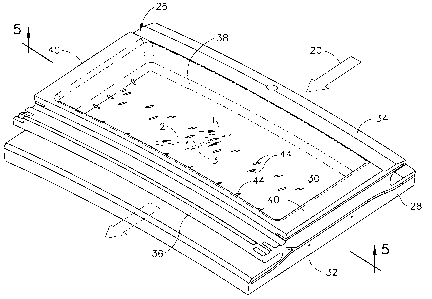
Figure 2 is an isometric view of the top or backside of an exemplary portion
of the first
stage turbine shroud illustrated in Figure 1.
Figure 3 is a planiform view of an arcuate portion of the turbine shroud
illustrated in
Figure 2 disposed in the collective annular shroud illustrated in Figure 1 and
taken
generally along line 3-3.
Figure 4 is an elevational sectional view through the turbine shroud
illustrated in Figure
3 and taken along inclined line 4-4 in position above the tip of the first
stage turbine
rotor blade.
Figure 5 is a bottom or underside view of the turbine shroud illustrated in
Figure 2 and
taken along line 5-5.
Figure 6 is an axial sectional view, like Figure 4, of the turbine shroud
illustrated in
Figure 5 and taken along jog line 6-6.
Figure 7 is a plan view of a portion of the front side of the turbine shroud
illustrated in
Figure 5, along with a flowchart method for distributing the film cooling
holes therein.
- 5 -
CA 02551218 2006-06-29
167257 (13DV)
DETAILED DESCRIPTION OF THE INVENTION
Illustrated schematically in Figure 1 is a portion of a gas turbine engine 10
configured
for powering an aircraft in flight in a typical application. The engine is
axisymmetrical
around an axial centerline axis 12 and includes a conventional, multistage
axial
compressor 14 which is effective for pressurizing air 16 during operation.
The pressurized air is mixed with fuel in an annular combustor 18, shown in
aft part, for
generating hot combustion gases 20 that are discharged from the outlet thereof
during
operation.
A first stage turbine nozzle includes a row of hollow first stage nozzle vanes
22
supported between radially outer and inner bands at the outlet end of the
combustor.
The vanes are configured for directing the combustion gases 20 obliquely into
a row of
first stage turbine rotor blades 24 disposed directly aft therefrom in the
downstream
direction in the longitudinal direction along the engine centerline axis 12.
Additional
stages of nozzle vanes and rotor blades follow the first stage rotor blades in
a
conventional configuration.
The first stage blades 24 include integral dovetails mounted in corresponding
slots in the
perimeter of a supporting rotor disk, which disk in turn is joined to the
rotor of the
compressor 14 for powering the several rows of compressor blades therein.
The rows of vanes 22 and blades 24 define the first stage of the HPT, which
may include
a second stage, and is followed typically by several stages of the LPT that
extract further
energy from the combustion gases. The rotor of the LPT is typically joined to
a fan (not
shown) in a typical aircraft engine application, or may be joined to an
external drive
shaft (not shown) for typical marine and industrial applications.
As indicated above in the Background section, the combustion gases 20 are
quite hot
during operation and correspondingly provide high heat loads to the various
metal
components over which the combustion gases flow during operation. Accordingly,
the
various turbine components exposed to the combustion gases are typically
cooled by
- 6 -
CA 02551218 2011-05-26
167257 (13DV)
bleeding a portion of the pressurized air 16 from the compressor, which air,
therefore,
bypasses the combustor and reduces overall efficiency of the engine.
The liners of the combustor 18, the nozzle vanes 22 and their supporting
bands, and the
turbine blades 24 are some examples of typical turbine components which may be
cooled by the pressurized air 16 using conventional film cooling holes, among
other
types of cooling features.
In particular, however, a specific form of turbine component which may enjoy
improved
film cooling as disclosed hereinbelow is the first stage turbine shroud 26.
The turbine
shroud is illustrated in axial section in Figure 1 and comprises an annular
outer boundary
for the combustion gases 20 that flow downstream between the first stage
turbine blades
24.
The turbine shroud 26 is typically formed in a row of arcuate segments one of
which is
illustrated in isolation in Figure 2 that adjoin each other circumferentially
as illustrated in
part in Figure 3, with conventional spline seals (not shown) being mounted in
corresponding slots in the split-line joints between the shroud segments.
Figure 4
illustrates a typical axial cross section through the turbine shroud 26
positioned closely
adjacent to the radially outer tip of the first stage turbine rotor blades 24.
As initially shown in Figure 2, each segment of the turbine shroud 26 includes
an arcuate
plate or wall 28 having a suitable radius from the centerline axis of the
engine. The
shroud wall 28 includes a radially outer back surface or side 30, and an
opposite, radially
inner front surface or side 32, with a suitable thickness therebetween.
An axially forward rail or hook 34 extends from the back side 30 immediately
aft of the
leading edge thereof, and an axially aft rail or hook 36 is disposed at the
longitudinally or
axially opposite end of the wall spaced forwardly of the trailing edge
thereof.
A central pocket 38 is bounded axially forward and aft by the opposite hooks
34,36, and
is additionally bounded circumferentially or laterally by integral side rails
40. The
opposite side rails include end slots in which conventional spline seals (not
shown) are
- 7 -
CA 02551218 2006-06-29
167257 (13DV)
mounted for sealing the joint between circumferentially adjoining segments of
the
collective turbine shroud when assembled in the engine around the full row of
turbine
rotor blades as illustrated in Figure 1. The turbine shroud 26 is mounted by
its forward
and aft hooks 34,36 to a surrounding hanger 42, which in turn is suspended
from an
annular casing of the engine.
The basic configuration of the turbine shroud 26 as illustrated in Figures 1
and 2 is
conventional and defines the outer flowpath or boundary for the hot combustion
gases as
they flow axially downstream between the first stage turbine rotor blades 24.
The
turbine shroud 26 may be formed of a conventional superalloy metal having
enhanced
strength at the elevated temperatures experienced in the hostile environment
of the HPT.
The turbine shroud 26 is modified as described hereinbelow for providing
enhanced
cooling thereof during operation.
As initially shown in Figures 3 and 4, the shroud wall 28 includes a plurality
or
multitude of film cooling holes 1,2,3,4,5 arranged in multiple rows extending
circumferentially or laterally over the width of the turbine shroud. As shown
in
sectional view in Figure 4, each of the film cooling holes is inclined
longitudinally
through the wall 28 at an inclination or slope angle A.
The slope angle is preferably shallow in the optimum range of about 15 degrees
to about
20 degrees where possible for discharging cooling air 16 in a thin film along
the front
side 32 of the wall for creating a thermally insulating air film therealong in
the
downstream direction. The cooling air 16 is a portion of the pressurized air
bled from
the compressor 14 and is suitably channeled through the hanger 42 as
illustrated in
Figure 1, and is initially received in the pocket 38 on the back side of the
turbine shroud.
As initially shown in Figures 4 and 6, each of the five rows of film cooling
holes 1-5
includes a corresponding inlet 44 disposed on the back side 30 of the wall
inside the
pocket 38. Each of the five rows also includes a corresponding outlet 46
disposed on the
front side 32 of the wall. The individual holes themselves are conventional
and may be
cylindrical and suitably formed by laser drilling in conventional practice.
- 8 -
CA 02551218 2006-06-29
167257 (13DV)
Since the film cooling holes are inclined at the shallow slope angle, the
respective inlets
44 and outlets 46 will form oval or elliptical perimeters on the opposite
sides 30,32 of
the wall. Each film cooling hole 1-5 is therefore a discrete and independent
hole that
receives the cooling air 16 from the pocket 38 and discharges that air in a
corresponding
jet at a shallow discharge angle along the front side 32 of the wall which is
directly
exposed to the hot combustion gases flowing between the turbine blades.
The various outlets 46 of the film cooling holes are illustrated in Figure 5
in five rows
extending circumferentially or laterally across the width of the turbine
shroud, with the
outlets and rows being suitably spaced apart axially along the downstream flow
direction
of the combustion gases 20 at a longitudinal pitch or spacing B, which varies
from row
to row as desired for maximizing the cooling effectiveness of the pattern of
outlet holes.
And, the outlets 46 in each of the five rows have a circumferential or lateral
pitch or
spacing C also selected for maximizing cooling effectiveness.
As indicated above in the Background section, film cooling holes are quite
conventional
and are found in various configurations, various orientations, and various
patterns
typically tailored for the specific turbine engine component that requires
film cooling
against the heat loads from the hot combustion gases.
However, conventional film cooling holes are typically arranged in uniform
rows, with
adjacent rows thereof having similarly inclined film cooling holes disposed in
a
unidirectional pattern. The adjacent rows may therefore be packed closely
together in
high density where required without the film cooling holes intersecting each
other or
being too closely packed together which would reduce the mechanical strength
of the
metal substrate itself.
In the example of the turbine shroud illustrated in Figure 2, the forward and
aft hooks
34,36, and the side rails 40 occupy a substantial portion of the surface area
of the back
side 30 and limit the ability to introduce suitable film cooling holes through
the wall
thereof. The perimeter of the pocket 38 limits the location of the film
cooling holes by
placing the inlets therein, and typically requires inclination angles of the
film cooling
- 9 -
CA 02551218 2006-06-29
167257 (13DV)
holes to significantly exceed the optimum shallow range of 15-20 degrees for
the
placement thereof.
Inclination angles approaching perpendicular to the turbine wall may be
required of the
film cooling holes located near the boundary of the central pocket 38 for
effectively
discharging cooling air near the perimeter of the front side 32. Such oblique
film
cooling holes effect reduced efficiency, and correspondingly require more of
such
oblique holes, and the use of more cooling air bled from the compressor for
achieving
the desired long useful life of the turbine shroud.
As shown in Figures 4 and 5, the film cooling holes 1-5 in the five rows are
spaced apart
laterally at a suitable lateral spacing C in each row, with the holes from row
to row being
suitably laterally spaced apart or offset from each other to stagger the rows
along the
lateral direction. Correspondingly, longitudinally adjacent rows may then be
inclined in
opposite aft and forward directions respectively for channeling the cooling
air 16
therethrough in counterflow.
For example, in a method of distributing a multitude of film cooling holes 1-5
through
the wall 28 illustrated in Figures 4 and 7, multiple rows thereof such as the
aft three
rows of film cooling holes 3,4,5 are distributed longitudinally and laterally
through the
wall and inclined longitudinally therethrough in a first or aft direction for
effecting a
corresponding pattern of the outlets 46 thereof on the front side 32 of the
wall for in turn
effecting film cooling of the front side by the collective discharge of
corresponding air
jets from the individual holes.
Correspondingly, additional rows such as the two forward rows of film cooling
holes 1,2
may be distributed longitudinally and laterally through the wall 28 and
inclined
longitudinally therethrough in a second or forward direction opposite to the
first
direction of the aft rows. The forward inclined holes 1,2 are offset or
staggered laterally
from the aft inclined holes 3,4,5 as best illustrated in Figure 5.
In Figure 5, the outlets 46 are shown in solid line on the exposed front side
32 of the
shroud. The corresponding inlets 44 of the five rows of film cooling holes are
shown in
-10-
CA 02551218 2006-06-29
167257 (13DV)
dashed line on the opposite, hidden back side 30 of the shroud. And, the
longitudinal
centerline axes of the individual film cooling holes are shown in phantom
line, with
arrows indicating the corresponding forward and aft directions of the film
cooling air
discharged therethrough.
Counterflow of film cooling air may be locally effected where desired in
adjacent pairs
of film cooling holes preferably in adjacent rows or pair of rows which may
use the
lateral offset or stagger between holes to advantage.
As shown in Figures 3 and 4, all of the inlets 44 of the five rows of holes 1-
5 are spaced
apart laterally and longitudinally inside the common pocket 38 on the back
side 30 of the
wall 28. Each of the film cooling holes 1-5 has a single outlet 46
corresponding to the
single inlet 44, with the outlets 46 also being spaced apart laterally and
longitudinally on
the opposite front side 32 of the wall 28 in correspondingly different two
dimensional
(2D) patterns for discharging discrete jets from each of the multitude of film
cooling
holes.
As shown in Figure 4, the film cooling holes in longitudinally adjacent rows
are inclined
oppositely between respective inlets 44 and outlets 46 to channel the cooling
air 16 in
longitudinal counterflow in discrete jets of air spaced laterally apart. In
this counterflow
configuration, laterally adjacent film cooling holes longitudinally overcross
or overlap
each other, at least in part, without intersecting each other.
For example, Figures 4 and 5 illustrate that the first row of holes 1 is
inclined forwardly
in counterflow with the third row of holes 3 which is inclined in the aft
direction. The
third row of holes 3 is also disposed in counterflow with the second row of
holes 2
which is also inclined in the forward direction like the first row.
And, the second row of holes 2 is also disposed in counterflow with the fourth
row of
holes 4 in the Figure 6 species, but not in the Figure 4 species. The fifth
row of holes 5
provides additional film cooling in parallel with the fourth row of holes 4,
both rows
being inclined in the aft direction.
- 11 -
CA 02551218 2006-06-29
167257 (13DV)
The advantage of the counterflow combination of longitudinally and laterally
adjacent
film cooling holes may be appreciated in Figure 4. If the first two rows of
holes 1,2
were not in counterflow with the third and fourth rows, they would have to be
longitudinally or axially spaced apart therefrom more closely to the forward
hook where
space permits, or alternatively, their direction of inclination would have to
be reversed to
match in parallel the aft direction of inclination of the aft three rows, yet
again, where
space permits near the forward hook.
However, the forward hook presents a substantial obstacle for the introduction
of
conventional film cooling holes. The desired location of the hole outlets is
determined
by the specific heat load from the combustion gases, which in turn determines
the
location of the corresponding inlets inclined therefrom.
The film cooling holes must be distributed both axially and circumferentially
for
matching the heat loads and for maintaining structural integrity of the
turbine wall itself.
The optimum shallow inclination angle of conventional film cooling holes may
then
cause their inlets to interfere with the forward hook in this example.
By inclining the forward holes in Figure 4 oppositely to the aft holes the
limited surface
area in the pocket 38 may be used to advantage for distributing the limited
cooling air
over the front wall 32, while maintaining in most cases the shallow
inclination angles of
most, if not all, of the film cooling holes distributed throughout the pocket
38.
The new configuration of the oppositely inclined rows of film cooling holes
illustrated
in Figures 4 and 6 permits counterflow in opposite directions between any
adjacent pair
of film cooling holes in closely adjacent rows thereof. For example, the film
cooling
holes 1-4 in the first four rows may be oppositely inclined longitudinally in
pairs so that
the inclined holes converge in longitudinal direction from the back side 30
initially
toward the opposite front side 32. In this example, the first and third holes
1,3 initially
converge together as they extend downwardly from the back side 30.
Adjacent film cooling holes may also be oppositely inclined to diverge apart
in
longitudinal direction toward the front side 32. In Figure 4, the first and
third holes 1,3
- 12 -
CA 02551218 2006-06-29
167257 (13DV)
diverge in this fashion, as well as the second and third holes 2,3 and the
second and
fourth holes 2,4.
In the exemplary embodiment illustrated in Figure 4, adjacent film cooling
holes may
both converge together from the back side 30 and diverge apart toward the
front side 32,
while increasing the extent of overcrossing or crossing in the longitudinal
direction
without intersecting. This overcrossing of counterflow film cooling holes is
represented
by the first and third holes 1,3 which cross near the back side 30, as well as
by the
second and third holes 2,3 which cross near the middle of the wall thickness.
Depending upon the longitudinal position of the adjacent film cooling holes,
the amount
of crossing can be varied from little to great between the corresponding
inlets and outlets
thereof. For example, the corresponding inlets 44 may be laterally aligned
with
minimum longitudinal overcross or overlap (not shown). Or, the inlets may be
longitudinally offset from each other with different extent as shown in Figure
6 for hole
pairs 1,3; 2,3; and 2,4. Correspondingly, the respective outlets 46 of the
counterflow
film cooling holes may be offset forward and aft from the inlets thereof as
shown in
Figures 4 and 6, or could be laterally aligned with minimum overcross or
overlap in
another embodiment not shown.
Figure 5 illustrates the predominant oblique inclination of the combustion
gases 20 as
they are discharged from the nozzle vanes toward the first stage turbine
blades. The film
cooling holes 1-5 are preferably skewed relative to the axial axis or
centerline axis of the
shroud at an inclination or skew angle D in the lateral or circumferential
direction. In
this way, the inlets 44 of the individual film cooling holes are laterally
offset or
staggered from their respective outlets 46 in a similar fashion in each of the
five rows,
and preferably with the skew angle varying as required between the several
rows.
The exemplary film cooling holes 1-5 illustrated in Figure 5 are cylindrical
in section
along their longitudinal or centerline axes, and result in the oval outlets 46
illustrated in
Figure 5 having major axes disposed substantially normal to the incidence
angle of the
combustion gases 20 for spreading the discharged film cooling air relative
thereto.
- 13 -
CA 02551218 2006-06-29
167257 (13DV)
The oblique skew angle D illustrated in Figure 5 also permits the longitudinal
length L
of the individual film cooling holes to be increased where practical when
achieving the
shallow slope angle A, as well as for effecting the various counterflow and
overcrossing
species of the adjacent film cooling holes without intersection thereof while
maintaining
suitable spacing therebetween.
Since the counterflow cooling holes have shallow inclination angles, they are
effective
for providing enhanced film cooling from the corresponding outlets thereof.
Furthermore, in the various overcrossing species of the counterflow holes,
additional
internal convection cooling of the wall itself may be obtained in the
immediate region of
the overcrossing holes.
In the exemplary embodiment illustrated in Figure 5, the several outlets 46 of
the several
rows of film cooling holes 1-5 are collectively distributed longitudinally and
laterally
with corresponding pitch or spacing B,C therebetween in a 2D outlet pattern
for the
entire front side 32 of the wall. This outlet pattern includes a high density
grouping or
region identified by the outlets for the aft three rows of holes 3-5, and a
relatively low
density grouping or region identified by the outlets for the forward two rows
of the film
cooling holes 1,2.
The high density region of the outlets 46 as illustrated in Figure 4
corresponds with the
aft end of the turbine blades 24 wherein the shroud aft end is subject to
relatively high
heat loads from the combustion gases. The high density region therefore
provides
locally enhanced film cooling for the shroud aft end.
Correspondingly, the low density region of holes 1,2 is disposed upstream near
the
forward ends of the turbine blades, and the shroud forward end requires less
cooling for
the relatively low heat loads in this region.
As shown in Figures 4 and 5, the high and low density regions are bridged by
the film
cooling holes in longitudinally adjacent rows by the longitudinally opposite
inclination
thereof in counterflow. For example, holes 2 overcross holes 1 and 3 in
counterflow
therewith. And, holes 1 overcross holes 3 in further counterflow. These first
three rows
- 14 -
CA 02551218 2006-06-29
167257 (13DV)
of overcrossing holes 1-3 are thereby packed closely together side by side in
the limited
area of the pocket 38 and may all enjoy the optimum, shallow inclination angle
thereof
down to about 15 degrees.
In the species illustrated in Figures 4 and 5, the high density region of
outlets 46 is
disposed longitudinally aft or downstream from the low density region of the
outlets 46.
This configuration provides enhanced performance for military aircraft engines
in
particular.
Alternatively, the high density region of the outlets may be disposed
longitudinally
forward of the low density region corresponding respectively with the forward
and aft
ends of the turbine rotor blades. This configuration (not shown) can provide
enhanced
performance for commercial aircraft engines.
As shown in Figures 3 and 4, the several inlets 44 of the several rows of film
cooling
holes 1-5 are collectively distributed longitudinally and laterally in an
inlet pattern over
the back side 30 of the wall inside the pocket 38 in a smaller surface area
than the
pattern of outlets 46 illustrated in Figure 5. The entire front side 32 of the
turbine
shroud is exposed to the hot combustion gases during operation. However, the
forward
and aft hooks and side rails bound the pocket 38 and limit the available area
of the
pocket for receiving the cooling air to correspondingly less than the front
side area.
The pattern of outlets 46 may be distributed over a larger surface area on the
shroud
front side for providing effective cooling thereof, with the corresponding
film cooling
holes being commonly fed from the central supply pocket 38 in which the
corresponding
inlets 44 are disposed over a smaller surface area.
The ability to include oppositely inclined, counterflow film cooling holes
within the full
pattern of holes permits additional tailoring of that pattern within the
limited area
provided by the pocket 38 for maintaining the inclination angles of most, if
not all, of
the film cooling holes at or near the optimum value thereof.
In the exemplary embodiment illustrated in Figure 4, the pattern of outlets 46
includes
three rows of film cooling holes 3,4,5 inclined longitudinally aft between the
back and
- 15 -
CA 02551218 2006-06-29
167257 (13DV)
front sides 30,32, with the corresponding inlets thereof being disposed
forward of the
outlets. In this way, the holes 3-5 incline aft to position the outlets
thereof in the desired
region of high heat load, with the last two rows of holes 4,5 extending under
the aft hook
36.
Correspondingly, two rows of film cooling holes 1,2 are inclined longitudinal
forward in
this embodiment between the back and front sides of the wall, with the
corresponding
inlets being disposed aft of the outlets. These forwardly inclined holes
position the
outlets in the low heat load region and initiate film cooling of the front
side which film
cooling continues aft and is re-energized by the aft inclined film cooling
holes.
As indicated above with respect to Figure 5, the combustion gases 20 flow
obliquely in
the downstream direction as they pass below the turbine shroud. The several
rows of
film cooling holes are therefore skewed from the longitudinal or axial
direction to
provide oval outlets whose major axes are oblique or perpendicular to the flow
streamlines for improving the film cooling effect.
The various rows of forward and aft inclined holes 1-4 overcross each other at
least in
part longitudinally, and vary in skew angle D laterally to prevent
intersection between
the discrete film cooling holes and avoid flow communication therebetween.
Figure 5
illustrates the various skew angles D of the longitudinal directions of the
corresponding
film cooling holes in the five exemplary rows thereof. The high density
outlets 46 in the
aft three rows of holes 3-5 have a relatively close pitch spacing B,C both
longitudinally
and laterally. These hole also have a relatively large skew angle D.
Correspondingly, the low density outlets 46 of the forward two rows of holes
1,2 have a
larger pitch spacing B,C both longitudinally and laterally, with
correspondingly smaller
skew angles D.
Figure 7 reproduces a portion of the exemplary turbine shroud illustrated in
Figure 5
which includes the low density outlets 46 of the forward two rows of holes
1,2, and the
high density outlets 46 of the aft three rows of holes 3,4,5. Figure 7 also
includes a
flowchart summarizing the preferred method for distributing the plurality of
film cooling
- 16 -
CA 02551218 2006-06-29
167257 (13DV)
holes 1-5 through the wall 28 of the turbine shroud for maximizing
effectiveness of
those limited number of holes in the counterflow configuration thereof.
The high density rows of film cooling holes 3,4,5 are preferably introduced
first in the
desired location of the turbine shroud, such as the aft portion thereof. Then,
the
additional forward rows of low density film cooling holes 1,2 are distributed
through the
forward portion of the turbine shroud in counterflow with the high density
holes. The
high density holes are inclined through the wall in a first or aft direction,
and the low
density holes are inclined through the wall in an opposite or forward second
direction.
Counterflow is effected by laterally offsetting or staggering the forward and
aft inclined
holes from each other to prevent intersection thereof while ensuring that the
oppositely
inclined holes overcross at least in part. Some or all of the film cooling
holes in the
longitudinally adjacent rows of the oppositely inclined holes may overlap or
overcross
longitudinally in various amounts for effecting the desired optimum shallow
inclination
thereof within the limited surface area provided by the air supply pocket 38.
The high density holes 3-5 are first introduced at correspondingly shallow
slope angles
A as illustrated in Figure 6, for example, to effect a substantially uniform
pattern of the
outlets 46 in the front side 32 of the shroud as illustrated in Figure 5. The
low density
holes 1,2 may then be distributed through the wall at correspondingly shallow
slope
angles A to complement the high density holes.
The skew angle D of the low density holes 1,2 may then be varied as required
to prevent
intersection of the low density holes with the oppositely inclined high
density holes.
Since the longitudinal and lateral spacing B,C of the high density holes 3-5
is preferably
uniform, the longitudinal and lateral spacing B,C of the low density holes 1,2
may be
varied in conjunction with varying the skew angle D thereof for preventing
intersection
between the oppositely inclined counterflow holes.
Furthermore, the length L of the various film cooling holes may also be varied
to assist
in preventing intersection of the counterflow holes.
- 17-
CA 02551218 2006-06-29
167257 (13DV)
Figure 5 illustrates the complete pattern of the five rows of film cooling
holes 1-5 in an
exemplary embodiment in which longitudinal and lateral spacing B,C and skew
angle D
and length L of the various holes have been selected for introducing the
counterflow
film cooling holes in a preferred pattern specifically tailored for greater
heat loads at the
aft end of the shroud.
Figure 4 illustrates a representative cross section of the shroud in which the
first holes 1
are disposed in crossflow with the third holes 3 near their inlets. The second
holes 2 are
also disposed in crossflow with the third holes 3 near their middle. And, the
second and
fourth holes 2,4 are disposed in counterflow, but not in crossflow since they
are
longitudinally spaced apart from each other in whole.
However, Figure 6 illustrates another section of the turbine shroud near one
of the side
rails as illustrated in Figure 5 which generally matches the cross section of
Figure 4,
except that one of the fourth holes 4 overcrosses in crossflow one of the
second holes 2.
Since the various rows of film cooling holes illustrated in Figure 5 have
corresponding
skew angles D which are oblique to the longitudinal or axial axis of the
shroud, local
tailoring of the film cooling holes is required near the side rails, and near
the aft hook in
particular. The row of fourth holes 4 illustrated in Figure 5 is generally
uniform, but in
view of the large skew angle D thereof insufficient space exists at the left
side of the
shroud for introducing the left-most hole 4 in substantially the same
orientation as the
remainder of holes 4.
Accordingly, the local position of the left-most hole 4 is varied from the
remainder of
fourth holes 4 so that the outlet 46 thereof is aligned with the remainder of
outlets in the
fourth row, with the inlet of this left-most fourth hole 4 being suitably
located to prevent
interference with the side rail and the other film cooling holes in the
shroud.
Since the film cooling holes 1-5 should be inclined at the optimum shallow
inclination
angle of about 15 degrees, the inclination angle thereof may be varied lastly
as required
to prevent intersection between adjacent film cooling holes. Increasing the
inclination
angle A of the film cooling holes may be required near the opposite side rails
illustrated
- 18-
CA 02551218 2006-06-29
167257 (13DV)
in Figures 2 and 5, and near the forward and aft hooks where these components
interfere
with the optimum placement of the film cooling holes.
As indicated above, the use of typical film cooling holes in turbine shrouds
is
conventional, and the patterns thereof must be modified as required near the
forward and
aft hooks and side rails in view of the obstructions therefrom. Each design
requires
tailoring for the specific heat loads experienced by the shroud and for the
specific
geometry thereof.
Various forms and configurations of film cooling holes may be used in the
turbine
shroud disclosed above in otherwise conventional practice. However, the
ability to
introduce counterflow film cooling holes and their overcrossing or crossflow
advantages
as described above permits additional tailoring of the cooling performance of
turbine
shrouds.
The turbine shroud disclosed above may be otherwise conventional in
configuration, yet
modified for the introduction of the counterflow film cooling holes as
required for the
specific engine application. The exemplary turbine shroud disclosed above may
be used
as a retrofit for the previous imperforate turbine shroud protected solely by
the TBC.
Instead, the turbine shroud disclosed above is devoid of any TBC, and relies
on the
special pattern of film cooling holes including the counterflow holes therein
for
achieving the desired long life of the shroud in operation, at the efficiency
cost of
providing the film cooling air therethrough.
The introduction of the counterflow film cooling holes is not limited to the
turbine
shroud component disclosed above. For example, the flowchart in Figure 7
illustrates
schematically that the counterflow film cooling holes may also be used in any
turbine
component or part 48 in a gas turbine engine which is otherwise cooled by
unidirectional
film cooling holes. Where the geometry in the miscellaneous turbine part
prevents
introduction of optimally inclined film cooling holes, the counterflow holes
disclosed
above may be introduced where practical.
Examples of such additional turbine parts have been disclosed above, and
include the
- 19 -
CA 02551218 2013-09-19
167257 (13DV)
airfoils of the turbine vanes and blades, and the combustor liner itself
The introduction of the counterflow film cooling holes in the various turbine
components
allows more film cooling holes to be drilled at the optimum shallow breakout
angles of
about 15 degrees and thereby reduces the number of conventional holes having
larger
breakout angles due to geometrical constraints. The optimum inclination angles
correspondingly increase the film coverage from each hole which in turn
reduces the
need for additional non-optimized film holes with larger inclination angles
which would
require more chargeable cooling flow from the compressor.
The various film cooling holes disclosed above are shown in their simple
cylindrical
configuration with relatively constant flow area between the inlets and
outlets thereof. In
alternate embodiments, other forms of film cooling holes could also be used,
such as the
more complex diffusion film cooling holes that increase in flow area between
their inlets
and outlets for diffusing the cooling air, and correspondingly reducing the
velocity
thereof.
An additional advantage of the overcrossing film cooling holes disclosed above
is the
local increase in internal convection cooling of the turbine wall itself in
the region of
crossing. Nevertheless, sufficient material exists between adjacent holes to
prevent flow
communication therebetween while also maintaining structural integrity of the
wall
without undesirably large stress therein.
While there have been described herein what are considered to be preferred and
exemplary embodiments of the present invention, other modifications of the
invention
shall be apparent to those skilled in the art from the teachings herein, and
it is, therefore,
desired to be secured in the appended claims all such modifications as fall
within the
scope of the invention described.
- 20 -