Note : Les descriptions sont présentées dans la langue officielle dans laquelle elles ont été soumises.
CA 02553606 2006-07-17
WO 2005/080743 PCT/SE2005/000111
1
Drill sting component, wear protection component and cutter head for use in a
rock drilling process.
Field of the invention
The invention relates to a drill string component for use in a
drilling process as defined in the preamble of claim 1_
The invention further relates to a wear protection component
for use with a drill string component as defined in the
preamble of claim 7. The invention also relates to a cutter
head for use with a drill string component as defined in the
preamble of claim 14.
Background of the invention
Drilling apparatuses may be used in a number of applications.
For example, rock drilling apparatuses may be used in
tunnelling, underground mining, rock reinforcement, raise
boring, and for drilling of blast holes, grout holes and holes
for installing rock bolts.
Common for drilling processes is that the drill cuttirigs have
to be moved from the cutting face during the drilling process.
Depending on drilling method, this may be accomplished in a
number of ways. For example, one common method is to f lush the
drill cuttings away from the hole with a suitable medi um. The
drill cuttings may fox example be flushed out of the hole by a
flushing medium that is fed through a tube in, preferably the
center of, a drill string connecting a drill tool to a drill
rig, and discharged near the drill tool in order to also cool
the drill tool. The flushing medium then flushes the drill
cuttings through and out of the hole.
Another method for removing drill cuttings is to evacuate the
drill cuttings through the drill string, for example by
supplying the cooling and/or flushing medium to the cutting
CA 02553606 2006-07-17
WO 2005/080743 PCT/SE2005/000111
2
area in the space between the drill string and rock wall so
that the drill cuttings then are flushed through a channel in
the drill string.
This flushing medium is usually air in surface drilling
apparatuses and water in underground working apparatuses.
Alternatively, watermist with or without a chemical additive
or foam may be used in both types of apparatuses.
A problem that is encountered during rock drilling is that the
drill string, and in particular expensive drill string
components, have to be replaced.
Summary of the invention
It is an object of the present invention to provide a drill
string component for use in a drilling process that solves the
above mentioned problem.
This object is achieved by a drill string component according
to the characterizing portion of claim 1.
It is a further object of the present invention to provide a
wear protection component that solves the above mention ed
problem.
This object is achieved by a wear protection component
according to the characterizing portion of claim 7.
It is also an object of the present invention to provide a
cutter head that solves the above mentioned problem.
This object is achieved by a cutter head according to t he
characterizing portion of claim 14.
CA 02553606 2006-07-17
WO 2005/080743 PCT/SE2005/000111
3
The drill string component according to the present invention
comprises an outer casing and a channel for evacuating drill
cuttings from a rock cutting surface. The channel is
constituted by a first tubular member, and at least one
portion of the first tubular member, which in operation is
subjected to wear from drill cuttings, is, or is provided
with, a replaceable wear protection component. This has the
advantage that drill string components may be repaired at a
considerably lower cost than would be the cost of replacing
them with new ones. It further has the advantage that the
drill string component can be produced by a less costly
material since requirements regarding wear resistance can be
relieved.
The first tubular member may be a replaceable tubular wear
protection component. This has the advantage that the channel
for evacuating drill cuttings may be replaced in a simple
manner when the existing channel has been subject to extensive
wear.
The first tubular member may be arranged to receive a second
tubular member constituting the replaceable wear component.
This has the advantage that an even cheaper component may be
used since it does not have to be able to withstand
transversal forces due to the support by the outer casing.
The drill string component may be provided with an annular
projection arranged to abut a wear protection component. This
has the advantage that the wear protection component may be
kept in position in a simple manner.
The drill string component may be arranged such that a wear
protection component can be attached to it by a screw joint
reinforcement. This has the advantage that it provides an
CA 02553606 2006-07-17
WO 2005/080743 PCT/SE2005/000111
4
alternative way to keep the wear protection component in
position in a simple manner.
A wear protection component according to the present invention
includes a first surface, which is an area of wear, and means
for engagement with corresponding means of the drill string
component, such that when it is engaged, the first surface
forms at least part of said channel.
The first and/or second tubular member may be made from a
material from the group: plastic such as PVC, metal or a
ceramic material.
Brief description of the drawings
Fig. 1 is a section through a drift extending through a rock
and a rock drilling apparatus therein for drilling a series of
intersecting holes.
Fig. 2 shows a front view of the rock drilling of fig. 1.
Fig. 3 shows in a longitudinal section a cutter head and a
drill string component according to the present invention.
Fig. 4 shows in a longitudinal section a drill string
component according to the present invention.
Fig. 5a-5e show alternative embodiments of a drill string
component and wear protection component according to the
present invention.
Detailed description of exemplary embodiments
In fig. 1 and 2 is shown a rock drilling apparatus 1 suitable
for use with the present invention. In Fig. 1 the rock
drilling apparatus 1 is shown having at its left end a
compartment for storing drill string components 2' to be
CA 02553606 2006-07-17
WO 2005/080743 PCT/SE2005/000111
assembled into a drill string. A derrick 8 includes assembling
means for assembling the drill string components into a drill
string getting longer and longer as the drilling process goes
on. The assembling means may be constituted by a holding
5 wrench.
In fig. 2 is shown a front view of the rock drilling apparatus
in an ongoing drilling process. As is shown, the apparatus 1
is used to excavate an inclined cylindrical portion of a rook
formation.
The drilling is performed by a reamer 3 with a relatively
larger diameter. The reamer 3 is mounted together with a pilot
bit 4 of a smaller diameter. The pilot bit is used to
ascertain that the drilling is performed in a desired
direction throughout the drilling of the particular hole. The
reamer 3 is carried by a drill string 2, at present
constituted by drill string components 2a, fib, 2c, where
additional drill string components 2d, 2e, etc. (not shown)
may be added to the drill string by the assembling device as
the drilling process progresses until a hole of desired length
has been acquired. Each drill string component 2' may for
example be of 1000 mm length.
The yielded drill cuttings must continuously be removed and in
the particular apparatus shown, drill cuttings are evacuated
through a channel in the drill string. When drilling
substantially vertically upwards the drill cuttings may be
evacuated through the channel by the attraction of gravity.
The evacuation may, however, advantageously be assisted by for
example either: i) providing a flushing medium to the drilling
area which then flushes the drill cuttings through the channel
in the drill string and out of the hole, the flushing medium
for example being supplied to the drilling area through a
CA 02553606 2006-07-17
WO 2005/080743 PCT/SE2005/000111
6
second channel in the drill string or in the space between
drill string and rock wall, or ii) connectring the drill string
to a suction device 5 via a hose 6 (shown in fig. 1), so that
the suction device 5 then sucks all drill cuttings from both
pilot drill and reamer via the channel in the drill string.
The evacuation of drill cuttings through a channel in the
drill string, however, has the disadvantage that the drill
string components are subject to substantive wear caused by
the drill cuttings, in particular when the evacuation is
forced by flushing and/or suction. When t1-ze drill string
component has been subjected to such severe wear that it has
to be replaced, this is associated with a substantial cost.
This is for example due to the cost of high-strength steel
that is used to produce the drill string component and to
complex threads that has to be used to secure drill string
components to each other in order for the drill string to be
capable of handling the forces and torsion it is subjected to
during a drilling process.
In fig. 3 is shown a drill string component 30 according to
the present invention, at one end connected to a reamer 31,
and at its other end being intended to be connected to another
drill string component or, if the drillin g process is in its
beginning, the rock drill device. The actual rock breaking
action is performed by continuously apply ~.ng pressure onto the
drill string so that the pilot bit cutter s 32, and the reamer
cutters 33, 34 are continuously pressed against the rock,
while simultaneously the drill string is rotated. In this
example, the pilot bit cutters are constituted by three
sonically shaped roller bits with tungste n carbide inserts and
each with an axis inclined at an angle relative to the normal
to the axis of the drill string in such a manner that the
pilot bit cutters are normal to the drill string when facing
CA 02553606 2006-07-17
WO 2005/080743 PCT/SE2005/000111
7
the rock. The diameter of the roller bits may for example be
9-14 inches. The cutters 33, 34 cause annular kerfs, and when
the kerfs are deep enough the rock between the kerfs falls
off. The cutters 45 are provided to make sure that the reamer
may be pulled out of the hole backwards towards the machine
without getting stuck when the drilling of the hole is
finished and the machine is to be moved to another hole. The
reamer diameter may for example be 500-2000 mm. The distance
between the pilot bit cutters 32 and the reamer cutters may
for example be 500-1000 mm.
When the drilling process is in progress, drill cuttings of
the pilot bit along with the drill cuttings produced by the
reamer are led to a center channel 37 in the drill string via
inlets 35 between the reamer cutters along the dashed arrowed
line 36. The inlets 35 may preferably be covered by wire
netting or grating to prevent large pieces from getting stuck
in the inlets.
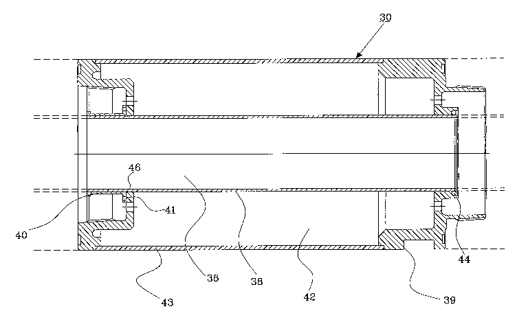
The drill string component 30 is shown in more detail in fig.
4.
In order to prevent wear of the drill string component 30, the
center channel 37 is constituted by a tubular member 38, which
is a replaceable wear protection component. In this way, only
the wear protection component 38 is exposed to passing drill
cuttings and thus the replaceable wear protection component,
and not the actual drill string component, will be subjected
to wear from passing drill cuttings. In position, the wear
protection component will protect the drill string, and in
particular the individual drill string component from wear,
and after a suitable time, when the wear protection component
is worn out, it is replaced by a similar wear protection
component. In this way, the lifetime of the drill string
CA 02553606 2006-07-17
WO 2005/080743 PCT/SE2005/000111
8
component will be extended substantially and a repair of a
drill string component by replacement of a wear protection
component may be carried out at a considerably lower cost than
would be the cost of replacing the entire drill string
component.
The wear protection component 38 is in this embodiment
inserted into the drill string component 30 from the leftmost
end thereof and is kept in position by a sleeve portion 40 as
follows. The drill string component 30 and the sleeve portion
40 each comprise a chamfered end, which together with a groove
in the wear protection component forms an annular channel 46.
A steel wire with a diameter substantially corresponding to
the diameter of the annular channel 46 is positioned inside
the annular channel 46, whereupon the wear protection
component 38 is locked in position by securing the sleeve
portion 40 to the drill string component by e.g. a number of
fasteners such as screws, indicated at 41.
The wear protection component 38 and sleeve portion 40 may be
constituted by for example a metal tube, a PVC tube, a tube
made of other plastic or a tube made of a ceramic material.
The wear protection component 38 and sleeve portion 40 may
constitute an integral part or two separate parts. Apart from
the above described example, the separate parts may for
example be welded together, threaded together, soldered
together, glued together or joined with a combination thereof.
In the figure is also shown a grip 39 for use by a holding
wrench when assembling drill string components to a drill
string. Further, the drill string component includes portions
for connecting drill string components to each other, a cutter
head or rock drill device. These portions are however not
CA 02553606 2006-07-17
WO 2005/080743 PCT/SE2005/000111
9
described in detail since this assembly is not part of the
present invention.
In this embodiment, the wear protection component 38 is
arranged such that there is a free space 42 between the wear
protection component and the outer casing 43. The free space
42 may for example be used as a second channel to supply the
drilling area with a cooling and/or flushing medium as
indicated by solid arrows 29 in fig. 3, in which the cooling
and/or flushing medium is let out in the pilot bit. A sealing
44 is used to prevent leakage of the cooling and/or flushing
medium into the channel for evacuating drill cuttings. The
flushing and cooling medium may for example be constituted by
air, water or watermist with or without a chemical additive or
foam depending of what is suitable for the particular
application.
Further, in this embodiment, the whole tubular member 38 is
replaceable. It is, however, also possible to have a tubular
member 38 constituting an integral part of the drill string
component and a thinner wear protection component that is
inserted into the integrated tubular member. In this way, an
even cheaper replacement component may be used. In this
alternative embodiment, the wear protection component may for
example be attached to the drill string component as above or
as will be described below in connection with fig. 5.
As can be seen by the broken lines in fig. 4, wear proteotion
components of adjacent drill string components will
substantially abut against each other so as to provide a
continuous protection against wear for the drill string
components throughout the drill string.
In figs. 5a-5e is shown alternative embodiments of the drill
string component and wear protection component. In these
CA 02553606 2006-07-17
WO 2005/080743 PCT/SE2005/000111
figures, the channel is defined by the outer casing of the
drill string component. The wear protection component 51 is in
fig. 5a inserted into the drill string 50 from one end thereof
and may be kept in place through friction and wear protection
5 components of adjacent drill strings (indicated by broken
lines).
In the embodiment shown in fig. 5b, the drill string component
60 is provided with an annular projection 61 at one end
thereof so as to prevent movement of the wear protection
10 component 62 relative to the drill string component 60. In
order to also protect the annular projection part of the drill
string component 60, the wear protection component 62 may in
one end be provided with a shoulder 63 as shown. As a
complement to the shoulder 63, the wear protection component
may be provided with a socket 64 as shown in fig. 5c to
protect the annular projection 61. The socket 64 partly covers
the wear protection component of the drill string component
next to the left so that there is a continuous protection
throughout the drill string.
In fig. 5d is shown yet another alternative embodiment of the
drill string component. In this embodiment, the drill string
component 70 is provided with an annular projection 71 more
towards the drill tool end of the drill string component, and
the wear protection component is provided with a socket 72 and
a projecting portion 73 arranged to fit into a connecting
drill string component. In this way, removal of the wear
protection component when it is to be replaced is facilitated.
The socket partly covers the wear protection component of the
drill string component next to the left.
Instead of having a wear protection component that covers
substantially all of the drill string component it is possible
CA 02553606 2006-07-17
WO 2005/080743 PCT/SE2005/000111
11
to use a wear protection component that only protect one or
more portions of it. These portions may be particularly
exposed portions. This is illustrated in fig. 5e where only
end portions of the drill string component are covered by a
wear protection component. This may be advantageous in order
to for example protect those portions of the drill string
component that is used to connect to other drill string
components. In the embodiment shown in fig. 5e, there is only
one wear protection component 81 for each drill string
l0 component 80 since each wear protection component 81 covers a
portion of both the drill string component it belongs to and
an adjacent drill string component. The wear protection
component is held in position by respective annular
projections 82 on the two drill string components it is
arranged to protect. It is, of course, possible to have a wear
protection component in each end of the drill string
component, or one or more wear protection components in
between as an alternative to, or in addition to the above
described.
Common for the embodiments shown in fig. 5a-5e is that the
wear protection component does not have to be able to
withstand transversal forces since it is supported by the
outer casing and thus can be produced by a less expensive
material.
In the above description protection of drill string components
have been described. It is however, also possible to apply the
present invention on cutter heads such as the reamer in fig.
3. The cutter head may comprise one or more channels to lead
the drill cuttings to a channel in the drill string. These
channels in the cutter head may be covered by suitably shaped
wear protection components which are inserted into the
channels and fixed to the cutter head. Accordingly, wear on
CA 02553606 2006-07-17
WO 2005/080743 PCT/SE2005/000111
12
the cutter head caused by drill cuttings may be limited and by
replacing wear protection components of the cutter head the
lifetime thereof may be substantially prolonged.
Although the present invention has been described in
connection with a particular rock drilling apparatus, it is to
be understood that the present invention is suitable for use
in connection with any rock drilling apparatus where the drill
string is used for evacuation of drill cuttings, in particular
rock drill apparatuses used for box hole/blind hole drillin g
in for example a tunnel, or rock drill apparatuses used for
drilling in hazardous or unhealthy minerals.
Further, in the above description, the drill cuttings have
been evacuated via a channel centrally located in the drill
string components. It is to be understood however, that also
other configurations may be used. For example, the drill
cuttings may be evacuated via a non-centrally located channel
or two or more channels. Each of these channels may of course
be protected by a wear protection component.
Also, the channel and wear protection component have been
described as having a circular cross section. The cross
section may however be square, elliptical or of any other
suitable geometrical shape.
It is also to be understood that also other types of bits and
cutters may be used with the invention since different kinds
of rock and different drilling processes may require different
kinds of cutters. For example, the cutter head need not have a
pilot bit.