Sélection de la langue

Search

Sommaire du brevet 2556379 

Énoncé de désistement de responsabilité concernant l'information provenant de tiers

Une partie des informations de ce site Web a été fournie par des sources externes. Le gouvernement du Canada n'assume aucune responsabilité concernant la précision, l'actualité ou la fiabilité des informations fournies par les sources externes. Les utilisateurs qui désirent employer cette information devraient consulter directement la source des informations. Le contenu fourni par les sources externes n'est pas assujetti aux exigences sur les langues officielles, la protection des renseignements personnels et l'accessibilité.

Disponibilité de l'Abrégé et des Revendications

L'apparition de différences dans le texte et l'image des Revendications et de l'Abrégé dépend du moment auquel le document est publié. Les textes des Revendications et de l'Abrégé sont affichés :

  • lorsque la demande peut être examinée par le public;
  • lorsque le brevet est émis (délivrance).
(12) Demande de brevet: (11) CA 2556379
(54) Titre français: REGENERATEUR DE GAZ D'ECHAPPEMENT POURVU D'UN CATALYSEUR
(54) Titre anglais: EXHAUST GAS REGENERATOR COMPRISING A CATALYST
Statut: Réputée abandonnée et au-delà du délai pour le rétablissement - en attente de la réponse à l’avis de communication rejetée
Données bibliographiques
(51) Classification internationale des brevets (CIB):
  • F02M 25/12 (2006.01)
(72) Inventeurs :
  • LEDERER, HARTMUT (Allemagne)
  • LOHBERG, WERNER (Allemagne)
(73) Titulaires :
  • WERNER LOHBERG
(71) Demandeurs :
  • WERNER LOHBERG (Allemagne)
(74) Agent: KIRBY EADES GALE BAKER
(74) Co-agent:
(45) Délivré:
(86) Date de dépôt PCT: 2005-01-15
(87) Mise à la disponibilité du public: 2005-07-28
Requête d'examen: 2010-01-14
Licence disponible: S.O.
Cédé au domaine public: S.O.
(25) Langue des documents déposés: Anglais

Traité de coopération en matière de brevets (PCT): Oui
(86) Numéro de la demande PCT: PCT/EP2005/000359
(87) Numéro de publication internationale PCT: EP2005000359
(85) Entrée nationale: 2006-09-20

(30) Données de priorité de la demande:
Numéro de la demande Pays / territoire Date
10 2004 002 742.0 (Allemagne) 2004-01-20

Abrégés

Abrégé français

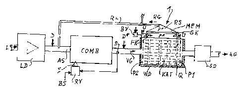
L'invention concerne un régénérateur de gaz d'échappement (VG) pourvu d'un catalyseur pour gaz d'échappement (KAT). Selon l'invention, le catalyseur (KAT) fonctionnant à chaud est adjacent à une membrane de diffusion (MEM) résistant aux températures élevées, cette membrane étant elle-même adjacente à un collecteur de gaz régénérés (RS) qui est maintenu à une pression (pr) plus basse que la pression intérieure (pk) régnant dans le catalyseur, et les gaz régénérés (RG) produits sont conduits, en tant que combustible complémentaire, à un dispositif de combustion (COMB) monté en amont du régénérateur (1) et/ou exploité autrement de façon chimico-énergétique.


Abrégé anglais


The invention relates to an exhaust gas regenerator (VG) comprising an exhaust
gas
catalyst (KAT). According to the invention, the hot-operated catalyst (KAT) is
located
adjacent to a diffusion membrane (MEM) that is resistant to high temperatures
and is,
in turn, adjacent to a regenerated gas collector (RS) that is maintained at a
lower
pressure (pr) than the respectively prevailing inner pressure (pk) in the
catalyst, and
the regenerated gas (RG) produced is supplied as a complementary fuel to a
combustion device (COMB) mounted upstream of the generator (1) and/or is used
otherwise in a chemico-energetic manner.

Revendications

Note : Les revendications sont présentées dans la langue officielle dans laquelle elles ont été soumises.


11
Claims
1. Regenerator of combustion exhaust gases (VG) with an exhaust gas catalytic
converter (KAT), characterised by the fact that the hot operated catalytic
converter
(KAT) adjoins to a high temperature resistant diffusion-membrane (MEM), which,
then again, adjoins to a reclaim collector (RS) with less internal pressure
(pr) than
the pressure (pk) in the catalytic converter, respectively, and that the thus
accumulating reclaim gas (RG) is fed into a combustion unit (COMB), upstream
of
the regenerator, as additional fuel, and/or to be used otherwise chemo-
energetically.
2. Regenerator according to claim 1, characterised by the fact that the
diffusion
membrane (MEM) consists of a high temperature-resistant microporous open-
pored ceramic.
3. Regenerator according to claim 2, characterised by the fact that the
membrane
(MEM) consists of earthy base aluminates and or silicates.
4. Regenerator according to claim 2 or 3, characterised by the fact that the
membrane (MEM) consists of aluminium oxides and/or zirconium oxides.
5. Regenerator according to one of the preceding claims, characterised by the
fact
that the membrane (MEM) is held in a fitting mounting (E) in a casing (G) that
is
welded with a frame R on one of the walls (W) of the catalytic converter (KAT)

12
6. Regenerator according to claim 5, characterised by the fact that the
membrane
(MEM) features an edge (R), tapering in the direction of the pressure gradient
(pk,
pr).
7. Regenerator according to one of the preceding claims, characterised by the
fact
that the membrane (MEM) on the side of the reclaim collector (RS) is supported
by
a perforated sheet (B).
8. Regenerator according to any one of claims 5 to 7, characterised by the
fact that at
least one electric glow plug (GK) and/or fuel-supplied flame glow plug is/are
inserted in the wall (W) or the thick-walled side (DW) or the frame (R) for
the
heating of the catalytic converter.
9. Regenerator according to any one of the preceding claims, characterised by
the
fact that the catalytic converter (KAT) is equipped upstream and downstream
with
one baffle plate (P1, P2), respectively.
10. Regenerator according to any one of the preceding claims, characterised by
the
fact that the catalytic converter (KAT) contains at least one lamellated
block,
coated with a catalyst metal, which is perforated by lateral ducts (Q) that
end near
to the membrane (MEM).
11. Regenerator according to any one of the preceding claims, characterised by
the
fact that the catalytic converter (KAT) is encased in an insulating layer (WD)

13
12 Regenerator according to any one of the preceding claims, characterised by
the
fact that the combustion unit (COMB) is supplied with air (L) and a
hydrocarbon
fuel (BS) by a control device (RV), which is connected with a lambda probe (S)
upstream to the catalytic converter (KAT).
13. Regenerator according to claim 12, characterised by the fact that water
spray or
water vapour (D, D*) is injected in controlled amounts directly into the
combustion
unit (COMB) or the catalytic converter (KAT).
14. Regenerator according to any one of the preceding claims, characterised by
the
fact that the combustion unit (COMB) is a combustion power engine.
15. Regenerator according to claim 14, characterised by the fact that an air
charging
device is connected upstream to the combustion power engine (COMB).
16. Regenerator according to claim 14 or 15, characterised by the fact that a
silencer
(SD) is connected downstream to the catalytic converter (KAT).
17. Regenerator according to claim 14 to 16, characterised by the fact that
the reclaim
gas (RG) is fed into an intake duct (AS) of the combustion power engine (COMB)
via a reclaim pipe (RL).
18 Regenerator according to any one of the preceding claims characterised by
the
fact that the diffusion membrane (MEM1 - MEM6) consists of multiple circular
single membranes, each of them framed in a high temperature resistant metal
socket (2) and inserted leakproofly into a mounting plate (3)

14
19. Regenerator according to claim 18, characterised by the fact that the
mounting
plate (3) consists of at least two high-grade steel plates (30, 31) with
interlaying
gaskets (4), and that sockets 2 by high pressure squeezing are inserted into
the
mounting plate (3).
20 Regenerator according to claim 19, characterised by the fact that the
gaskets (4)
consist of a miceous sealing matter, and the mounting plate (3) is bolted with
interlaying miceous gaskets (5, 6) between one wall (W) of the catalytic
converter
(KAT) and the reclaim collector (RS).

Description

Note : Les descriptions sont présentées dans la langue officielle dans laquelle elles ont été soumises.


CA 02556379 2006-09-20
EXHAUST GAS REGENERATOR COMPRISING A CATALYST
Object of the invention is a regenerator of combustion gases with an exhaust
gas
catalytic converter.
It is known from DE 34 13 419 Al to install an exhaust gas catalytic converter
in the
exhaust gas recirculation pipe of a combustion power engine, so that its
reclaim gas is
additionally injected into the intake duct.
Furthermore a device for the catalytic reformation of fuel with water to
hydrogen is
known from DE 100 19 007 Al, whereat the hydrogen is generated by a catalyst
and,
by means of a membrane, is separated from the other gases. In that process the
reforming catalytic converter is heated by the exhausts of a combustion power
engine,
to which the hydrogen is additionally fed.
Furthermore it is known to run combustion exhaust gases of an air/hydrocarbon
operated combustion unit, particularly those of a combustion power engine,
through a
catalysing device, where unburnt hydrocarbon fuel and combustion
intermediates,
such as NOx, are gradually transformed to environmentally compatible exhaust
products, such as CO2, Hz0 vapour and N2, by catalytic treatment. The
temperature in '
the catalytic converter during the process of that treatment is approximately
1,000 C,
and the pressure in its casing is normally of several bar, due to the back
pressure of
the downstream silencer. The standard catalytic converters consist of a
narrow, large-
surface, lamellated support structure, thinly coated with a platinum metal or
metal mix
as active catalyst substance. The stoichiometrically balanced composition of
the
air/fuel supply is provided by a control device, governed by the readings of
an exhaust

CA 02556379 2006-09-20
2
gas probe, which detects the concentration of NOx. In the catalytic converter,
the
thermal and chemical energy contained in the exhaust gas is uselessly released
as
heat.
Furthermore it is known to branch off a part of the hot exhaust gases and to
add them
to the combustion air, whereby a part of the energy, contained in the exhaust
gas, is
profitably utilised in the following combustion. However, the higher charging
temperature, increased by the hot combustion gases, results in a lower
charging of a
combustion engine and, thus, in a decreased maximum power and, in many cases,
in
an increased generation of NOx, which implicates an unwanted energy transfer
from
the combustion chamber to the catalytic converter.
It is the purpose of the invention to simplify the initially described device
and to make
better use of the energy contained in the hot combustion gas.
The solution is that the hot operated catalytic converter adjoins to a high
temperature-
resistant diffusion membrane, which again adjoins to a reclaim collector with
lower
internal pressure than in the catalytic converter, respectively, and that the
thus
accumulating regenerator gas is fed into a combustion unit, upstream of the
regenerator, as additional fuel and/or otherwise used chemo-energetically.
Favourable embodiments are indicated in the secondary claims.
Microporous open-pored aluminium oxide, also fortified with zirconium oxide,
is an
established low-priced diffusion-membrane, whereat a pore diameter of 0.5
through 2

CA 02556379 2006-09-20
3
pm proved favourable to drain combustible reclaim gas, particularly hydrogen,
from the
body of the catalytic converter.
Temperature-resistant microporous membranes of earthy base silicates and/or
aluminates, too, such as calcium-aluminium-silicon oxides, have been proved
adequate.
It turned out that the generated gas emerges from the membrane at low
temperature
and that the temperature gradient in the membrane is 1,000 C and more.
Preferably, a standard motorcar catalytic converter has been used in the test
operation. On one side, the membrane was leakproofly attached. Transverse
ducts in
the catalytic converter block facilitated a lateral leaking of the reclaim
gas.
To provide for a preferably steep pressure gradient through the membrane, a
baffle
plate was installed in the body of the catalytic converter on the output side,
to generate
an increased backpressure.
To quicken the running up of the catalysing process after intervals, electric
glow plugs,
as known in diesel engines, and, if need be, an electrically fired flame glow
plug,
inserted into the catalytic converter's casing and extending into the body of
the
converter itself, may be useful. Once the catalytic converter has reached its
lower
working temperature of approximately 900t, the aux iliary heating is switched
off. The
catalytic combustion of the NOX parts and the carbon-parts of the hydrocarbons
in the
combustion gas sustain the working temperature, which can rise to 1,3009C.

CA 02556379 2006-09-20
4 The reclaim gas is preferably used as fuel and, for that purpose, injected
into the low
pressure intake duct of the combustion unit. Thus, the pressure gradient
through the
membrane is increased, which additionally boosts diffusion of the reclaim gas.
A part of the energy contained in the combustion gas thus is reclaimed, in the
form of
chemical energy of the reclaim gas, from the catalytic converter and utilised.
Since the
reclaim gas largely consists of cool hydrogen, it does not decrease the
charge, if the
combustion unit is a combustion engine; moreover, it boosts the combustion
because
of its high inflammability and good combustibility.
The combustion power engine may be operated without alterations with an
upstream
connected compressor and a silencer downstream of the catalytic converter.
Also,
injection of water spray or water vapour for the combustion moderation may be
added
to the intake duct. The thus increased concentration of water vapour in the
combustion
gas is preferably split in the catalytic converter, so that additional reclaim
gas is
created. Alternatively, water spray or water vapour is injected into the
catalytic
converter to such an amount that the working temperature does not fall below
1,000'C. A heat insulating casing reduces the reactor's loss of heat.
.
sealed and pressed
within the mounting plate. The mounting plate consists of multiple high-grade
steel
plates, batched with intermediate miceous- gaskets and, bolted together in
flanges,
placed with interlaying gaskets between the reclaim collector and the wall of
the
catalytic converter.

CA 02556379 2006-09-20
Favourable embodiments are represented in Figs. 1 to 5.
Fig.1 shows a block diagram of the regenerator
Fig.2 shows a section with a membrane
5 Fig.3 shows a modified catalytic converter
Fig.4 shows a top view on a single membrane configuration
Fig.5 shows a lateral view on the membrane installation
The block diagram of Fig.1 schematically shows the aiignment of a regenerator
1 to a
catalytic converter KAT of a combustion engine COMB or suchlike, the hot
exhaust VG
of which is fed into the catalytic converter. After the catalytic treatment,
the
environmentally compatible exhaust AG leaks from the body of the catalytic
converter
via the silencer SD, whereat it is piled up by the baffle plate P, so that the
internal
pressure in the catalytic converter in operation is pk.
In one section, the casing of the catalytic converter is removed and replaced
by a
membrane MEM of microporous ceramic matter. On the turned-away side of the
catalytic converter, a chamber is designed as reclaim collector, from which
the reclaim
gas RG is drained.
Preferably, the reclaim gas RG is fed into the intake duct AS of the
combustion power
engine COMB, into which, if need be, the combustion air L is injected by a
charging
device LD. The hydrocarbon/fuel BS, e.g. petrol, diesel fuel or propane, is
fed as
known into the combustion chamber by an injector I, whereat a control device
RV,
governed by the signal of a lamda probe S and the demanded engine performance,
determines the supply with the optimal fuel/aerial oxygen mixture, so that an

CA 02556379 2006-09-20
6
environmentally compatible combustion, the catalytic post-combustion included,
is
accomplished.
On its outside, the catalytic converter is encased in a heat-insulating layer
WD to
reduce its loss of heat. Lateral drillings Q in the lamellated block of the
catalytic
converter lead to the membrane side.
Glow plugs GK and/or a flame glow plug FK, additionally supplied with fuel BS,
are
inserted into the body of the catalytic converter for preheating. The plugs
GK, FK are
supplied with a voltage U, and the fuel BS is fed in, controlled by a valve
BV, during
the start-up phase. In the embodiment, the body of the catalytic converter is
also
upstream equipped with a baffle plate P2, which retains the pressure and the
heat of
reaction, particularly during the heating up.
Due to the connection with the intake duct AS, the reclaim gas RG is under low
pressure, the reclaim pressure pr, so that the diffusion of the reclaim gas is
effected by
a pressure gradient form the high pressure pk to the low pressure pr through
the
membrane MEM. The cool reclaim gas RG and the membrane MEM, cooled down by
it, also effect a cooling of the membrane mounting and the whole reclaim
collector RS.
Preferably, the glow plugs and flame glow plugs GK, FK are heat-conductively
connected to the membrane mounting E or inserted into the membrane MEM in such
a
way that they are not damaged by the high internal operating temperature of
the
catalytic converter KAT.
In a favourable embodiment, water spray or water vapour D in controlled
amounts is
injected into the combustion unit COMB for the moderation of the combustion

CA 02556379 2006-09-20
7
temperature and, along with it, the reduction of NOx, according to DE 28 43
335, as
well as for a substantial reclaim generation in the catalytic converter KAT.
In another
embodiment, alternatively or additionally water vapour D* is injected in
controlled
amounts directly into the catalytic converter KAT or immediately into the
combustion
gases VG upstream of the catalytic converter KAT.
Fig. 2 shows a section of the regenerator. A frame R is welded on the casing
of the
catalytic converter KAT, to which adjoins a casing G with the_reclaim
collector RS. Into
the one thick-walled side DW of the casing G a glow plug GK is screwed in.
From that
wall DW extends the membrane MEM of microporous ceramic matter, framed in a
leakproof mounting E, to the other walls of the casing. Thus, a heat-draining
connection is established from the glow plug GK through the casing wall DW and
the
mounting E to the membrane MEM, which is cooled down by diffusion. From the
reclaim collector RS leads the reclaim pipe RL to the reclaim load or reclaim
storage.
Preferably, the membrane MEM is supported by a perforated sheet B and
leakproofly
framed with a tapered edge MR.
Fig. 3 presents a catalytic converter KAT with the membrane MEM, the flame
glow
plug FK and glow plugs GK, partially opened and perspectively diagrammed,
showing
the lateral drillings Q in the body of the catalytic converter.
Moreover, the baffle plates P1, P2, are represented, furnished with narrow
apertures,
cutting off the body of the catalytic converter upstream and downstream, with
only
leaving small cracks on both sides.

CA 02556379 2006-09-20 8
The reclaim gases, mostly hydrogen, already emerge at 2009C, preferably
however,
the temperature of the catalytic converter is 1,0009C to 1,2009C.
The platinum metals commonly used in exhaust catalytic converters, such as
palladium or other, possibly may be replaced by base metals, if they are
applied in an
adequate surface structure on the support. The embossed structure may be of
the
known combs of metal or ceramic. They provide a surface of, e.g., 20,000 m2/I.
In a standard motorcar catalytic converter, a membrane of 100 x 150 x 30 mm3
is
installed.
Fig. 4 shows the configuration of a diffusion-membrane from multiple single
membranes MEMI - MEM6, designed as circular discs and held in a metal socket
2.
The sockets 2 are inserted into a mounting plate 3 by a high pressure
squeezer, and
thus held leakproof even with large temperature differences. Laterally screw
joint
drillings are represented.
Fig. 5 shows in a lateral view the installation of the assembled membrane. Its
mounting
plate 3 is bolted with interlaying miceous gaskets 5, 6 between the flange in
the casing
W of the catalytic converter and a flange of the reclaim collector RS. The
mounting
plate 3 is composed of layers, whereat between two high-grade steel plates 30,
31 a
gasket 4 is sandwiched. Preferably, the gasket 4 consists of high temperature-
resistant
miceous matter and closes accurately, as the high-grade steel plates, around
the
sockets.

CA 02556379 2006-09-20
9
Reference list
COMB combustion unit
KAT catalytic converter
L air
BS fuel
I injector
LD charging device
AG exhaust
MEM diffusion-membrane
RG reclaim gas
RS reclaim collector
Q lateral ducts
P1, P2 baffle plates
VG combustion gases
AS intake duct
FK flame glow plug
BV fuel valve
U electric plug socket
GK glow plug -
S lambda probe
RV control device
1 regenerator
pr reclaim pressure
pk internal pressure of catalytic converter
SD silencer

CA 02556379 2006-09-20
WD heat insulating
RL reclaim pipe
R frame
G casing
5 E mounting
DW casing wall
D, D' vapour
B perforated sheet
MR tapered edge
10 W wall of the catalytic converter
2 socket
3 mounting plate
30 high-grade steel plates
31 high-grade steel plates
4 gasket
5 miceous gasket
6 miceous gasket
MEM1 single membrane
MEM2 single membrane

Dessin représentatif
Une figure unique qui représente un dessin illustrant l'invention.
États administratifs

2024-08-01 : Dans le cadre de la transition vers les Brevets de nouvelle génération (BNG), la base de données sur les brevets canadiens (BDBC) contient désormais un Historique d'événement plus détaillé, qui reproduit le Journal des événements de notre nouvelle solution interne.

Veuillez noter que les événements débutant par « Inactive : » se réfèrent à des événements qui ne sont plus utilisés dans notre nouvelle solution interne.

Pour une meilleure compréhension de l'état de la demande ou brevet qui figure sur cette page, la rubrique Mise en garde , et les descriptions de Brevet , Historique d'événement , Taxes périodiques et Historique des paiements devraient être consultées.

Historique d'événement

Description Date
Demande non rétablie avant l'échéance 2012-01-16
Le délai pour l'annulation est expiré 2012-01-16
Réputée abandonnée - omission de répondre à un avis sur les taxes pour le maintien en état 2011-01-17
Lettre envoyée 2011-01-12
Exigences de rétablissement - réputé conforme pour tous les motifs d'abandon 2010-12-22
Lettre envoyée 2010-02-02
Réputée abandonnée - omission de répondre à un avis sur les taxes pour le maintien en état 2010-01-15
Exigences de rétablissement - réputé conforme pour tous les motifs d'abandon 2010-01-14
Exigences pour une requête d'examen - jugée conforme 2010-01-14
Toutes les exigences pour l'examen - jugée conforme 2010-01-14
Requête d'examen reçue 2010-01-14
Réputée abandonnée - omission de répondre à un avis sur les taxes pour le maintien en état 2009-01-15
Inactive : Supprimer l'abandon 2008-08-26
Lettre envoyée 2008-08-26
Inactive : Correspondance - Transfert 2008-05-30
Inactive : Renseign. sur l'état - Complets dès date d'ent. journ. 2008-05-12
Inactive : Abandon. - Aucune rép. à lettre officielle 2008-02-07
Inactive : Lettre officielle 2007-11-07
Inactive : Lettre officielle 2007-03-20
Modification reçue - modification volontaire 2006-11-30
Inactive : Lettre de courtoisie - Preuve 2006-10-17
Inactive : Page couverture publiée 2006-10-13
Inactive : Notice - Entrée phase nat. - Pas de RE 2006-10-10
Inactive : Inventeur supprimé 2006-10-10
Exigences pour l'entrée dans la phase nationale - jugée conforme 2006-09-20
Inactive : Correspondance - Formalités 2006-09-20
Demande reçue - PCT 2006-09-15
Exigences pour l'entrée dans la phase nationale - jugée conforme 2006-08-14
Demande publiée (accessible au public) 2005-07-28

Historique d'abandonnement

Date d'abandonnement Raison Date de rétablissement
2011-01-17
2010-01-15
2009-01-15

Taxes périodiques

Le dernier paiement a été reçu le 2010-12-22

Avis : Si le paiement en totalité n'a pas été reçu au plus tard à la date indiquée, une taxe supplémentaire peut être imposée, soit une des taxes suivantes :

  • taxe de rétablissement ;
  • taxe pour paiement en souffrance ; ou
  • taxe additionnelle pour le renversement d'une péremption réputée.

Les taxes sur les brevets sont ajustées au 1er janvier de chaque année. Les montants ci-dessus sont les montants actuels s'ils sont reçus au plus tard le 31 décembre de l'année en cours.
Veuillez vous référer à la page web des taxes sur les brevets de l'OPIC pour voir tous les montants actuels des taxes.

Historique des taxes

Type de taxes Anniversaire Échéance Date payée
TM (demande, 2e anniv.) - générale 02 2007-01-15 2006-08-14
Enregistrement d'un document 2006-08-14
Rétablissement (phase nationale) 2006-08-14
Taxe nationale de base - générale 2006-08-14
TM (demande, 3e anniv.) - générale 03 2008-01-15 2008-01-07
TM (demande, 4e anniv.) - générale 04 2009-01-15 2010-01-14
Rétablissement 2010-01-14
Requête d'examen - générale 2010-01-14
TM (demande, 5e anniv.) - générale 05 2010-01-15 2010-12-22
Rétablissement 2010-12-22
Titulaires au dossier

Les titulaires actuels et antérieures au dossier sont affichés en ordre alphabétique.

Titulaires actuels au dossier
WERNER LOHBERG
Titulaires antérieures au dossier
HARTMUT LEDERER
Les propriétaires antérieurs qui ne figurent pas dans la liste des « Propriétaires au dossier » apparaîtront dans d'autres documents au dossier.
Documents

Pour visionner les fichiers sélectionnés, entrer le code reCAPTCHA :


Pour visualiser une image, cliquer sur un lien dans la colonne description du document. Pour télécharger l'image (les images), cliquer l'une ou plusieurs cases à cocher dans la première colonne et ensuite cliquer sur le bouton "Télécharger sélection en format PDF (archive Zip)" ou le bouton "Télécharger sélection (en un fichier PDF fusionné)".

Liste des documents de brevet publiés et non publiés sur la BDBC .

Si vous avez des difficultés à accéder au contenu, veuillez communiquer avec le Centre de services à la clientèle au 1-866-997-1936, ou envoyer un courriel au Centre de service à la clientèle de l'OPIC.


Description du
Document 
Date
(aaaa-mm-jj) 
Nombre de pages   Taille de l'image (Ko) 
Dessin représentatif 2006-10-11 1 9
Description 2006-09-19 10 260
Abrégé 2006-09-19 1 16
Revendications 2006-09-19 4 91
Dessins 2006-09-19 4 61
Revendications 2007-05-13 4 91
Description 2007-05-13 10 260
Abrégé 2007-05-13 1 16
Dessins 2007-05-13 4 61
Description 2006-11-29 10 264
Avis d'entree dans la phase nationale 2006-10-09 1 192
Courtoisie - Certificat d'enregistrement (document(s) connexe(s)) 2008-08-25 1 103
Courtoisie - Lettre d'abandon (taxe de maintien en état) 2009-03-11 1 172
Rappel - requête d'examen 2009-09-15 1 117
Accusé de réception de la requête d'examen 2010-02-01 1 176
Avis de retablissement 2010-02-01 1 163
Courtoisie - Lettre d'abandon (taxe de maintien en état) 2010-03-14 1 172
Avis de retablissement 2011-01-11 1 164
Courtoisie - Lettre d'abandon (taxe de maintien en état) 2011-03-13 1 174
Correspondance 2006-09-19 2 77
Correspondance 2006-10-11 1 26
Correspondance 2007-03-18 1 14
PCT 2006-09-19 6 242
Correspondance 2007-11-06 2 34
Taxes 2010-01-13 1 39
Taxes 2010-12-22 1 37