Sélection de la langue

Search

Sommaire du brevet 2559466 

Énoncé de désistement de responsabilité concernant l'information provenant de tiers

Une partie des informations de ce site Web a été fournie par des sources externes. Le gouvernement du Canada n'assume aucune responsabilité concernant la précision, l'actualité ou la fiabilité des informations fournies par les sources externes. Les utilisateurs qui désirent employer cette information devraient consulter directement la source des informations. Le contenu fourni par les sources externes n'est pas assujetti aux exigences sur les langues officielles, la protection des renseignements personnels et l'accessibilité.

Disponibilité de l'Abrégé et des Revendications

L'apparition de différences dans le texte et l'image des Revendications et de l'Abrégé dépend du moment auquel le document est publié. Les textes des Revendications et de l'Abrégé sont affichés :

  • lorsque la demande peut être examinée par le public;
  • lorsque le brevet est émis (délivrance).
(12) Demande de brevet: (11) CA 2559466
(54) Titre français: CINTREUSE, EN PARTICULIER CINTREUSE DE CABLES
(54) Titre anglais: BENDING MACHINE, PARTICULARLY ROPE BENDING MACHINE
Statut: Réputée abandonnée et au-delà du délai pour le rétablissement - en attente de la réponse à l’avis de communication rejetée
Données bibliographiques
(51) Classification internationale des brevets (CIB):
  • B21F 01/00 (2006.01)
  • B21D 07/08 (2006.01)
  • B21D 43/20 (2006.01)
  • B21F 23/00 (2006.01)
  • D07B 07/16 (2006.01)
(72) Inventeurs :
  • JAEGER, DANIEL (Autriche)
  • OICHTNER, FRANZ (Autriche)
(73) Titulaires :
  • TRUMER SCHUTZBAUTEN GESMBH
(71) Demandeurs :
  • TRUMER SCHUTZBAUTEN GESMBH (Autriche)
(74) Agent: MARKS & CLERK
(74) Co-agent:
(45) Délivré:
(22) Date de dépôt: 2006-09-12
(41) Mise à la disponibilité du public: 2007-03-30
Licence disponible: S.O.
Cédé au domaine public: S.O.
(25) Langue des documents déposés: Anglais

Traité de coopération en matière de brevets (PCT): Non

(30) Données de priorité de la demande:
Numéro de la demande Pays / territoire Date
102005047078.5 (Allemagne) 2005-09-30

Abrégés

Abrégé anglais


The present invention relates to a bending machine (1),
particularly a rope bending machine, comprising: a material
feed device (2); a bending unit (3) which, when viewed in feed
direction (V), is arranged behind the feed device (2); a
rotatable support table (4) on which the feed device (2) and
the bending unit (3) are arranged; and a stationary deposit
table (5) for the bent material (6').

Revendications

Note : Les revendications sont présentées dans la langue officielle dans laquelle elles ont été soumises.


6
Claims
1. A bending machine (1), particularly a rope bending
machine, comprising:
- a material feed device (2);
- a bending unit (3) which, when viewed in feed direction
(V), is arranged behind the feed device (2);
- a rotatable support table (9) on which the feed device
(2) and the bending unit (3) are arranged; and
- a stationary deposit table (5) for the bent material
(6').
2. The bending machine according to claim 1, characterized
in that the bending unit (3) comprises two rotatable and
drivable bending rolls (7, 8).
3. The bending machine according to claim 1 or 2,
characterized in that the bending unit (3) comprises two
bending roll pairs arranged one top of the other for two
separate material strands.
4. The bending machine according to any one of claims 1 to
3, characterized in that the rotational axis of the
bending unit (3) and the rotational axis of the support
table (9) are aligned.
5. The bending machine according to any one of claims 1 to
3, characterized in that the rotational axis of the
bending unit (3) and the rotational axis of the support
table (4) are offset.

Description

Note : Les descriptions sont présentées dans la langue officielle dans laquelle elles ont été soumises.


CA 02559466 2006-09-12
2
Bending machine, particularly rope bending machine
Description
The present invention relates to a bending machine,
particularly in the form of a rope bending machine, according
to claim 1.
Known bending machines have the problem that, when viewed in
the advance or feed direction of the material to be bent, a
lot of space is required after the bending unit because the
bent material, for instance wires or robes, is conveyed into
this area and is pivotably moved during the manufacturing
process, depending on the bending direction. This results in a
reduction of the possible output.
It is therefore the object of the present invention to provide
a bending machine with which it is possible to increase the
output of the bent material in an easy way.
This object is achieved with the features of claim 1.
According to the invention there is provided a bending
machine, particularly in the form of a rope bending machine.
which comprises a material feed device which conveys the
material, for instance wires and/or ropes, from a reservoir
area towards a bending unit. When viewed in the feed direction
of the material, the bending unit is arranged behind the feed
device. The feed device conveys the material to be bent into
the bending unit in which it is bent by pivoting the bending
unit. The pivotal movement of the bending unit in one
direc~ion yields a corresponding bend of the material, whereas
the pivotal movement of the bending unit into the respectively
other direction yields a correspondingly differently oriented
bend, so that it is e.g. possible to produce bent ropes or
wires with a meandering progression with the help of the
bending machine of the invention. Ropes or wires bent in such
meandering fashion can e.g. be used for producing nets.

CA 02559466 2006-09-12
3
The output can be increased with the bending machine according
to the invention in that the material feed device and also the
bending unit are arranged on a rotatable support table, which
results in a joint rotation upon rotation of the support
table, which rotation is oriented such that the bent material
can be oriented towards the stationary deposit table for the
bent material. In other words, this means that after the
bending unit the bent material is no longer pivotably moved
along at a large solid angle while e.g. a long rope is being
bent, but it is oriented in the direction of the stationary
deposit table and at best shows slight deflections created by
the bending operation on said deposit table, such deflections,
however, not extending beyond the width of the deposit table.
The subclaims refer to advantageous developments of the
invention.
Preferably, the bending unit comprises two rotatably arranged
rolls between which the material to be bent can be conveyed
and which create the respective bend of the material by
pivotal movement into the one or other direction.
It is in principle possible to arrange two roll assemblies one
on top of the other, said roll assemblies being fed by the
feed device with material so as to double the output.
Furthermore, it is possible that the rotational axis of the
rolls of the bending unit and that of the support table are
aligned. However, a non-aligned arrangement is in principle
also possible.
Further details, advantages and features of the invention
become apparent from the following description of an
embodiment with reference to the attached drawing.
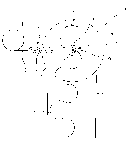
The sole figure of the drawing shows a schematically strongly
simplified illustration of the principle of a bending machine
1 according to the invention, which bending machine may
particularly be designed as a rope bending machine.

CA 02559466 2006-09-12
4
The bending machine 1 comprises a material feed device 2 which
advances or feeds material 6, particularly in the form of
wires or ropes, from a material reservoir 9 towards a bending
unit 3. The feed direction with a roll assembly 10 is
illustrated with arrow V in the drawing, which reveals that
the bending unit 3, viewed in this feed direction V, is
arranged behind the feed device 2.
The feed device 2 and the bending unit 3 are secured to a
support table 9, which is rotatably supported according to the
double-headed arrow DAT. To this end the support table 9
comprises a corresponding drive device, which is however not
shown in more detail in the figure.
In the example, the bending unit 3, in turn, comprises two
bending rolls 7 and 8 that are rotatably supported via a
further drive in accordance with the double-headed arrow DBR,
the bending direction of the material following from the
direction of the pivotal movement according to said double-
headed arrow.
Furthermore, the bending machine 1 is provided with a deposit
table 5 which is arranged to be stationary so that the support
table 4 can perform a relative rotation with respect to said
deposit table 5, which has the effect that the bent material
6' is oriented such that it comes to rest on the deposit table
5, which considerably increases the output of the bending
machine 1 according to the invention.

CA 02559466 2006-09-12
List of Reference Numerals
1 Bending machine
2 Feed device
3 Bending unit
9 Support table
Deposit table
6 Material (unbent)
6' Material (bent)
7 Bending rolls
8 Bending rolls
9 Material reservoir
Roll assembly of the feed device 2
V Feed direction
DAT Rotational direction of the support table 4
DHR Rotational direction of the bending rolls 7 and 8
Dessin représentatif
Une figure unique qui représente un dessin illustrant l'invention.
États administratifs

2024-08-01 : Dans le cadre de la transition vers les Brevets de nouvelle génération (BNG), la base de données sur les brevets canadiens (BDBC) contient désormais un Historique d'événement plus détaillé, qui reproduit le Journal des événements de notre nouvelle solution interne.

Veuillez noter que les événements débutant par « Inactive : » se réfèrent à des événements qui ne sont plus utilisés dans notre nouvelle solution interne.

Pour une meilleure compréhension de l'état de la demande ou brevet qui figure sur cette page, la rubrique Mise en garde , et les descriptions de Brevet , Historique d'événement , Taxes périodiques et Historique des paiements devraient être consultées.

Historique d'événement

Description Date
Inactive : Morte - Aucune rép. à lettre officielle 2009-03-12
Demande non rétablie avant l'échéance 2009-03-12
Réputée abandonnée - omission de répondre à un avis sur les taxes pour le maintien en état 2008-09-12
Inactive : Renseign. sur l'état - Complets dès date d'ent. journ. 2008-06-16
Inactive : Abandon. - Aucune rép. à lettre officielle 2008-03-12
Inactive : Lettre officielle 2007-12-12
Demande publiée (accessible au public) 2007-03-30
Inactive : Page couverture publiée 2007-03-29
Inactive : CIB en 1re position 2006-11-15
Inactive : CIB attribuée 2006-11-15
Inactive : Lettre de courtoisie - Preuve 2006-10-17
Demande reçue - nationale ordinaire 2006-10-12
Inactive : Certificat de dépôt - Sans RE (Anglais) 2006-10-12

Historique d'abandonnement

Date d'abandonnement Raison Date de rétablissement
2008-09-12

Historique des taxes

Type de taxes Anniversaire Échéance Date payée
Taxe pour le dépôt - petite 2006-09-12
Titulaires au dossier

Les titulaires actuels et antérieures au dossier sont affichés en ordre alphabétique.

Titulaires actuels au dossier
TRUMER SCHUTZBAUTEN GESMBH
Titulaires antérieures au dossier
DANIEL JAEGER
FRANZ OICHTNER
Les propriétaires antérieurs qui ne figurent pas dans la liste des « Propriétaires au dossier » apparaîtront dans d'autres documents au dossier.
Documents

Pour visionner les fichiers sélectionnés, entrer le code reCAPTCHA :


Pour visualiser une image, cliquer sur un lien dans la colonne description du document. Pour télécharger l'image (les images), cliquer l'une ou plusieurs cases à cocher dans la première colonne et ensuite cliquer sur le bouton "Télécharger sélection en format PDF (archive Zip)" ou le bouton "Télécharger sélection (en un fichier PDF fusionné)".

Liste des documents de brevet publiés et non publiés sur la BDBC .

Si vous avez des difficultés à accéder au contenu, veuillez communiquer avec le Centre de services à la clientèle au 1-866-997-1936, ou envoyer un courriel au Centre de service à la clientèle de l'OPIC.


Description du
Document 
Date
(aaaa-mm-jj) 
Nombre de pages   Taille de l'image (Ko) 
Abrégé 2006-09-11 1 9
Revendications 2006-09-11 1 21
Dessins 2006-09-11 1 12
Description 2006-09-11 4 105
Dessin représentatif 2007-03-13 1 5
Certificat de dépôt (anglais) 2006-10-11 1 159
Rappel de taxe de maintien due 2008-05-12 1 114
Courtoisie - Lettre d'abandon (lettre du bureau) 2008-06-03 1 165
Courtoisie - Lettre d'abandon (taxe de maintien en état) 2008-11-09 1 175
Correspondance 2006-10-11 1 26
Correspondance 2007-12-11 2 33