Note : Les descriptions sont présentées dans la langue officielle dans laquelle elles ont été soumises.
CA 02563899 2006-10-23
WO 2005/103305 PCT/AU2005/000576
- 1 -
METALLURGICAL PROCESSING INSTALLATION
TECHNICAL FIELD
The present invention relates to metallurgical
processing installations in which metallurgical processes
are performed within metallurgical vessels. The invention
has particular but not exclusive application to
installations used for performing direct smelting to
produce molten metal in pure or alloy form from a
metalliferous feed material such as ores, partly reduced
ores and metal-containing waste streams.
A known direct smelting process, which relies
principally on a molten metal layer as a reaction medium,
and is generally referred to as the Hlsmelt process, is
described in United States Patent 6267799 and
International Patent Publication WO 96/31627 in the name
of the applicant. The Hlsmelt process as described in
these publications comprises:
(a) forming a bath of molten iron and slag in a
vessel;
(b) injecting into the bath:
(i) a metalliferous feed material, typically
metal oxides; and
(ii) a solid carbonaceous material, typically
coal, which acts as a reductant of the metal
oxides and a source of energy; and
(c) smelting metalliferous feed material to metal in
the metal layer.
The term "smelting" is herein understood to mean
thermal processing wherein chemical reactions that reduce
metal oxides take place to produce liquid metal.
The Hlsmelt process also comprises
post-combusting reaction gases, such as CO and H2 released
from the bath, in the space above the bath with
oxygen-containing gas and transferring the heat generated
by the post-combustion to the bath to contribute to the
CA 02563899 2006-10-23
WO 2005/103305 PCT/AU2005/000576
2 -
thermal energy required to smelt the metalliferous feed
materials.
The Hlsmelt process also comprises forming a
transition zone above the nominal quiescent surface of the
bath in which there is a favourable mass of ascending and
thereafter descending droplets or splashes or streams of
molten metal and/or slag which provide an effective medium
to transfer to the bath the thermal energy generated by
post-combusting reaction gases above the bath.
in the Hlsmelt process the metalliferous feed
material and solid carbonaceous material is injected into
the metal layer through a number of lances /tuyeres which
are inclined to the vertical so as to extend downwardly
and inwardly through the side wall of the smelting vessel
and into the lower region of the vessel so as to deliver
the solids material into the metal layer in the bottom of
the vessel. To promote the post combustion of reaction
gases in the upper part of the vessel, a blast of hot air,
which may be oxygen enriched, is injected into the upper
region of the vessel through the downwardly extending hot
air injection lance. Offgases resulting from the
post-combustion of reaction gases in the vessel are taken
away from the upper part of the vessel through an offgas
duct.
The Hlsmelt process enables large quantities of
molten metal to be produced by direct smelting in a single
compact vessel. This vessel must function as a pressure
vessel containing solids, liquids and gases at very high
temperatures throughout a smelting operation which can be
extended over a long period. As described in United
States Patent 6322745 and International Patent Publication
WO 00/01854 in the name of the applicant the vessel may
consist of a steel shell with a hearth contained therein
formed of refractory material having a base and sides in
contact with at least the molten metal and side walls
extending upwardly from the sides of the hearth that are
in contact with the slag layer and the gas continuous
CA 02563899 2006-10-23
WO 2005/103305 PCT/AU2005/000576
3 -
space above, with at least part of those side walls
consisting of water cooled panels. Such panels may be of
a double serpentine shape with rammed or gunned refractory
interspersed between. Other metallurgical vessels have
been provided with internal refractories and refractory
cooling systems. In a conventional iron making blast
furnace for example, the cooling system generally
comprises a series of cooling staves of robust cast iron
construction capable of withstanding the forces generated
by the large quantities of burden extending upwardly
through the column of the blast furnace. These staves are
only replaced during a reline, during which the blast
furnace shuts down for an extended period. These days the
period between relines for a blast furnace which operates
continuously can be over twenty years and a reline extends
over a number of months.
Electric arc furnaces, such as those used for the
batch production of steel on the other hand, may employ
cooling panels which are simply suspended from a support
cage which can be accessed when the lid is removed and are
treated almost like consumables. They can be replaced
and/or repaired during other scheduled down times or
between heats.
The metallurgical vessel for performing the
Hlsmelt process presents unique problems in that the
process operates continuously, and the vessel must be
closed up as a pressure vessel for long periods, typically
of the order of a year or more and then must be quickly
relined in a short period of time as described in United
States Patent 6565798 in the name of the applicant. This
requires the installation of internal cooling panels in an
area to which there is limited access and a coolant flow
system which enables controlled flow of coolant to and
from the individual panels.
CA 02563899 2006-10-23
WO 2005/103305 PCT/AU2005/000576
4 -
DISCLOSURE OF THE INVENTION
The invention provides a metallurgical processing
installation comprising:
(a) a hollow metallurgical vessel;
(b) a plurality of cooling panels forming an
internal lining for at least an upper part of
the vessel, each panel having an internal
passage for flow of coolant therethrough;
(c) coolant inlet and outlet connectors for the
panels at locations distributed around the
exterior of the vessel; and
(d) a coolant flow system for flow of coolant to and
from the panel inlet and outlet connectors,
which flow system comprises a supply pipe and a
return pipe extending generally horizontally at
least partially around the vessel, a first
series of upright smaller pipes connected to the
main supply pipe and to the panel inlet
connectors and a second series of upright pipes
.20 connected to the return pipe and to the panel
outlet connectors.
The coolant flow system may be supported on a
tower structure at least partially surrounding the vessel.
The tower structure may be comprised of a
structural frame work of interconnecting columns and beams
and it may have walkways for access to the vessel and/or
the coolant flow system.
The main coolant supply pipe and the return pipe
may both be supported on an upper part of the tower
structure and the first and second series of smaller cross
section pipes may extend downwardly therefrom.
The supply pipe and return pipe may each be of
generally U-shaped configuration and disposed generally
about an upper end of the vessel.
The first and second series of upright pipes may
be connected to the panel inlet and outlet connectors via
respective individual inlet and outlet valves allowing for
CA 02563899 2006-10-23
WO 2005/103305 PCT/AU2005/000576
-
adjustment of the coolant flow to and from the panels
individually.
The connections to the panel inlet and outlet
connectors may be made by flexible couplings.
5 The metallurgical vessel may be fitted with a hot
gas injection lance for injecting hot gas downwardly in to
an upper part of the vessel, which lance is provided with
coolant flow passages, and the tower structure may also
support a gas lance coolant flow system for flow of
coolant to and from the coolant flow passages of the hot
gas injection lance.
The metallurgical vessel may also be fitted with
a series of solids injection lances for injection of
solids into a lower part of the vessel, which lances are
provided with coolant flow passages, and the tower
structure may also support a solids lance coolant flow
system for flow coolant to and from the coolant flow
passages of the solids injection lances.
BREIF DESCRIPTION OF THE DRAWINGS
In order that the invention may be more fully
explained, one particular embodiment will be described in
some detail with reference to. the accompanying drawings in
which:
Figure 1 is a vertical cross-section through a
direct smelting vessel provided with internal cooling
panels;
Figure 2 is a plan view of the vessel shown in
Figure 1;
Figure 3 illustrates the arrangement of cooling
panels lining a main cylindrical barrel part of the
vessel;
Figure 4 is a development of the cooling panels
shown in Figure 3;
Figure 5 is a development showing
diagrammatically the complete set of cooling panels fitted
to the vessel;
CA 02563899 2006-10-23
WO 2005/103305 PCT/AU2005/000576
6 -
Figure 6 is an elevation of one of the cooling
panels fitted to the cylindrical barrel section of the
vessel;
Figure 7 is a plan of the panel shown in
Figure 7;
Figure 8 is a cross-section on the line 8-8 in
Figure 6;
Figure 9 is a front view of the cooling panel
illustrated in Figure 6;
Figure 10 illustrates a detail of the cooling
panel;
Figures 11 and 12 illustrate details of the
connection of a cooling panel to the vessel shell;
Figure 13 illustrates a vessel access tower which
extends about the direct smelting vessel in a direct
smelting plant and which is provided with coolant flow
systems for flow of coolant to and from the cooling panels
of the vessel and to other equipment fitted to the vessel;
Figure 14 further illustrates the construction of
the vessel access tower;
Figure 15 illustrates the vessel and a part of
the coolant flow systems on the access tower; and
Figure 16 illustrates the coolant flow systems
with the vessel removed; and
Figures 17a and 17b provide a pictorial
representation of the vessel in combination with the
access tower and the coolant flows systems
DETAILED DESCRIPTION OF THE PREFERRED EMBODIMENT
Figures 1 and 2 illustrate a direct smelting
vessel suitable for operation of the Hlsmelt process as
described in United States Patent 6267799 and
International Patent Publication WO 96/31627. The
metallurgical vessel is denoted generally as 11 and has a
hearth 12 which includes a base 13 and sides 14 formed of
refractory bricks, a forehearth 15 for discharging molten
CA 02563899 2006-10-23
WO 2005/103305 PCT/AU2005/000576
7 -
metal continuously and a tap hole 16 for discharging
molten slag.
The base of the vessel is fixed to the bottom end
of an outer vessel shell 17 made of steel and comprising a
cylindrical main barrel section 18, an upwardly and
inwardly tapering roof section 19, and an upper
cylindrical section 21 and lid section 22 defining an
offgas chamber 26. Upper cylindrical section 21 is
provided with a large diameter outlet 23 for offgases and
the lid 22 has an opening 24 in which to mount a
downwardly extending gas injection lance for delivering a
hot air blast into the upper region of the vessel. The
hot gas injection lance is internally water cooled, being
provided with inner and outer annular coolant flow
passages for inward and outward flow of cooling water.
More particularly, this lance may be of the general
construction disclosed in United States Patent 6440356.
The main cylindrical section 18 of the shell has
eight circumferentially spaced tubular mountings 25
through which to extend solids injection lances for
injecting iron ore, carbonaceous material, and fluxes into
the bottom part of the vessel. The solids injection lances
are also internally water cooled, being provided with
inner and outer annular coolant flow passages for inward
and return flows of cooling water. More particularly, the
solids injection lances may be of the general construction
disclosed in United States Patent 6398842.
In use the vessel contains a molten bath of iron
and slag and the upper part of the vessel must contain hot
gases under high pressure and extremely high temperatures
of the order of 1200 C. The vessel is therefore required
to operate as a pressure vessel over long periods and it
must be of robust construction and completely sealed.
Access to the interior of the vessel is extremely limited,
access essentially being limited on shut down through lid
opening 24 and reline access doors 27.
CA 02563899 2006-10-23
WO 2005/103305 PCT/AU2005/000576
8 -
Vessel shell 11 is internally lined with a set of
107 individual cooling panels through which cooling
water can be circulated and these cooling panels are
encased in refractory material to provide a water cooled
internal refractory lining for the vessel above the
smelting zone. It is important that the refractory lining
be virtually continuous and that all of the refractory
material be subject to cooling as uncooled refractory will
be rapidly eroded. The panels are formed and attached to
the shell in such a way that they can be installed
internally within the shell 11 and can be removed and
replaced individually on shut down without interfering
with the integrity of the shell.
The cooling panels consist of a set of
forty-eight panels 31 lining the main cylindrical barrel
section 18 of the shell and a set of sixteen panels 32
lining the tapering roof section 19. A first set of four
panels 33 line a lower part of the off-gas chamber 26
immediately above the tapering roof section 19. Twenty
panels 34 line the section of the off-gas chamber 26 above
the first set of four panels 33. Eleven panels 35 line
the lid 22 and eight panels 40 line the outlet 23.
The panels of the off-gas chamber and the lowest
row of panels in the barrel section are formed from a
single layer of pipes, whereas the remaining panels of the
barrel section 31 and also of the tapering roof section 19
are formed from a double layer of pipes, disposed one in
front of the other relative to the vessel shell 17. The
lowest row of panels 31 in the barrel section are located
behind the refractory of the hearth and are closest to the
molten metal. In the event of significant refractory
erosion or spalling there is potential for these panels to
contact molten metal and therefore are preferably
constructed of copper. The remaining panels in the barrel
section and also the off-gas chamber 26 may be constructed
of steel.
CA 02563899 2006-10-23
WO 2005/103305 PCT/AU2005/000576
9 -
The construction of panels 31 and the manner in
which they are mounted on the main cylindrical barrel 18
of the vessel shell is illustrated in Figures 6-12. As
shown in Figure 3, 4 and 5, these panels are disposed in 6
vertically spaced tiers of arcuate panels spaced
circumferentially of the vessel, there being eight
individual panels 31 in each tier. Each panel 31 is
comprised of a coolant flow tube 36 bent to form inner and
outer panel sections 37, 38 of zigzag formation. The
inner and outer panel sections 37, 38 are also vertically
off-set such that the horizontal pipe segments of one
panel section are located intermediate the horizontal pipe
segments of the other panel section. Coolant inlet and
outlet tubular connectors 42 extend from the inner panel
section at preferably one end of each panel, though they
may also extend from other sections of, or locations on,
the panel.
,Panels 31 are of elongate arcuate formation
having greater length than height and with a curvature to
match the curvature of the main cylindrical barrel section
18 of the shell. As may be seen from Figures 3 & 4 a
series of apertures 55 are formed within the set of barrel
panels 31. These apertures 55 align with the
circumferentially spaced tubular mountings 25 and operate
to provide clearance sufficient for solids injection
lances to penetrate into the interior of the vessel 11.
Typically the apertures are shaped so as to accommodate
generally cylindrical solids injection lances that extend
through the vessel shell 17 and the panels 31 so as to
form an angle to a vertical plane tangential to the vessel
shell 17 at the centre point of the penetration. The
apertures 55 are formed by alignment of two or more panels
having, recesses formed along an edge. The recesses may
be along vertical or horizontal edges or may be at one or
more corners. The tubular mountings 25 are spaced
circumferentially of the vessel at a common height. The
panels that form apertures 55 are of a length
CA 02563899 2006-10-23
WO 2005/103305 PCT/AU2005/000576
- 10 -
corresponding to the circumferential distance between
tubular mountings 25 such that typically the centre line
of each lance is aligned with the vertical edge of two or
more adjacent panels. This arrangement results in the
panels in the region of the solids injection lances having
recesses along both vertical edges. These recesses may
extend to the upper or lower corner of the panel.
A set of four mounting pins 43 are connected to
the zigzag tubular formation of the outer panel section 38
by means of connector straps 44 so as to project laterally
outwardly from the panel. Each connector strap 44 is
fastened at its ends to adjacent tube segments of the
inner panel section and extends between its ends outwardly
across a tube segment of the outer panel section in the
manner shown most clearly in Figure 10. The connector
straps 44 are generally V-shaped with the root of the
V-shape curved to fit snugly about the tube segment of the
outer panel section. The pins 43 are welded to the
connector straps so as to extend outwardly from the roots
of the V-shapes. The connecting straps serve to brace the
panels by holding the tube segments securely in spaced
apart relationship at multiple locations distributed
throughout the panels, resulting in a strong but flexible
panel construction.
The mounting pins 43 are extended through
openings 45 in the shell 17 and tubular protrusions 46
surrounding the openings 45 and protruding outwardly from
the shell 17. The ends of pins 43 project beyond the
flanges 57 located at the outer ends of the tubular
protrusions 46. The pins 43 are connected to the flanges
57 by welding annular metal discs 47 to the pins 43 and
the flanges 57 thus forming connections exteriorly of the
shell in a way which seals the openings 45.
In similar fashion the inlet and outlet
connectors 42 for the panel project outwardly through
openings 48 in the shell 17 and through and beyond tubular
protrusions 49 surrounding those openings and protruding
CA 02563899 2012-01-10
11 -
outwardly from the shell and connections are made by
welding annular discs 51, between the connectors 42 and
flanges 59 located on the extremity of the protrusions 49.
In this way, each panel 31 is mounted on the shell through
the four pins 43 and the coolant connectors 42 at
individual connections exteriorly of the'shell. The pins
and coolant connectors are a clearance fit within the
tubular protrusions tubes 46, 49. The protrusions 46, 49,
the flanges 57, 59, the discs 47 and the pins 43 are rigid
and have sufficient strength to support the load of the
panels in a cantilevered manner from the extremity of the
protrusions when the panels are operational and hence
filled with cooling water and encased in refractory.
The panels 31 are removed by grinding the weld
between the pins 43 and the flanges 57 and between the
coolant connectors 42 and the flanges 59. In this way the
panels are readily removed. The flanges 57, 59 may also
be removed by grinding before replacement panels are
installed. This method allows the panels to be removed
with limited damage to the flanges 57, 59, the protrusions
46, 49 and hence the vessel 11.
The pins 43 and the coolant inlet and outlet
connectors 42 are oriented so as to project laterally
outwardly from the panel in parallel relationship to one
another and so as to be parallel with a central plane
extended laterally through the panel radially of the
vessel so that the panel can be inserted and removed by
bodily movement of the panel inwardly or outwardly of the
cylindrical barrel of the vessel.
The gaps 53 between the circumferentially spaced
panel 31 must be sufficient to enable the trailing outer
edges of a panel being removed to clear the inner edges of
the adjacent panels when the panel to be removed is
withdrawn inwardly along the direction of the pins 43 and
connectors 42. The size of the gaps required is dependant
on the length of the arcuate panels and therefore the
number of panels extending the circumference of the barrel
CA 02563899 2006-10-23
WO 2005/103305 PCT/AU2005/000576
- 12 -
section 18. In the illustrated embodiment there are eight
circumferentially spaced panels in each of the six tiers
of panels 31. It has been found that this allows minimal
gaps between the panels and ensures proper cooling of
refractory material at the gaps. Generally for
satisfactory cooling it is necessary to divide each tier
into at least six circumferentially spaced panels.
Additionally, the arcuate length of an outer panel section
may be less than the arcuate length of an inner panel
section. Such an arrangement allows the gap 53 between
the inner panel section of adjacent panels to be minimised
compared with an arrangement where the outer panels
section and inner panel section are of the same length.
Refractory retainer pins 50 are butt welded to
the coolant tubes of panels 31 so as to project inwardly
from the panels and act as anchors for the refractory
material sprayed out the panels. Pins 50 may be arranged
in groups of these pins radiating outwardly from the
respective tube and arranged at regular spacing along the
tube throughout the panel.
The panels 33 and 34, being fitted to
cylindrically curved sections of the vessel, are formed
and mounted in the same fashion as the panels 31 as
described above, but some of the panels 34 are shaped in
the manner shown in Figure 5 so as to fit around the
offgas outlet 23.
The panels 32 and 35, being fitted to tapered
sections of the shell, are generally conically curved in
the manner shown in the illustrated development of
Figure 5 except for this variance in shape. However,
these panels are also formed and mounted to the shell in
similar fashion to the panels 31, each being fitted with
mounting pins projecting laterally outwardly from the
panel and a pair of inlet/outlet coolant connectors at
opposite ends of the panels, the pins and connectors being
extended through openings in the shell and connected to
tubes projecting laterally outwardly from the shell to
CA 02563899 2006-10-23
WO 2005/103305 PCT/AU2005/000576
- 13 -
form connections exteriorly of the shell which seal the
openings and provide a secure mounting for the panels
while permitting some freedom of movement of the panels.
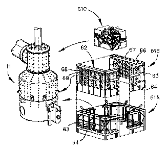
Figures 13 to 16, together with Figures 17a and
17b illustrate a vessel access tower 61 designed to fit
around the vessel 11 and fitted with a coolant flow system
62 to provide for flow of cooling water to and from the
cooling panels 31, 32, 33, 34 and 35 within the vessel and
two separate coolant flow systems 81, 82 for flow of
cooling water to the coolant flow passage of the hot gas
injection lance at the upper end of the vessel and to the
coolant flow passageway of the solids injection lances
spaced circumferentially around the vessel.
Tower 61 is formed in three modules 61A, 61B and
61C which are installed one on top of the other and welded
together on installation at the direct smelting plant
site. The tower is comprised of a structural framework of
columns 63 and beams 64 which carry the coolant flow
systems 62, 81 and 82 and walkways 65 providing access to
the vessel and the coolant flow systems.
The coolant flow system 62 includes water supply
and return piping comprising large diameter main supply
and return pipes 66, 67 mounted on an upper part of tower
61 to extend around the upper end of vessel 11, a first
series of vertical dropper pipes 68 of relatively small
diameter connected to the main water supply pipe 66 and
extending downwardly to connections with the water inlet
connectors for the respective cooling panels of the
vessel, and a second series of smaller diameter vertical
pipes 69 connected at their upper ends to the main return
pipe 67 and at their lower ends to individual outlet
connectors for the cooling panels in the vessel. Thus the
vertical pipes 68 provide for separate flows of water from
the main supply pipe to individual panels and the pipes 69
provide for independent return flow of water from the
outlets of the individual panels. The lower ends of the
vertical pipes 68, 69 are connected to the respective
CA 02563899 2012-01-10
- 14 -
panel inlet and outlet connectors via horizontal pipe ends
which extend inwardly to the respective connectors and are
connected to them via flexible couplings.
The vertical pipes 68 supplying individual water
flows to the panels are provided with `individual flow
control valves 71 and the vertical pipes 68 providing
individual return flows from the panels are provided with
individual flow control valves 72 so that both the input
and output flows of each panel of each cooling panel can
be adjusted. This allows for fine tuning of the flows
through all of the panels and control of cooling
throughout the vessel.
The vertical water flow pipes 68, 69 are arranged
in adjacent pairs in a sheet-like array around the tower
61 and the flow control valves 71, 72 are grouped in
arrays extending generally horizontally around the tower
in the vicinity of horizontal walkways on the tower so
that they are readily accessible by walking around the
walkways. The valves are arranged sequentially around the
vessel in the same order as the respective cooling panels
to which they relate so that the relationship between the
valves and the related part of the vessel is readily
apparent.
Coolant flow system 81 provides for flow of water
to and from the coolant flow passageway the hot gas
injection lance at the upper end of the vessel. As seen
in Figures 15 and 16, coolant flow system 81 includes main
supply and return pipes 83, 84 mounted on an upper part of
tower 61 and which are connected by smaller branch pipes
85 to respective connections on the hot air injection
lance assembly 86.
Coolant flow system 82 provides for flow of water
to and from the coolant flow passage of the solids
injection lances spaced circumferentially around the
vessel. It may also provide cooling water for cooling the
slag notch of the vessel. As seen in Figures 15 and 16,
coolant flow system 82, comprises main supply and return
CA 02563899 2006-10-23
WO 2005/103305 PCT/AU2005/000576
- 15 -
pipes 87, 88 which are connected by branch pipes to the
respective connectors on the solids injection lances and
to cooling water passageways at the slag notch.
Figures 17a and 17b provide a pictorial
representation of vessel 11 in combination with the access
tower 61 and the coolant flow systems 62, 81 and 82. In
particular, off-gas chamber 26, roof section 19 and an
upper portion of barrel section 18 of vessel 11 may be
seen along with a portion of the hot gas injection lance
and a hot gas supply main 100, that supplies hot gas to
the hot gas injection lance.
The access tower 61 comprises an inner periphery that
is located adjacent the vessel 11 and an external
periphery that is laterally displaced from the inner
periphery. A number of walkways 65 extend between the
inner periphery and the external periphery and provide
personnel with access to the vessel 11, equipment located
on the vessel 11, the coolant flow systems 61 and 82 and
flow control valves 71 & 72. Additional walkways are
provided above the roof section 19 of the vessel and
provide access to the hot gas injection lance, its
associated cooling system 82 and the hot gas supply main
100.
The walkways 65 extending between the inner and outer
peripheries of the access tower 61 include an off-gas
chamber control and monitoring walkway 65a, a barrel
control and monitoring walkway 65b and a lance control and
monitoring walkway 65c. Cooling to the off-gas chamber 26
of the vessel 11 is monitored and controlled from the off-
gas chamber control and monitoring walkway 65a. Cooling
to the barrel section 18 of the vessel 11 is monitored and
controlled from the barrel control and monitoring walkway
65b. Cooling to the lances and ancillary equipment is
controlled from the lance control and monitoring walkway
65c.
The off-gas chamber monitoring and control walkway
65a is located adjacent the roof section 19 of the off-gas
CA 02563899 2006-10-23
WO 2005/103305 PCT/AU2005/000576
- 16 -
chamber 26. The main supply and return pipes 66 & 67 are
located above both the roof section 19 and the off-gas
chamber control and monitoring walkway 65a. The barrel
control and monitoring walkway 65b is the walkway
immediately below the off-gas chamber control and
monitoring walkway 65a. The lance control and monitoring
walkway 65c is the walkway immediately below the barrel
control and monitoring walkway 65b. Additional walkways
are located below the lance control and monitoring walkway
65c, such as a lance access walkway 65d that allows
personnel to access the solids injection lances along with
a cast house floor 65e and an end tap floor 65f.
A raw materials conveying region is located adjacent
the solids injection lances and the inner periphery of the
access tower. It extends between the lance control and
access walkway 65c and the barrel control and access
walkway 65b.
Main supply and return pipes 66 and 67 of coolant
flow system 62 operate as header pipes and, as detailed
above, are located above the roof section 19 of the vessel
11. Main supply and return pipes 87, 88 of coolant flow
system 82 also operate as header pipes and are typically
located adjacent the inner periphery of access tower 61
around a mid section of off-gas chamber 26, between the
barrel control and monitoring walkway 65b and the off-gas
chamber control and monitoring walkway 65a.
The coolant flow system 62 supplies cooling water to
the water cooled panels depicted in Figure 5 that are
distributed on the shell of the vessel 11 between a lower
region of the vessel adjacent the hearth and the roof
section 19 of the vessel 11. The coolant flow system 82
supplies cooling water to solids injection lances that
supply raw materials to the vessel 11 during operation and
also to other ancillary equipment such as a slag notch
through which slag is tapped during operation. The
coolant flow system 62 for the water cooled panels
operates at a different cooling water pressure to the
CA 02563899 2006-10-23
WO 2005/103305 PCT/AU2005/000576
- 17 -
coolant flow system 82 for the solids injection lances and
the ancillary equipment. The headers for the coolant flow
system 82 for the solids injection lances and ancillary
equipment are located below the headers for the coolant
flow system 62 for the water cooled panels.
Water flow pipes 68, 69 of coolant flow system 62
that extend between the main supply and return pipes 66 &
67 and the water cooled panels are, at least in part,
distributed across the external periphery of the access
tower. Water flow pipes of the coolant flow system 82
that extend between the main supply and return pipes 87 &
88 and the water cooled injection lances and ancillary
equipment are primarily distributed across the inner
periphery of the access tower.
As can be seen from Figure 5, a typical embodiment
provides in the order of 100 water cooled panels supported
by vessel 11. This results in a large number of coolant
flow pipes distributed across the access tower 61 between
the main supply and return pipes 66 & 67 and the water
cooled panels.
Water flow pipes 68 & 69 are distributed, at least in
part, across the external periphery of the access tower.
In order to connect.with the water cooled panels, the
coolant flow pipes 68 & 69 are routed from the external
periphery to the inner periphery in a staged manner. For
example, only those water flow pipes that connect to water
cooled panels located in the upper region of the vessel
(such as the off-gas chamber 26) extend directly from main
supply and return pipes 66 & 67. The remainder extend
across the external periphery of the access tower 61
before being routed back to the inner periphery. This
reduces over crowding of pipe work adjacent the inner
periphery of the access tower, at least in the vicinity of
the upper region of the vessel 11.
The pipes that connect to water cooled panels located
on the middle and lower regions of the vessel extend from
the main supply and return pipes 66 & 67 along the
CA 02563899 2006-10-23
WO 2005/103305 PCT/AU2005/000576
- 18 -
external periphery of the access tower 61. In this regard
they extend across the external periphery substantially
parallel to the upper region of the vessel 11 and hence
substantially parallel to the pipes extending along the
inner periphery of the access tower 61 adjacent the upper
region of the vessel and connecting to water cooled panels
located in this upper region. These pipes on the external
periphery are then routed to the inner periphery from a
position on the access tower that is in the vicinity of
the middle region of the vessel. Pipes connecting to
water cooled panels located below the middle section of
the vessel may also extend along the external periphery of
the access tower, substantially parallel to the upper and
middle section of the vessel, and be routed to the inner
periphery of the access tower from a position in the
vicinity of the lower region.
Thus the water flow pipes extending to the upper
sections of the vessel 11 and the water flow pipes
extending to the middle and lower sections of the vessel
11, extend in a generally parallel manner along the inner
and outer periphery of the access tower and are laterally
spaced by walkways, such as the off-gas chamber control
and monitoring walkway 65a. This arrangement typically
allows that only those pipes that are to be connected to
water cooled panels located in a particular area of the
vessel 11 (such as the off-gas chamber 26) are located at
the inner periphery of the access tower in the particular
area of concern. Pipes that extend past this area and
that are connected to a lower area of the vessel 11 are
located on the external periphery. This arrangement for
the staged routing of pipes to the inner periphery of the
access tower 61 helps reduce over crowding of coolant flow
pipes adjacent the upper areas of the vessel 11 which
would otherwise have all or a large portion of the coolant
flow pipes extending past their surface if all of the
water flow pipes were routed along the inner periphery of
the access tower.
CA 02563899 2006-10-23
WO 2005/103305 PCT/AU2005/000576
- 19 -
Typically the pipes are routed in groups from the
external periphery to the inner periphery of the access
tower adjacent the underneath surface of the walkways.
For example, pipes for the upper section of the barrel may
be routed underneath the barrel control and monitoring
platform 65b, whereas pipes for a lower section of the
vessel may be routed underneath the lance control and
monitoring walkway 65c, the lance access walkway 65d and
possibly the cast house floor 65e. This ensures the
walkways provide clear access for personnel that is
substantially free from water supply pipes.
Alternate embodiments may locate an additional set of
header pipes between the lance access walkway 65d and the
lance control and monitoring walkway 65c. The header
pipes are raised off of the lance access walkway 65d
toward the under surface of the lance monitoring and
control walkway 65c. These header pipes service the water
cooled panels located in the lower region in the vessel 11
adjacent the hearth. Typically they service the lower two
rows of water cooled panels.
These additional header pipes are located at an
external periphery of the lance access walkway 65d and the
water flow pipes that extend off of these headers extend
vertically to below the lance access walkway 65d and then
are routed either underneath the lance access walkway 65d
to their connection point with a water cooled panel or
extend to below the cast house floor from where they are
routed to their connection with a water cooled panel.
Control valves 71 & 72 are located on the vertical section
of these pipes adjacent the lance access walkway 65d so
that the lower rows of the water cooled panels are
controlled from a single location.
As detailed above, water flow pipes of the coolant
flow system 62 that extend between the main supply and
return pipes 66 & 67 and the water cooled panels are
divided into two groups. A first group extends
horizontally from the headers 66 & 67 toward the inner
CA 02563899 2006-10-23
WO 2005/103305 PCT/AU2005/000576
- 20 -
periphery of the access tower 61 and then drop vertically,
adjacent the inner periphery of the access tower 61, in
order to connect to the water cooled panels located on the
off-gas chamber 26. A large portion of these pipes extend
below the off-gas chamber control and monitoring walkway
65a and are then routed adjacent the underneath surface of
this walkway to a location. aligned with the required water
cooled panel. Once aligned, the pipes extend vertically
again from the underneath surface of the walkway 65a to
the location on the off-gas chamber of the inlet or outlet
pipe of the water cooled panel of interest.
Control valves 71 & 72 and other monitoring and
control equipment for the water cooled panels located in
the upper region of the vessel are typically located at a
position above walkway 65a-(i.e. on the vertical sections
of the water flow pipes servicing the water cooled panels
of the off-gas chamber). This location of the control
valves 71 & 72 enables personnel standing on platform 65a
to monitor and control the cooling of the off-gas chamber
from a single walkway.
The second group of water flow pipes 68 & 69 of the
coolant flow system 62 for the water cooled panels extend
from the main supply and return pipes 66 & 67 to the
external periphery of the access tower 61. This second
group forms a sheet like array of pipes that extends
vertically down at least a part of the external periphery
of the access tower 61. In order to connect to the water
cooled panels, these pipes also extend between the
external periphery and the inner periphery of the access
tower 61 in a horizontal manner. In this regard each pipe
extends underneath one of the various walkways 65 and is
routed, adjacent the underneath surface of the walkway,
toward the inner periphery of the access tower 61 and is
aligned with the cooling panel of interest. For example,
pipes that are to be connected to an upper section of the
barrel 18 of the vessel typically extend underneath the
barrel control and monitoring walkway 65b and pipes to be
CA 02563899 2006-10-23
WO 2005/103305 PCT/AU2005/000576
- 21 -
connected to a lower section of the barrel 18 of the
vessel may extend under the lance control and monitoring
walkway 65c. Underneath the walkways the pipes are routed
to a location aligned with the required water cooled
panel. Once aligned, the pipes extend vertically again,
typically from adjacent the underneath surface of the
walkway to the location on the vessel 11 of the inlet or
outlet of the water cooled panel of interest.
A typical embodiment has eight lances and one slag
notch and so the number of water flow pipes distributed
from the main supply pipes 87 & 88 across the inner
periphery of the vessel is substantially less than the
number of water flow pipes with the water cooled panels.
Accordingly, location of the main supply pipes 87 & 88
adjacent the inner periphery of the access tower does not
lead to over crowding of the surface of the vessel by
coolant flow pipes.
The raw materials conveying region is located
adjacent the solids injection lances. Raw materials
conveying apparatus extend laterally through the raw
materials conveying region, from adjacent the external
periphery of the access tower to connect with the solids
injection lances adjacent the inner periphery of the
access tower.
The water flow pipes for the coolant panels of the
vessel adjacent the raw materials conveying region are
distributed across the inner periphery of the access
tower. Similarly the water flow pipes for the solids
lances are also distributed across the inner periphery of
the access tower. Thus the external periphery of the
access tower adjacent the raw materials conveying region
is substantially free of water flow pipes. This provides
for relatively unimpeded access to the raw materials
conveying apparatus and the solids injection lances.
The supply and return pipes for any particular piece
of water cooled equipment are typically located adjacent
each other. This allows the control valves 71, 72 and
CA 02563899 2006-10-23
WO 2005/103305 PCT/AU2005/000576
- 22 -
other control or monitoring devices for each piece of
water cooled equipment to be located in close proximity to
each other for ease of operation. Where the supply and
return pipes extend down the external periphery of the
tower, the control valves 71 & 72 and other control or
monitoring equipment are typically located on the vertical
section of the pipes adjacent one of the walkways 65.
This enables the control valves and other monitoring
equipment to be located on the external periphery of the
access tower 61 for access by personnel located on the
walkway of interest. Where the supply and return pipes
are associated with main supply and return pipes 87 & 88
for the solids injection lances and the ancillary
equipment, the control valves and other control or
monitoring equipment are located adjacent the inner
periphery of tower 61 on the lance control and monitoring
walkway 65c
This arrangement allows the control valves and other
monitoring equipment for the water cooled equipment
located in specific regions of the vessel (such as the
off-gas chamber 26, the barrel 18) or arranged in specific:
groups or separate cooling water circuits (such as the
solids injection lances) to be grouped together in close
proximity for ease of operation. For example, the control
valves and other monitoring equipment for the off-gas
chamber 26 are located adjacent to and are accessible from
the off-gas control and monitoring platform 65a. As these
water flow pipes extend from the main supply and return
pipes 66 & 67 directly along the inner periphery of the
access tower, the control valve and other monitoring
equipment on the off-gas control and monitoring platform
are located adjacent the inner periphery of the access
tower 61. The control valves and other monitoring
equipment for the water cooled panels located on the
barrel 18 are located adjacent to and are accessible from
the barrel control and monitoring platform 65b. These
water flow pipes extend along the external periphery of
CA 02563899 2006-10-23
WO 2005/103305 PCT/AU2005/000576
- 23 -
the access tower before extending underneath the barrel
control and monitoring platform 65b (or a platform lower
down on the access tower) and the control valves and other
monitoring equipment are located adjacent the external
periphery of the access tower 61. The control valves and
other monitoring equipment for the solids injection lances
and other ancillary equipment are located adjacent to and
are accessible from the lance control and monitoring
platform 65c. The water flow pipes for the solids
injection lances and other ancillary equipment are
distributed across the inner periphery of the access
tower. Accordingly the control valves and other
monitoring equipment for solids injection lances and other
ancillary equipment are located adjacent the inner
periphery of the access tower.
Whilst the embodiment detailed above provides control
valves and other monitoring equipment for different
regions of the vessel on different walkways, it is
possible for control valves for different regions to be
located on the same walkway. For example, the control
valves and monitoring equipment for off-gas chamber 26 and
barrel 18 may be located adjacent the same walkway as
these control valves would be located on the inner
periphery and the external periphery respectively.
The illustrated equipment has been advanced by
way of example only. The physical construction of the
vessel and the cooling panels could be varied as could the
detailed construction of the coolant supply system and the
manner in which it is supported about the vessel. It is
to be understood that such variations can be made without
departing from the scope of the appended claims.