Note : Les descriptions sont présentées dans la langue officielle dans laquelle elles ont été soumises.
CA 02565404 2006-11-02
WO 2005/110724 PCT/US2005/011735
METHOD OF SEALING A SUMP
This invention relates to underground piping systems, and specifically
to a method for lining and sealing a sump that is mounted on an
underground, liquid storage tank.
Background
Sumps are widely used in the field of secondary containment for the
underground transfer of hazardous fluids including gasoline and diesel
fuels. Sumps are prefabricated chambers that are commonly placed on top
of a fluid storage tank and beneath a manhole cover in a gas station. The
sumps allow access to the piping equipment. In a pressure system, the
sump typically houses a portion of a pump and its associated piping fittings.
In a suction system, the sump does not house a pump, but it will typically
include fuel piping. The sump generally has through-wall openings to
permit the passage of pipes going into the tank and through the side wall of
the sump. These openings may have gaskets or bulkhead fittings to form a
fluid tight seal about the pipe and to prevent ground water from leaking into
the sump. In addition to keeping ground water out of the sump chamber,
the sump is intended to prevent the escape of a leaked, hazardous fluid into
the environmental soil.
Many sumps may develop leaks as a result of improper installation,
degradation of seals, ground water hydrostatic pressure, or other reasons.
-1-
CA 02565404 2006-11-02
WO 2005/110724 PCT/US2005/011735
Typically, leaky sumps must be repaired by excavation tecn.niques znaL i;uc
necessary to completely replace a sump or at least replace a portion thereof.
This type of repair is extremely time consuming and expensive.
Another type of repair of sumps is described in U.S. Patent No.
5,870,871. In the repair method described therein, a plurality of film and
pieces are placed inside the sump to create a liner substantially conforming
to the interior dimensions of the sump. The pieces are joined together to
form a unitary containment shell. A problem with this method is the
difficulty with proper installation of the pieces of liner.
Summary
Accordingly it is an object of the present invention to overcome the
foregoing problems and provide a liner for a sump. The liner is a coating of
elastomeric material that is sprayed onto the surface of the sump to create a
durable and fluid tight seal.
In one embodiment, a method of lining a sump comprises applying
elastomeric material to a surface of the sump by spraying the elastomeric
material onto a surface of the sump whereby a continuous elastomeric
coating is formed on the surface. The elastomeric coating is then allowed to
cure whereby an elastomeric liner is formed on the surface to seal the sump.
The surface of the sump may be pre-treated by mechanical roughing of the
surface of the sump prior to the coating step. Also, the surface of the sump
may be pre-treated by heating of the surface of the sump. The heating and
-2-
CA 02565404 2006-11-02
WO 2005/110724 PCT/US2005/011735
mechanical roughing steps may both be used to pre-treat tne suriace ul Li1G
sump, and the heating step may take place before the step of roughing of
the surface. The elastomeric material may be a polyurethane polymer, and
it may be coated to a thickness of from about 1/8 of an inch to about 1/ 4 of
an inch. The spraying step may comprise spraying the elastomeric material
over substantially the entire interior surface of the sump or, alternatively,
over a portion of or the entire the exterior surface of the sump.
In another example, an assembly includes a sump and a coating, the
assembly comprising a sump having side walls and forming part of an
underground piping system. The sump comprises an opening in one
sidewall for permitting passage of a pipe. The assembly includes a sprayed-
on elastomeric coating on at least the one sidewall comprising an opening
therein, wherein the elastomeric coating forms a seal around the opening to
create a fluid tight chamber within the sump. The sump may comprise a
plurality of openings adapted to permit passage of a plurality of pipes. The
elastomeric coating may cover substantially the entire inside of the sidewalls
of the sump. The thickness of the coating may be from about 1/8 of an inch
to about 1/4 of an inch. The elastomeric coating may be a polyurethane
polymer.
Brief Description of the Drawings
Figure 1 is a side elevation, cross sectional view of a sump mounted
onto a fluid tank as shown in an underground environment.
-3-
CA 02565404 2006-11-02
WO 2005/110724 PCT/US2005/011735
Figure 2 is a side elevation view ot the sump as snown in r igurc 1
further displaying an elastomeric coating.
Figure 3 is a side elevation view of the sump shown in Figure 1 further
illustrating an elastomeric coating over the entire surface of the inside of
the
sump.
Figure 4 is a perspective, cut away view of a sump showing a pipe
extending through the sidewall of the sump.
Figure 5 is a perspective view of the sump shown in Figure 4 wherein
the inside surface of the sump around the pipe has been sprayed with an
elastomeric coating.
Detailed Description
Figures 1-5 illustrate various alterative examples of a prior art sump
(Figure 1) and a sealed sump as described herein. The focus of each
example is the use of a sprayed-on polymer to seal or reenforce the sump,
thereby enhancing its fluid tight attributes.
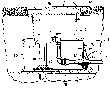
Figure 1 shows a sump 10 that is mounted on the wall 12 of an
underground storage tank. The sump 10 is buried in dirt or gravel 14. In a
traditional gas station setting, the sump 10 is mounted underneath
pavement or concrete 16. Access to the sump 10 is available through a
manhole cover 18 that is mounted onto a manhole ring 20 that is fixed in
the pavement or concrete 16.
-4-
CA 02565404 2006-11-02
WO 2005/110724 PCT/US2005/011735
The sump 10 is made up of a sidewal125 tnat cteiines a cnamuca z, i
therein. The sump 10 has an opening 31 that is covered by a lid 30 that is
in a sealing engagement with the sump opening 31. The sidewall 25 of the
sump 10 includes an opening 35 in which is mounted a fitting 36 and plate
37 that passes through the sidewall 25. The fitting 36 is of a material and
fit in order to create a seal of the opening 35 in the sidewall 25. Inside the
sump chamber 27, there is shown a pump 42 that includes a pipe 40 and
pipe fittings 41 that feed down into a fluid storage tank through the fluid
storage tank wall 12.
The foregoing description of a sump installation is a typical
construction. As noted earlier, the fitter 36 and 41 may deteriorate over
time or they may have been improperly installed to allow liquid seepage into
an out of the cavity 27 of the sump 10. Still further, the sidewalls 25 of the
sump 10 may deteriorate over time or have been damaged during
installation or maintenance so that cracks or other weak points develop that
may likewise be a source of seepage of fluid into or out of the chamber 27.
Figure 2 illustrates a sump 10 that is essentially the same as the
sump shown in Figure 1 except that there are areas where a polymer has
been coated onto the surface of the sidewalls 25. As shown in Figure 2, a
spray-on elastomeric material is shown on the inside surface 50 and the
outside surface 51 around the opening 35 where the pipe passes through
the sidewall 25. Also, the spray-on polymer is shown being coated around
the fitting 41 where the pipe 40 passes through the sidewall 25 in
-5-
CA 02565404 2006-11-02
WO 2005/110724 PCT/US2005/011735
connecting the fluid storage tank to the sump 1 u. Rs snown in r lgu~ u Z',
U1x;
spray-on coating is on the inside and outside of the sump sidewalls 25
around the opening 35. Of course, the coating may be effectively used on
just the outside 51 or just the inside 50. Such a coating would also be
effective if there was another known leakage point in the sump, for instance
where a wall was damaged during installation or maintenance. Specific
weak spots may be coated with a spray-on polymer to further sure the fluid
tight attribute of the sump 10.
In Figure 3, the entire inside of the sidewalls 25 of the sump 10 are
coated with polymer 55. Such a treatment may be used upon installation of
a sump in a particularly wet site. In this way, the owner of the tank and
sump 10 do not need to wait for a leakage problem to occur. They could
simply coat the entire inside surface as shown. Although not shown,
another opportunity is that all of or a part of the outside of the sidewalls
25
may be coated when the sump is installed and before the dirt or gravel is
filled in around the sump. Figure 1 and the coating 51 is an example of a
partial coating on the outside of the sump sidewall 25.
Figures 4 and 5 illustrate a sump 110 having sidewalls 120 and pipe
130 extending through the sidewalls 120 through fittings 131. The shaded
area 140 around the pipe 130 is a portion of the sump that may be treated
with a spray on polymer to prevent any potential leakage. It is preferred
that the sidewall 120 be prepared. For instance, the shaded area 140 may
be heated with a torch. Alternatively, the area may be mechanically
-6-
CA 02565404 2006-11-02
WO 2005/110724 PCT/US2005/011735
roughen with a grinding stone. Still further alternativeiy, me ared .L-t..
I.L.Lay
be heated and mechanically roughen prior to the spaying on of a polymer
145. While it is envisioned that the site where the spray-on polymer will be
used will be pretreated, such preparation is not absolutely necessary
depending on the type of sump sidewall material where the particular spray-
on polymer that may be used. The preparation through heating and
mechanical roughing has simply been discovered to be effective in the
painting of tight seal.
In Figure 5, the polymer 145 is shown as it has been applied around
the pipe 130 extending through the sidewalls 120. As shown in Figure 3,
this polymer coating may cover the entire inside surface of the sidewalls 120
of the sump 110. Such an application is at the discretion of an installer.
Given site conditions may make such a comprehensive coating an effective
preventive step.
A number on spray-on polymers may be effective for the purpose of
sealing a sump described herein. A common type of spray-on polymer
application is currently a truck bed-liner application. One particular type of
spray-on polymer, NFS-100 (Speciality Products, Inc.), has been found to be
effective. The application process that is followed as instructed by Specialty
Products application procedures. But in any event, it is no different than
the spray-on polymer process for a truck bed liner. Other spray-on
polymers will be effective and acceptable. Depending on the type of fluid
that may be handled through the sump. Other polymers may be found to
have effective properties with respect to sealing and longevity.
-7-
CA 02565404 2006-11-02
WO 2005/110724 PCT/US2005/011735
Example
A standard polyester sump material was used to create a pressure
test. The polyethylene wall was tested for strength alone, without any tight
joint or spray-on polymer. This was then compared with the same
polyethylene sump wall material having a joint and a spray-on polymer. In
preparing the sample that included the joint and the spray-on polymer, the
area around the opening was heated with a torch for approximately a
minute and then roughened all around the opening. The polymer was then
applied using conventional application equipment. The unbroken sidewall
without any spray-on polymer or joint was found to have a rupture pressure
of 110 psi. The sump liner material that included a pipe fitting and a spray-
on polymer coating enjoyed a rupture pressure of 120 psi. In other words,
the coating with the opening in the sidewall material was stronger than the
sidewall material alone without any openings. The coated joint was stronger
than the sidewall itself.
While the invention has been described with reference to specific
embodiments thereof, it will be understood that numerous variations,
modifications and additional embodiments are possible, and all such
variations, modifications, and embodiments are to be regarded as being
within the spirit and scope of the invention.
-8-