Note : Les descriptions sont présentées dans la langue officielle dans laquelle elles ont été soumises.
CA 02567544 2013-11-22
PROPELLANT CONTAINER FOR A COMBUSTION-
ENGINED SETTING TOOL AND PROPELLANT
CONTAINER RECEPTACLE OF THE SETTING TOOL
BACKGROUND OF THE INVENTION
1. Field of the Invention
The present invention relates to a propellant container for a
combustion-engined hand-held setting tool and including a valve outlet for
delivery of propellant and a connection element for connecting the
propellant container with the setting tool and having a locking member for
securing the propellant container in the setting tool. The present invention
also relates to a propellant container receptacle of the hand-held propellant-
driven setting tool for receiving the propellant container and including an
opening through which the propellant container is insertable in the
receptacle, a connection element for the valve outlet of the propellant
container, and counter-locking means cooperating with the locking member
of the propellant container.
1
CA 02567544 2013-11-22
2. Description of the Prior Art
U.S. Patent No. 6, 523,860 discloses a setting tool having a metering
valve for fuel arranged in the tool housing, and a receiving space for a fuel-
containing container. An adapter, which functions as connection means, is
pinned into the valve head of the container. The connection means
cooperates with a lock arranged in the receiving space for releasably
securing the container in the receiving space and to provide for fuel delivery
to the metering valve.
The drawback of the known setting tool consists in that removal of the
fuel container from the receiving space with one hand is not possible.
Accordingly, an object of the present invention is to provide a
propellant (fuel) container and a container receptacle of the setting tool
with
which the above-discussed drawback of a conventional setting tool is
eliminated.
SUMMARY OF THE INVENTION
This and other objects of the present invention, which will become
apparent hereinafter, are achieved by providing a propellant container in
2
CA 02567544 2013-11-22
=
which the connection means with the locking member is located at an end
region of the container remote from the valve outlet, and by providing a
container receptacle in which the counter-locking means of the container
receptacle are located in an end region of the receptacle adjoining the
opening through which the container is inserted.
The foregoing novel features of the present invention permit the user
to easily remove the propellant container from the propellant container
receptacle with one hand because the locking member is provided at the end
of the container which is being grasped for removal of the container from the
receptacle. Transfer of the hand after release of the locking member is not
necessary any more. Further, the propellant container, upon being inserted
in the propellant container receptacle, is supported at both ends or end
regions, with the valve element being connected in fluid or propellant
communication with the connection means for the valve outlet of the
receptacle. The propellant container is supported at one of its ends, at least
in the radial direction, through the valve outlet, by the valve outlet
connection means of the receptacle, while the opposite end of the propellant
container is secured by the locking member. The foregoing arrangement
insures a reliable fluid connection of the propellant container with the
setting
tool. The connection element with the locking member is not releasably
3
CA 02567544 2013-11-22
mounted on the propellant container, rather, it is fixedly secured with glue
or
by direct injection of the plastic connection member onto the container.
However, the connection element can be pinned on an end of the propellant
container as an adaptor.
It is advantageous, when there is provided an operational member for
the locking member. With the operational member, the locking connection
can be easily released, without the need for the user to grasp the locking
member that can possibly be not easily accessible. With the arrangement of
the operational member in the end region of the propellant container remote
from the valve outlet, an easy handling with one hand is insured, i.e.,
insertion and removal of the propellant container can be effected with one
hand, without grasping the entire container.
According to a constructively advantageous embodiment of the
invention, the locking member is formed as a spring shackle having a web
for connecting the locking member with the connection element, and a
locking hook provided at an end of the locking member remote from the
web. The operational member is arranged on the spring shackle between the
web and the locking hook.
It is advantageous when the connection element has at least one
element for securing the propellant container in the container receptacle
4
CA 02567544 2013-11-22
without the possibility of rotation relative thereto. The securing element
prevents rotation of the propellant container in the propellant container
receptacle. Thereby radial shearing forces, which could have acted on the
locking member and could have damaged it if the propellant container would
have rotated upon its removal from the propellant container receptacle, are
eliminated.
According to a constructively advantageous embodiment of the
invention, the at least one securing element is formed as a groove-shaped
recess provided on the connection element and extending in a direction of a
longitudinal axis of the propellant container.
It is further advantageous when the connection element is formed as
closing means such as, e.g., as a closing body or as a housing cover for
closing the propellant container receptacle of the setting tool. Therefore, an
additional housing cover or additional closing of the receptacle opening is
not any more necessary.
The counter-locking means of the propellant container receptacle is
provided in the end region of the receptacle adjacent to the receptacle
opening, which insures an easy handling, i.e., insertion and removal of the
propellant with one hand and which provides for a reliable locking in this
end region of the receptacle.
CA 02567544 2013-11-22
Advantageously, the counter-locking means has a first counter-
locking element for releasably securing the propellant receptacle in a first
locking position. In the first locking position, the connection element of the
propellant container closes the opening in the propellant container
receptacle, without establishing a propellant flow between the setting tool
and the propellant container.
It is further advantageous when the counter-locking means has a
second counter-locking element for releasably securing the propellant
receptacle in a second locking position. In the second locking position, the
valve outlet of the propellant container is connected with the valve outlet
connection element of the receptacle, providing for flow of the propellant
between the setting tool and the propellant container.
It is advantageous when the propellant container receptacle has at
least one element for securing the propellant container in the container
receptacle without the possibility of rotation relative thereto.
Advantageously, it cooperates with a corresponding element of the
propellant container, enhancing the advantageous effect of the securing
element of the propellant container. Thereby, as it has already been
discussed above, the radial shearing forces, which could have acted on the
locking member and could have damaged it if the propellant container would
6
CA 02567544 2013-11-22
have rotated upon its removal from the propellant container receptacle, are
eliminated.
According to a constructively advantageous embodiment of the
invention, the at least one securing element is formed as a rib-shaped
projection extending in a direction of a longitudinal axis and receivable in a
groove-shaped recess provided on the connection element and extending in a
direction of a longitudinal axis of the propellant container. The rib-shaped
projection has an outer profile corresponding to the inner profile of the
groove-shaped recess.
The novel features of the present invention, which are considered as
characteristic for the invention, are set forth in the appended claims. The
invention itself, however, both as to its construction and its mode of
operation, together with additional advantages and objects thereof, will be
best understood from the following detailed description of the preferred
embodiment, when read with reference to the accompanying drawings.
7
CA 02567544 2013-11-22
BRIEF DESCRIPTION OF THE DRAWINGS:
The drawings show:
Fig. 1 a schematic, partially cross-sectional view of a hand-held
setting tool with a propellant container receptacle according
to the present invention for receiving a propellant container
according to the present invention;
Fig. 2 a cross-sectional view of the propellant container receptacle
of the setting tool with the propellant container received
therein, in a second locking position;
Fig. 3 a cross-sectional view of the propellant container receptacle
of the setting tool with the propellant container received
therein, in a first locking position;
Fig. 4 a cross-sectional view of the propellant container receptacle
of the setting tool with the propellant container outside of
the receptacle; and
Fig. 5 a side, partially cross-sectional view of the propellant
container receptacle in a position pivoted by 90 to that of
Fig. 2, with the propellant container received therein, in a
second locking position.
8
CA 02567544 2013-11-22
DETAILED DESCRIPTION OF THE PREFERRED EMBODIMENTS
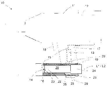
Figs. 1-5 show a setting tool according to the present invention which
is driven with liquid or gaseous fuel which forms the propellant, and is
equipped with a propellant container 20 according to the present invention.
The setting tool 10 has a housing 11 with a handle 16 formed thereon. On
the handle 16, there is provided an actuation switch 17 for initiating a
setting
process. The setting tool 10 further includes a setting mechanism having a
combustion chamber 28 for combusting an air-propellant mixture. The
propellant container 20 is replaceably received in a receptacle 16 according
to the present invention of the setting tool 10. In the embodiment shown in
the drawings and described here, the propellant container is formed as a gas
vessel. The propellant container 20 is inserted into the receptacle 16 through
an opening 19 of the receptacle 16. The propellant container 20 has, at one
of its ends, a valve outlet 23 of a valve 22 through which the propellant can
flow out of the propellant container receptacle 20. In the propellant
container receptacle 16, there is provided a closure element 14 such as, e.g.,
a closure union. The closure union 14 is connected with the valve outlet 23
when the propellant container 20 is completely inserted in the propellant
container receptacle 16, as shown in Figs. 1-2. Appropriate sealing means
9
CA 02567544 2013-11-22
such as, e.g., gaskets can insure the leak tightness of the socket connection.
The closure element 14 is connected by a propellant conduit 15 with a
metering device 13 that, e.g., includes a valve. The propellant conduit 15
further connects the metering device 13 with the combustion chamber 12. In
this way, propellant or fuel flows from the propellant container 20 through
the propellant conduit 15 and the metering device 13 in the combustion
chamber 12 of the setting tool 10.
For releasable securing the propellant container 20 in the propellant
container receptacle 16, three is provided at an end or end region 29 of the
propellant container 20 opposite the valve outlet 23, a connection element 24
having a locking member 25. The connection element 24 is formed as
closing means or a closing body for an opening 19 of the propellant
container receptacle 16. The locking member 25 is formed as a spring
shackle provided at one of its ends with a web 27 securable to the
connection element 24 and, at its other end, with a locking hook 28. On the
locking member 25, there is further arranged an actuation member 26, which
is manually actuated by the tool user for pivoting the locking hook 28 on the
spring shackle in a direction of the connection element 24. Preferably, the
connection element 24 is formed together with the locking member 25 and
CA 02567544 2013-11-22
the actuation member 26 as a one-piece part as a plastic injection-molded
part.
The locking member 25 of the propellant container 20 cooperates with
a counter-locking member 35 provided at an end region 39 of the propellant
container receptacle adjacent to the opening 19. The counter-locking means
35 has a first counter-locking element 36 and a second counter-locking
element 37 formed as locking openings. The locking hook 28 engages in
these locking openings for securing the propellant container 20 in the
propellant container receptacle 16 in two different locking positions.
In Figs. 1-2, the propellant container 20 is held in the propellant
container receptacle 16 in the second position in which the valve outlet is
connected with the connection element 14 or is inserted therein. In the
second position, the locking hook 28 of the locking member 25 engages the
second counter-locking element 37. In the second position, as it has already
been described, propellant is fed through the propellant conduit 15 and the
metering device 13 to the combustion chamber 12. The opening 19 is closed
with the connection element 24 formed as closing means or closing body, so
that no dirt can penetrate in the propellant container receptacle 16.
When the setting tool 10 need not be used for a long time, it makes
sense to disconnect the propellant container 20 from the metering device 13.
11
CA 02567544 2013-11-22
To this end, the propellant container 20 need not be completely disconnected
from the propellant container receptacle 16. Rather, by actuation of the
actuation member 26 and release of the locking hook 28 from the second
locking opening (the second counter-locking element 27), and a partial
withdrawal of the propellant container 20 from the container receptacle 16,
the propellant container 20 is displaced to a first locking position in which
the locking hook 28 engages the first counter-locking element. In the first
locking position, the valve outlet 23 is disconnected from connection
element 14 (please see Fig. 3). The actuation of operational member 26 of
the locking member 25 and withdrawal of the propellant container 20 can be
carried out with one hand. The valve outlet 23 is closed in this position with
the valve 22. In the first locking position, likewise, the opening 19 of the
propellant container receptacle 16 is closed by the connection element 24
which is formed as a closing body, and no dirt penetrates in the propellant
container receptacle 16. Thus, the propellant container 20 can be supported
on the setting tool 10 also in the first locking position.
In Fig. 4, the propellant container 20 is completely withdrawn from
the propellant container receptacle 16 after actuation of the operational
member 26 anew for disconnecting the locking hook 28 from the first
locking opening (the first counter-locking element 26). With the propellant
12
CA 02567544 2013-11-22
container 20 being withdrawn, a new propellant container can be received in
the propellant container receptacle 16.
As shown in Fig. 5, the propellant container 20 has means for securing
the propellant container 20 in the propellant container receptacle 16 without
possibility of rotation relative thereto. The securing means includes, in the
embodiment shown in the drawings, a first groove-shaped recess 41 and a
second groove-shaped recess 42 provided both on the connection element
24. The recesses 41, 42 extend in the direction of a longitudinal axis Li of
the propellant container 20 and have respectively, different widths (in a
direction transverse to their longitudinal extent). Thereby, an inadvertent
rotation of the propellant container 20 in the propellant container receptacle
16 is prevented, which, e.g., can take place upon removal of the propellant
container 20. By forming the groove-shaped recesses 41, 42 with different
width, simultaneously, there is produced a key profile that can characterize
the propellant contained in the propellant container 20.
Upon insertion of the propellant container 20 in the propellant
container receptacle 16, a first rib-shaped projection 44 and a second rib-
shaped projection 45 of the second means for securing the propellant
container 20 in the propellant container receptacle 16, which is provided in
the propellant container receptacle 16, penetrate into the groove-shaped
13
CA 02567544 2013-11-22
, .
recesses 41, 42, respectively. The rib-shaped projections 44, 45 extend in
the direction of a longitudinal axis L2 of the propellant container receptacle
16. The outer profile of the rib-shaped projections 44, 45 corresponds to the
inner profile of the groove-shaped recesses 41, 42 and for corresponding
closing profile. The key and closing profiles can define, along with securing
the propellant container 20 in the propellant container receptacle 16 without
a possibility of rotation relative thereto, which propellant containers 20 can
be used with the setting tool 10, in order to prevent use of a non-allowable
fuel that can damage the setting tool or result in an erroneous setting.
By aligning the groove-shaped recesses 41, 42, and the rib-shaped
projection in the directions of axes Li, L2, respectively, the propellant
container 20 is properly aligned in the propellant container receptacle 16, so
that tilting of the propellant container 20 in the propellant container
receptacle 16 is prevented.
Though the present invention was shown and described with
references to the preferred embodiment, such is merely illustrative of the
present invention and is not to be construed as a limitation thereof and
various modifications of the present invention will be apparent to those
skilled in the art. It is therefore not intended that the present invention be
limited to the disclosed embodiment or details thereof, and the present
14
CA 02567544 2013-11-22
invention includes all variations and/or alternative embodiments within the
scope of the present invention as defined by the appended claims.