Note : Les descriptions sont présentées dans la langue officielle dans laquelle elles ont été soumises.
CA 02567778 2006-11-22
WO 2005/116576 PCT/SE2005/000750
-1-
Measuring device and a method for measuring the thickness of a layer of a
moving strip
Technical field
The present invention relates to a measuring device and a method for
measuring the thickness of a layer of a moving strip according to the
preamble to Claims 1 and 5 respectively.
Background art
In the production of material in strips, such as paper or sheet-metal, which
runs over rollers, it is desirable to be able to measure the thickness of the
said strips or of a layer thereof, for example of paint or film, in order to
be
able to control the production in various respects.
To this end, it is known to use a type of measuring equipment in which a
transmitter, movably mounted in a transmitter housing, is kept at a certain
distance from a measured object by means of gas which is blown out
between the transmitter and the strip and forms a gas cushion between them.
With the aid of such a gas cushion, the gap between the transmitter and the
measured object can be kept small and constant, which is beneficial to the
measuring accuracy, without the transmitter hitting against the strip, which
might cause damage to both the strip and the measuring device. It is also
important for the measuring accuracy that the transmitter is easily movable
within the transmitter housing, which is normally fixedly mounted. This is
preferably achieved by gas-mounting of the transmitter in the transmitter
housing, whereby the position of the transmitter can be adjusted to the
particular thickness of the measured object.
A.measuring device according to the above is known, for example, from
Swedish patent SE 515 644.
CA 02567778 2006-11-22
WO 2005/116576 PCT/SE2005/000750
-2-
A thickness measurement of the strip or layer by means of a measuring
device according to the above suffers from a considerable drawback,
however, since the pressure exerted upon the strip by the gas cushion tends
to produce unwanted deformations of the said strip. Just such a deformed
strip 2 is shown in Figure 1, in which a portion 2a of the strip has been
pressed against a roller 3 in the position before a diagrammatically shown
measuring device 11. The result of these deformations is impaired accuracy
of the measurement results and false values for the thickness of the strip or
layer.
Object of the invention
The object of the present invention is to provide a measuring device which
produces minimal deformations of the object whose thickness is to be
measured.
Disclosure of invention
The object of the present invention is achieved by means of a measuring
device according to Claim 1 and a method according to Claim 5.
Claim 1 describes a measuring device for measuring the thickness of at least
one layer of a moving strip, comprising a transmitter body, which is axially
movable within a transmitter housing and has a sensor head, designed to rest
against the layer via a gas cushion, and an upper portion, extending into a
chamber delimited within the transmitter housing. The transmitter housing is
provided with at least one port for the supply of gas, which flows, in part,
through a longitudinal duct in the transmitter body so as to form the said gas
cushion and flows, in part, into the chamber. The measuring device is
characterized in that the transmitter housing is provided with a restrictor
for
evacuating gas from the chamber.
CA 02567778 2006-11-22
WO 2005/116576 PCT/SE2005/000750
-3-
By manoeuvring the restrictor, it is possible to regulate the gas pressure in
the chamber. Since the pressure in the chamber acts directly upon the upper
portion of the transmitter body, a regulation of the force exerted upon the
transmitter head in the direction of the strip is also thereby achieved and
the
gas pressure is expediently adjusted in such a way that the pressure required
in the gas cushion for separating the sensor head and the strip is minimized.
The minimization of the pressure exerted upon the strip by the gas cushion
solves the problem of strip deformations during measurement stemming
from this pressure, which produces truer measurement results.
It is advantageous if the restrictor is manually controllable, since it hereby
becomes possible to dispense with dear and complicated equipment for
controlling the said restrictor. This is especially the case where a single
adjustment of the restrictor prior to a thickness measurement is deemed
sufficient.
The measuring device advantageously comprises a pressure sensor for
determining the pressure in the gas cushion. Such a pressure sensor is
expediently placed in the chamber to measure the pressure therein, which
measurement values, through a known relationship, are used in determining
the pressure in the gas cushion.
In certain cases, it can also be advantageous if the measuring device
comprises at least one computer member for calculating the pressure acting
against the layer via the gas cushion, on the basis of the pressure in the
chamber determined by means of the pressure sensor, and for automatically
controlling the restrictor in dependence on the calculated pressure against
the
gas cushion, since a continuous control ensures that the pressure against the
strip is not varied over time.
CA 02567778 2006-11-22
WO 2005/116576 PCT/SE2005/000750
-4-
Claim 5 describes a method for measuring the thickness of at least one layer
of a moving strip, comprising the step of measuring the thickness of the layer
by means of a measuring device comprising a transmitter body, which is
axially movable within a transmitter housing and has a sensor head, designed
to rest against the layer via a gas cushion, and an upper portion, extending
into a chamber delimited within the transmitter housing. The transmitter
housing is provided with at least one port for the supply of gas, which flows,
in part, through a longitudinal duct in the transmitter body so as to form the
said gas cushion and flows, in part, into the chamber. The method is
characterized by the step that a restrictor, leading to the chamber, for
evacuating gas from the chamber is adjusted prior to a thickness
measurement of the layer in such a way that the gas cushion exerts a pressure
against the layer equivalent to a weight of 0-65 g/cm2. Deformations of the
strip according to the above are thereby eliminated and truer measurement
results are therefore acquired.
As has been mentioned above, it is advantageous if a computer member
automatically and continuously calculates the pressure acting against the
layer via the gas cushion, on the basis of a pressure in the chamber
determined by means of a pressure sensor, and controls the restrictor in
dependence on the calculated pressure against the layer in such a way that
the gas cushion continuously exerts a pressure against the layer equivalent to
a weight of about 0-65 g/cm2.
Brief description of drawings
The invention will now be described with reference to the appended figures,
in which:
Figure 1 shows how a strip is deformed in the use of a measuring device
according to the prior art;
CA 02567778 2006-11-22
WO 2005/116576 PCT/SE2005/000750
-5-
Figure 2 shows a diagrammatic cross section through a measuring device
according to a preferred embodiment of the present invention;
Figure 3 shows a diagrammatic cross section along the line A-A in Figure 2;
and
Figure 4 shows the air flow through the measuring device according to
Figure 2.
Mode(s) for carrying out the invention
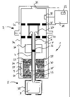
Figure 2 shows a measuring device 1 according to the invention, positioned
above a strip 2 of suitable material, such as paper or sheet-metal, for
measuring the thickness of the strip 2(alternatively the thickness of a layer
in the strip, such as a coat of paint on a sheet-metal base). The strip 2 is
supported by a support member 13, for example a roller in a production plant
for the said strip 2.
The measuring device 1 comprises a transmitter body 4, which is gas-
mounted in a transmitter housing 3 and is axially movable and has a sensor
head 5 projecting from the transmitter housing 3, which sensor head 5, in
turn, comprises a sensor 8 gas-mounted in a sensor housing 15. The sensor 8
is connected by a wiring arrangement 17 through the transmitter body 4 in a
known manner to a measuring system 18 for handling measurement signals
from the said sensor 8, and operates according to the reluctance principle or
in some other way (for a closer description of the reluctance principle, refer
to American patent US 4,387,339).
The transmitter housing 3 consists of two housing parts joined tightly
together, namely an upper housing part 3a and a lower housing part 3b,
which together delimit a chamber 7. The lower housing part 3b also delimits
an antechamber 14, in which a control part 19 is tightly accommodated,
through which control part 19 an upper portion 6 of the transmitter body 4
CA 02567778 2006-11-22
WO 2005/116576 PCT/SE2005/000750
-6-
runs in the form of a tubular shaft, from the sensor head 5 and into the
chamber 7. In the chamber 7 a fixing body 16 is mounted on the shaft 6,
which fixing body 16, above all, is intended in a known manner, by means of
rod-shaped control elements (not shown), to prevent rotation of the
transmitter body 6 relative to the transmitter housing 3 (for a closer
description of these control elements and their working, refer to Swedish
patent SE 515 644).
As can be seen from Figure 2, the control part 19 is provided with a central
vent 23 for the reception and gas-mounting of the shaft 6. From this vent 23,
a number of radial ducts 27 emerge into a space 26 between a shell surface
of the control part 19 and the lower housing part 3b, intended to conduct gas,
for example air, from the space 26, supplied via a port 9 in the lower housing
part 3b, to the vent 23. In the vent, the gas can then flow through openings
25 made in the shaft 6 to a duct 21 running through the shaft.
As can be seen from Figures 2 and 3, the shaft 6 is positioned in the vent 23
such that the openings 25 are situated in a portion thereof of larger
diameter,
forming an inner space 30 in the control part 19. The advantage with such an
arrangement is that the greater volume of the inner space 30 ensures good
pressure equalization therein, even when the measuring device 1 is tilted,
thereby producing a predictable, even flow of gas into the shaft 6. To the
same end, it is further advantageous if the openings 25 in the shaft 6 are not
positioned directly in front of the radial ducts 27, they can equally, for
example, be angled relative to the latter, as shown in Figure 3, thereby
ensuring a pressure equalization for the gas prior to flowing into the shaft
6.
Tightly accommodated in the duct 21 in the shaft 6 is a plug 32 for
preventing gas from flowing into the chamber 7 via the duct 21, which plug,
in a gas-tight manner, surrounds the wiring arrangement 17 running through
CA 02567778 2006-11-22
WO 2005/116576 PCT/SE2005/000750
-7-
it. In Fig. 2, the plug 32 is present within the fixing body 16, but it can
also
be fixed in other positions in the duct 21 above the openings 25.
Also present in the chamber 7 is an upper contact element 35, which is
mounted in the upper housing part 3a and can be coupled together with a
lower contact element 36, which is mounted in the lower housing part 3b and
is connected by the wiring arrangement 17 to the sensor 8. The upper
housing part 3a can thereby be removed from the lower housing part 3b,
upon requirement, without damage to the wiring arrangement 17. As can be
seen from Figure 2, both the upper and the lower contact element are
provided with vents for the through-flow of gas.
Finally, the transmitter housing 3 contains a restrictor 10, for example a
throttle valve, which is intended to conduct gas out from the chamber 7 to
the atmosphere surrounding the measuring device 1. The restrictor 10 in
Figure 2 is automatically controllable, in a manner to be described in further
detail below, by means of a computer member 12 belonging to the measuring
system 18, but might be manually controllable in another embodiment. In the
chamber 7 there is also mounted a pressure sensor 38, it, too, connected to
the computer member 12, for registering the pressure in the chamber 7.
Figure 4 shows, by means of unnumbered arrows, how the gas flows through
the measuring device 1. It is evident from this that the gas flows in through
the port 9 and, via the radial ducts 27, into the vent 23 in the centre of the
control part 19. Owing to the fact that the shaft 6 runs with a certain
clearance in the vent 23, the gas flowing into it produces an air-mounting of
the said shaft 6, which means that it is displaceable virtually without
friction.
The gas then flows either parallel along the shell surface of the shaft 6 and
into the chamber 7 or out from the measuring device 1, or through the
openings 25 and into the duct 21 in the shaft 6. When the duct 21 is filled
CA 02567778 2006-11-22
WO 2005/116576 PCT/SE2005/000750
-8-
with gas, which gas will eventually leave the duct 21 to form the gas cushion
between the sensor 8 and the strip 2, a pressure is generated against the plug
32 present in the duct 21 in the direction away from the strip 2. Simultaneous
to this, the gas flowing into the chamber 7 will press against the upper
portion 6 of the transmitter body 4 and the plug 32. In the absence of the
restrictor 10, or in the event of a total closure thereof, the pressure in the
chamber 7 will become somewhat higher than the pressure in the duct 21 in
the shaft 6, which, in combination with a somewhat larger pressure surface,
results in a force resultant acting in the direction of the strip 2 and
opposed
by the pressure in the gas cushion formed between the strip 2 and the
transmitter body 4. The effect is that the gas cushion also exerts a pressure
against the strip 2, usually equivalent to a weight of about 320 g/cm2, which
gives rise to the aforementioned strip deformations. If, on the other hand,
the
restrictor 10 is set by means of the computer member 12 to admit a certain
gas flow, then the pressure locally within the chamber 7 is lowered,
producing a reduction in the force resultant acting upon the transmitter body
(which force resultant may, in the extreme case, be negative). The effect is
that the pressure in the gas cushion, opposing the force resultant, is able to
be reduced, which stems from the fact that a part of the gas which previously
helped to form the gas cushion now flows out through the restrictor 10. The
result is a lowering of the pressure which the gas cushion exerts against the
strip 2 to a level equivalent to a weight of about 0-320 g/cm2, most
advantageously about 0-65 g/cmZ, at which no perceptible deformations of
the strip 2 occur.
The restrictor 10 is advantageously set to a suitable through-flow in advance
of the use of the measuring device 1, for example through measurement of
the pressure exerted against the strip 2 by the gas cushion. In certain
situations, however, it may also be desirable to conduct a regular check on
the pressure in the gas cushion to ensure a continuously high quality of the
CA 02567778 2006-11-22
WO 2005/116576 PCT/SE2005/000750
-9-
acquired measurement results. To this end, the pressure sensor 38 is mounted
in the chamber 7 for continuous measurement of the pressure therein. On the
basis of the measurement results acquired by means of the pressure sensor
38, the computer member 12 can then use a predetermined relationship
between the gas pressure in the chamber 7 and the gas cushion to calculate
the pressure exerted against the strip 2 by the gas cushion and can control
the
restrictor 10, on the basis thereof, to combat any pressure changes.
The invention is not, of course, limited to the embodiment described above
and expert modifications of the measuring device are possible without
thereby departing from the scope of the protection as defined by the
following independent claims. For example, the restrictor may be placed
elsewhere in the measuring device as long as it conducts gas away from the
chamber, and more or less than one pressure sensor may be present, either in
the chamber or elsewhere in the measuring device. If the restrictor is
controlled manually, it is also possible to dispense fully with the computer
member and the pressure sensor, in which case the restrictor is set just once
prior to measurement, for example by measuring, by means of a wave, a
pressure exerted against the latter by the gas cushion (alternatively the
pressure sensor can be read manually). Finally, in the above description it is
stated that the measuring device is placed above the strip, whereas, in an
alternative embodiment, it may be differently mounted, for example below or
beside the strip, as long as it extends essentially perpendicular thereto.