Note : Les descriptions sont présentées dans la langue officielle dans laquelle elles ont été soumises.
CA 02568191 2006-11-20
ICE REMOVAL APPARATUS
TEC'.HN1CA.L FIELU
t4oo1l This invention relates to an apparatus for snow and ice removal.
BACKGROUND
100021 Shoveling snow to keep sidewalks and driveways clear is a recurring
task that
keeps people busy for several months of the year in many parts of the world.
In regions where
temperatures rise during the day, causing some of the snow to melt, and then
quickly drop during
the night. treacherous ice can form. Water that pooled during the day from
melting snow can
refreeze into difficult to remove ice. Additionally, snow that is packed down,
for example on a
busy sidewalk, can also turn into hard ice that can be difficult to rernove
wit.h a conventional
snow shovel. Ice picks can be used to break up the ice and a shovel or
snowblower can then be
used to clear the broken ice out of the way. SUMMARY
[00+031 This invention relates to an apparatus configured for snow and ice
rernoval. In
general, in one aspec;t, the inveEjtian features an ice removal apparatus
including a scoop and at
least oneic.e breaE,er. The scoop is configured to scoop up snow and ice. The
at least one ice
breaker is connected to the scoop.
100041 Implementations of the invention can include at least one or more of
the following
features. The apparatus can further include a handle including a hand grip on
airst end and a connected to the scoop on a second end. The at least one ice
breaker can protrude from a leading
edge of the scoop, or in alternatively or additionally from a side edge of the
scocrp. The
apparatus can further include a pivotable connection. The at least one ice
break-er is connected
by the pivotable connection to the scoop and can be positioned in an extended
position to
perform ice breaking and can be pivoted to a retracted position to perform
snow and ice
shoveling. In one example, the pivotable connection is a hinge. The at least
one ice breaker can
include at least one tooth protruding from an edge of the scoop. The tooth can
include at least
one serrated edge. The at least one ice breaker can be a substantially
rectangular protrusion. The
substantially rectangular protrus:ioncatt include a serrated leading edge.
CA 02568191 2006-11-20
1""I Implementations of the invention can realize one or more of the following
advantages. A user of the ice removal apparatus can perform multiple tasks
with the single tool.
The tool en.n be used to simply shovel snow. However, if the user must also
break or loosen ice,
the ice breaker included on the apparatus can be eniployed to accomplish this
task. Once the task
of breaking and/or loowning the ice is completed, the user can then use the
scoop included on
the apparatus to clear away the iee. Because only one tool is required, the
user can easily toggle betu-een performing the two related but different
tasks. The user avoids having to carry more
than tine tool to a,job site and have one tool lay idle, with the risk of
misplacinl, the idle tool,
while ps;.rfomiing a~k with the other. The tool can conveniently be stowed in
the trunk of a
vehicle or on the wall of a shed or garage, and takes up less space than
having to store or
transport more than one toot.
[0006} 1'he details of one or more embodiments of the invention are set forth
in the
accompanying drawings and the description below. Other features, objects, and
advantages of
the invention wil1 be apparent from the descriptYon and drawings, and from the
claims.
DESCRIPTION OF IJRAWINGS
[0007] FI~'z. I shours an ice removal apparatus.
104081 FIG 2 shows an alternative embodiment of a scoop of the ice removal
apparatus
ofI~Ia I,
t(ttHl91 FIG 3 shows an alternative embodiment of a scoop of the ice removal
apparatus
of FICi. 1
100101 FICx 4 shows an alletnative embodiment of a scoop of the ice removal
apparatus
of FICi. 1.
100111 FICt 5 shows an alternative embodiment of a scoop of the ice rei-noval
apparatus
ofFIG. I.
100121 FIG 6 shows an alternat.ive embodiment of a scoop of the ice removal
apparatus
of FIG. I.10013] PICL 7A shows a cross-sectional view of the scoop shown in
FIG 5 along line ~~
with the ice breaker in an extended position.
(00141 FIG 78 shows a cross-sectional view of the scoop shown in FIG 5 along
line A-A
with the ice breaker in a retracted positian.
2
CA 02568191 2006-11-20
[0{Iv5j Like reference symbals in the various drawings indicate lilte
elements.
DETAILED DESCRIPTIOIV 100161 An ice removal apparatus is provided that
includes a scoop configured to scoop up snow and ice wW at least one ice
breaker. The scoop can be configured in asirnitar shape and size to a
conventional head of a s}wvel, snow shovel or spade. However, unlike a
ctmventional
shovel or space, an ice breaker is connected to the scoop.
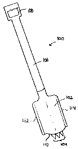
100171 Referring to FIG. 1, one embodiment of the ice removal apparatus 100 is
shown.
3I'he ice removal apparatus 100 includes a scoop 102 and an arrangement of ice
brealcers 104.
7lze sc:oop 102 includes two side edges 112, 114 and a leading edge 110. In
this ernbodiment, the ice breakers 104 are positioned along the leading edge
11 0 of the scoop and are configured as
substantially triangular shaped teeth. The ice breakers 104 can be used to
break up ice, for exatnpte, by direoing the ice breakers I04 at a patch of ice
and applying a downward force.
Applying the downward force in sharp, quick, jabbing motion can be effective
to break up ice.
The scoop 102 can then be used to scoop up the broken ice and any surrounding
snow, and
remove same from an area, for exarnple, a sidew=alk, path or driveway. [{}018]
In this embodiment, the ice removal apparatus 100 further includes a handle
106
and a hand grip 108. In operation, a user holds onto the ice removal apparatus
by the hwid grip 109 and optionally the handle 1(}6. As described above. when
using the ice removal apparatus
100 to break up ice, the user can direct the ice breakers 104 toward the ice
and apply a downward
force sufficient to break up the ice. The pointed configuration of the ice
breakers 104 facilitates
breaking the ice. Preferably the ice breakers 104 are formed from a tiard,
durable rnaterisl, such
as a metal, that can witbstand the fomes involved in breaking the ice. The
edges of the ice
breakers 104 can be substantially shaip and optionally serrated to further
facilitate ice breakage.
[00191 In other embodiments, the ice breakers 104 can be positioned
substantially toward
one side of the leading edge 110 rather than centered'. or can be positioned
on one or both of the
side edges 112, 114. For example, neferring to FIG. 2, another embodiment of
the scoop 202 is
showm. In this embodrrnent, the ice breakers 204 are positioned along a side
edge 214 of the scoop 202. Alternatively, the ice breakers 204 can be
pasitionedalong the other side edge 212.
Positioning the ice brealcers 204 along a side edge 212 or 214 can permit the
scoop 202 to
operate more easily when performing a scooping functiott, as compared to the
ice breaking
3
CA 02568191 2006-11-20
function, in that the ice breakers204 are positioned out of the way of the
leading edge 210 and
do not hinder a scooping or shoveling motion. [00201 The configuration of ice
breakers 104, and 204 shown in the embodiments
depicted in FIGS. I and 2 is exemplary. Other configurations can be used.
Referring to FIG. 3,
and altern.ative embodiment of the scoop 302 is shown. The ice breaker 304 is
configured as a
single, enlarged tooth protruding from the leading edge 30t's of the scoop
302. The leading edge
304 of the ice breaker 304 can be sharpened to provide a cutting action when
forced against ice.
Alternativel}r, the side edges 310, 312 of the ice breaker 304 can be
sharpened as well.
[0021} Referring to FIG. 4, an altemative embodiment of the scoop 402 is
shown,
wherein the ice breaker 404 is positioned along a side edge 406 of the scoop
402. As described
above, providing the ice breaker 404 along a side edge 406 can facilitate
using the scoop 402 for
a scooping or shoveling operation, as the ice brealcer 404 is out of the way
of the leading edge
408 that perforrn.s most of the scooping in a shoveling operation.
[0022] Referring now to FIG, 5, an altemative embodiment of a scoop 502 is
shown. In
this ernlacxliment, an ice breaker 504 is positioned along a leading edge 506
of the scoop 502.
'I'he ice breaker 504 is configured as a single toatli including at least one
serrated edge. In the
embodiment shown, the serrated edge is the leading, edge 50$ of the ice
breaker 504.
Alternatively or additionally, one or both of the side edges 510 and 512 of
the ice breaker 504
can be serrated.
[(1{}231 Referring to FIG. t, an alternative embodiment of a scoop 602 is
shown. In this
embodiment, the ice breaker 604 is positioned along a side edge 606 of the
scoop 602. The ice
breaker 604 is conYigured as a single tooth and includes a serrated leading
edge 608.
Alterraativeiy or additionally, the side edges 61 {l and 612 of the ice
breaker 604 can be serrated.
[0024] In an alternative embodiment, the ice breaker can be pivotally attached
to the
scoop, such that the ice breaker can pivot between an extended and a retracted
position. In an
extended position, the ice breaker protrudes from the scoop and can be used to
break ice. In a
retracted position, the ice breaker is folded out of the way of the scoop, so
as not to interfere with
tlte scooping or shoveling operatictn,Referring to FIGS. 7A and 7B, a cross-
sectional view of
the scoop 502 shown in FIG. 5 is show-ii taken along line A-A. In this
embodiment of the scoop
502, the ice breaker 504 is pivotally attached to the leading edge of the
scoop 502, for example,
wing a hinge 514 or other connection allowing a pivoting motion between the
ice breaker 504
4
CA 02568191 2006-11-20
and scoop 502. The ice breaker 504 can pivot about the hinge 514 in the
direction of arrow 516
to switch between an extended position slwwn in FIG. 7A and a retracted
position shown in FIG.
7B. In FIG. 7A, the ice breaker 504 is locked into an extended position and
can be used to break
up ice. In FIG. 7B, The ice breaker 504 has been pivoted into the retracted
position and is tucked
underneath the scoop .502 and out of the way of the leading edge 506 of the
scoop 502.
100251 In another embodiment, an ice breaker that is connected to a side edge
of the scoop, for example, the ice breaker 604 shown in FIG. 6, can be
pivotally attached to the scoop 60:2. The ice breaker 604 can thereby be
retracted out of the way of the scoop 602 when the user
is not using the ice breaking function of the ice removal apparatus. i00261 In
one embodiment, the scoop and at least one ice breaker are formed from a hard,
durable material such as a metal or plastic. The handle and hand
gripcanbeformed from any suitable rnaterial including wovd, plastic or meul,
or a combination thereof In one implementation the scoop and at least one ice
breaker are formed as an integral unit. For example, if formed from metal, the
scoop and ice breaker can be extruded as a single unit, or if formed from
plastic they can be molded or extruded as a single unit. In one
implementation, the
hand grip and handle are formed as an integral. unit. In yet
anotheritnplernentation, the handle,
scoop and at least one ice breaker are aII formed as an integral unit. In
other implementations,
the components are formed separately and connected together. For example, the
scoop can be
screwed or otherwise mechaWcally fixed to the handle. In another example, the
at least one ice
breaker can be fused to thes coop, for exannpl+e, by welding, adhesive or
thermal bonding.
100271 A nurnber of embtxdiments of the invention have been described.
Nevertheless, it
wilt be understood that v ar'sous m ditications may be made without departing
from the spirit and
scope of the invention. Accordingly, other embodiments are within the scope of
the following
claims. ~