Note : Les descriptions sont présentées dans la langue officielle dans laquelle elles ont été soumises.
CA 02569281 2006-12-04
WO 2006/115998 PCT/US2006/014926
SYSTEM AND METHOD FOR MONITORING
PERFORMANCE OF A SPRAYING DEVICE
FIELD OF THE INVENTION
[0001] The invention concerns spraying devices such as nozzles, and more
particularly to a
system and method for monitoring the performance of a spraying device.
BACKGROUND OF THE INVENTION
[0002] Spraying devices such as nozzles are widely used in a variety of
industrial applications.
In many applications, the proper performance of spraying devices is critical
to the processing in
which the sprays are used. The failure of a spraying device may result in
defective products and
cause potentially significant economic.losses.
[0003] For instance, in the steel industry, spray nozzles of an internal-
mixing type are used for
steel cooling in a continuous casting process. An internal-mixing nozzle used
in such a casting
application provides a spray of a mixture a water and air, i.e., a mist. To
that end, the spray nozzle
has an internal mixing chamber, and water and air inlets with calibrated
orifices. Water and air are
fed through the inlet orifices into the internal mixing chamber, where they
axe mixed. The mixture
is transported through a tube to a nozzle aperture that discharges the'
mixture in a desired spray
pattern, such as a flat pattern. The spray generated by the nozzle is a
function of the input water
and air pressures, which may be set at different values for different
applications depending on the
particular requirements of the applications. For the nozzle to function
properly, the input air and
pressures have to be tightly controlled. Doing so, however, is not sufficient
to guarantee the proper
operation of the nozzle, because the air and water inlet orifices and the
nozzle tip may become
worn due to use or clogged, thereby preventing the nozzle from generating the
desired spray
output. Such performance degradation or malfunction of the internal-mixing
spray nozzles can
develop gradually overtime and has been difficult to monitor or detect.
SUMMARY OF THE INVENTION
[000] In view of the foregoing, it is an object of the invention to provide a
reliable way to
effectively monitor the performance of a spraying device, especially an
internal-mixing spray
nozzle, to ensure that it is functioning properly over the course of usage.
[0005] It is a related object to detect any significant performance
degradation or malfunction
of a spraying device, such as an internal-mixing spray nozzle, so that
spraying device can be
repaired or replaced promptly to minimize any potential economic losses.
[0006] These objects are effectively addressed by the system and method of the
invention for
monitoring the performance of a spraying device. The spraying device has at
least a first inlet for
CA 02569281 2006-12-04
WO 2006/115998 PCT/US2006/014926
2
receiving a first fluid and a second inlet for receiving a second fluid. The
spraying device further
includes an internal mixing chamber whether the first and second fluids are
mixed. The mixture is
transported from the mixing chamber to a nozzle aperture, which discharges the
mixture to form
a spray.
[0007] In accordance with the invention, a mixture pressure sensor is disposed
on the spraying
device downstream of the mixing chamber to detect the pressure of the mixture.
The input
pressures of the first and second fluids entering the spraying device are also
measured. The
measured pressures of the first and second fluids are used to calculate a
predicted mixture pressure
based on an empirical formula. The calculated value and the measured value of
the mixture
pressure are then used in a comparison process to determine whether or not the
spraying device is
functioning properly.
[000] Additional features and advantages are explained in more detail below
with the aid of
preferred embodiments shown in the drawings, of which:
BRIEF DESCRIPTION OF THE DRAWINGS
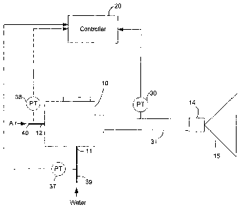
[0009] FIGURE 1 is a schematic view of an embodiment of a spraying system in
which the
performance of an internal-mixing spraying device is monitored by a
controller;
[0010] FIG. 2 is a cross-sectional top view of the spraying device in FIG. 1;
[0011] FIG. 3 is a cross-sectional side view of the spraying device with a
mixture pressure
sensor mounted thereon; and
[0012] FIG. 4 is a flowchart showing a process of setting up and operating the
system for
monitoring the performance of the spraying device.
DETAILED DESCRIPTION OF THE EMBODIMENTS
[0013] The present invention provides a system and method for monitoring the
performance
of a spraying device that receives different fluids and generates a spray of a
mixture of the fluids in
a given spray pattern. FIG. 1 shows an embodiment of such a spraying system,
which includes a
spraying device 10 and a controller 20 that monitors the performance of the
spraying device in a
way that will be described in greater detail below.
[0014] The spraying device 10 as shown in FIG. 1 has a first inlet 11 for a
first fluid to enter the
spraying device, and a second inlet 12 for a second fluid to enter the device.
The two fluids are
formed into a mixture inside the spraying device, and the mixture is ejected
from an output nozzle
end 14 of the spraying device in the form of a spray 15 with a desired spray
pattern. The spraying
device 10 may be used, for example, in a metal casting operation for providing
cooling to the cast
CA 02569281 2006-12-04
WO 2006/115998 PCT/US2006/014926
product, and in such an application the first and second fluids may be water
and air, respectively.
Even though the spraying device of the illustrated embodiment has two fluid
inlets, it will be
appreciated that more inlets can be added for applications where additional
types of fluids are to be
included in the mixture, and that the invention may be used to monitor the
operation of a spraying
device with three or more fluid inlets.
[0015] Referring to FIG. 2, the inlets 11, 12 are provided with fittings or
connectors 17, 18 to
receive pipes carrying the fluids. Inside the spraying device 10 is a mixing
chamber 22. The first
inlet 11 is in fluid communication with the mixing chamber 22 via a first
orifice 23, and similarly
the second inlet 12 is connected to the mixing chamber 22 via a second orifice
24. The first and
second orifices are used to meter the flow of the fluids into the mixing
chamber and preferably are
calibrated so that the relationship between the flow rate of each fluid into
the spraying device and
the fluid pressure is well understood. The first and second fluids entering
the inlets 1 l, 12 flow
through the respective orifices 23, 24 and are merged in the mixing chamber
22, where they form
a mixture, and the ratio of the fluids in the mixture is determined by the
flow rates of the fluids into
the nozzle. The mixture is carried by a tube 31 from the mixing chamber 22 to
the nozzle end 14,
where the mixture is discharged through a nozzle aperture 32 to form the
spray.
[0016] In accordance with a feature of the invention, a pressure sensor 30 for
sensing the
pressure of the mixture formed in the spraying device 10 is disposed directly
on the spraying device
to allow accurate measurements of the pressure. To that end, in the embodiment
shown in FIG.
2, a port 34 is provided on the tube 31 connecting the mixing chamber to the
nozzle aperture. The
port 34 is configured to receive the pressure sensor 30, as shown in FIG. 3.
Alternatively, the
pressure sensor 30 may be mounted on the body of the spraying device 10 such
that the pressure
sensor is in direct fluid communication with the mixing chamber 22. The
pressure sensor 30 is
selected to be able to withstand the pressure of the mixture in the spraying
device and to have a
sufficient sensitivity to enable accurate readings of the mixture pressure. A
suitable pressure
sensor may be, for example, the Model OT-1 pressure transmitter made by WIKA
Alexander
Wiegand GmbH & Co. I~G in I~lingenberg, Germany.
[0017] Returning to FIG. 1, to provide readings of the pressures of the first
and second fluids
flowing into the spraying device 10, pressure sensors 37, 38 are provided in
the pipe lines 39, 40
feeding the fluids to the spraying device 10. The pressure sensors 37, 3g
preferably are located
close to the inlets 11, 12 so their readings reflect accurately the pressure
values of the fluids
entering the spraying device. The three pressure sensors 37, 3~, 30 are
connected to the controller
such that the controller receives output signals of the pressure sensors,
which represent the
measured pressures of the first and second fluids and the mixture in the
spraying device,
respectively.
CA 02569281 2006-12-04
WO 2006/115998 PCT/US2006/014926
4
[0018] In accordance with a feature of the invention, the performance of the
spraying device
is monitored by the controller 20 by comparing the measured actual pressure
value of the
mixture with a predicted mixture pressure, which is calculated using the
measured pressures of the
fluids as inputs. The predicted mixture pressure is calculated using an
empirical formula that
describes the relationship between the expected mixture pressure and the input
pressures of the
fluids. The exact form or shape of the formula can be determinedlselected
based on an
understanding of the fluid dynamics involved and by finding a best fit of
measured data with the
formula.
[0019] By way of example, in one embodiment, the following formula with
several linear
parameters is used to predict the mixture pressure:
_ 7~ ~r x 7~ D x
Pmix r ~1 + ~2 ~ rain + U3 'Pwater + ~4 ~ rain 'l water (Equation 1)
In this formula, Pa;r is the measured pressure for the air, Pwater is the
measured pressure for the
water, and Pm;X is the predicted pressure of the mixture in the spraying
device. This formula
contains four linear parameters b1, b2, b3, and b4, which are to be determined
empirically. The
exponent x is a fixed number, such as 0.5. It has been found that this formula
provides a
reasonably good model for predicting the mixture pressure based on given input
fluid pressures. It
will be appreciated, however, that this formula is only one of different forms
of equations that may
be used, and the invention is not limited to the particular form of this
formula. Also, although the
use of a linear formula has the advantage of computational efficiency, non-
linear equations may
also be used to model the mixing behavior of the spraying device if such a
formula can more
accurately predict the mixture pressure and if the controller has sufficient
computational power to
carry out calculations involved in handling the non-linear equations.
[0020] In accordance with an aspect of the invention, the parameters in the
formula in
Equation 1 for calculating the mixture pressure can be learned by the
controller 20 when the
spraying device is "on-line," i.e., installed in its intended operating
position. In the learning
process, the input pressures of the fluids are varied, and the measured values
of the pressures of the
first and second fluids and the mixture are used as inputs for determining the
parameters. This
learning operation is preferably performed When the spraying device is first
put in service, under
the assumption that the nozzle is performing correctly as designed during this
phase. Once the
parameters of the formula for predicting the mixture pressure are determined
in this learning phase,
they can be used by the controller 20 in the subsequent operations of the
spraying device to
calculate the expected mixture pressure based on measured input pressures of
the fluids. The
expected mixture pressure value can then be used with the measured actual
mixture pressure in a
comparison process to determine whether the spraying device is operating
properly.
CA 02569281 2006-12-04
WO 2006/115998 PCT/US2006/014926
[0021] In one embodiment, the learning of the parameters of the empirical
formula is done via
a recursive least square parameter estimation algorithm, as set forth in the
following equations:
~'(f~' - il~~~t~~3(~_1)
~~~ _ ~~~~t9
~~~~ _ ~"(f~ _
~.+~r(~~~~(-l~~r'[~~ ,
where y(t) = measured mixture pressure at the moment t;
y(t) = prediction of measured mixture pressure at the moment t based on
information
before the moment t;
P(t) = inverse covariance matrix;
~I'(t) = input values (input measurements, air and water pressure)
8(t) = parameter vector (b1, b2, b3, b4)
~,(t) = forgetting factor (=1)
[0022] After the parameters in the mixture pressure formula are determined
using the recursive
least square algorithm, the formula is ready to be used by the controller 20
for monitoring the
performance of the spraying device. When the controller 20 detects a
significant deviation of the
measured mixture pressure in the spraying device from the predicted or
expected mixture pressure
and if the deviation lasts for a sufficiently long time, it generates a fault
signal to get the attention
of the operator of the processing line so that the possible cause of the
deviation can be investigated,
and the spraying device may be repaired or replaced if necessary.
[0023] In one embodiment, a combination of static and dynamic techniques is
used to
determine if a fault signal should be generated. In this fault determination
process, measurements
are taken periodically at regular intervals. For each measurement interval, a
static error state S; at
a certain moment in time (t;) is calculated as follows:
Pmmi: measured mixed pressure at time i
Pubs: maximum absolute error
Efel: maximum relative error (in %)
Absolute fault: Perr; = P"~;x; - P,~""~
CA 02569281 2006-12-04
WO 2006/115998 PCT/US2006/014926
6
Relative fault 1: Prlf - mix; ~ ~rel
Relative fault 2: ,r'r2 -- pmm ~ Ere!
i r
The error state at time t; is: S; _ (~ Pen. ; ~? Pabs ) ~' ~~ Perr; ~~ Prl; )
'~' (~ Pen; ~~ Pr2; ) '
[0024j Thus, the static error state S; is determined based on three threshold
levels: a
pre-selected fixed level Pa6s, and two variable levels Pr;; and Pr2; that
depend on the values of the
measured input liquid pressures. The values of Pays and Ere; are chosen
depending on the accuracy
of the sensors and the stability of the signals. A good choice for Pans is,
far example, 3 times the
standard deviation on Pen, measured on a large number of points (e.g. 1040) in
the normal
operating range of the nozzle. In that case, the Pubs is calculated based on
the following equations:
;~ ~ C _
Perr;
~'abs
t=o
i=n-1 P
err;
=o n
[0025] The type of error causing fihe pressure deviation depends on the sign
of Pe~.. If the sign
is positive, the measured actual pressure is lower than the predicted
pressure. This may happen if
either the calibrated orifices are blocked or the tip is worn out. On the
other hand, if the sign is
negative, the measured pressure is higher than the predicted pressure, which
may occur if either the
calibrated orifices are worn out or the tip is blocked. Thus, based on the
sign of Pen, the possible
cause of the pressure deviation can be determined.
[0026] The dynamic error state (D;) is then calculated using the following
algorithm:
If sign(Pe,~;)~Sign(Pe,~;_,), then D; is false (valid situation).
If S; is false for at least Tgood, then D; is false (valid situation}.
If S; is true for at least Tbaa, then D; is true (fault detected).
In this determination, D; is set to be true only when the static error state
S; has been true for a
pre-selected time period Tbaa. This is done to reduce the likelihood that the
measured pressure
deviation is caused by noise or fluctuation in the liquid pressures or the
sensed pressure signals. If
the dynamic error state D; is true, the controller 20 determines that a fault
situation is found, and
generates a fault signal to indicate that the spraying device is not
functioning properly.
[0027] The following factors using in the decisions above have to be chosen,
and are
depending on the dynamics of the system:
Tgood : time needed with good samples before the situation is evaluated as
valid
Tbad : time needed with bad samples before the situation is evaluated as
faulty
CA 02569281 2006-12-04
WO 2006/115998 PCT/US2006/014926
7
[0028] The process of setting up the spraying device 10 and the controller 20
and the
subsequent monitoring operation are summarized in the flowchart in FIG. 4.
First, the spraying
device is set up in its intended operating position (step 40). A learning
process is then performed
under the control of the controller to determine the parameters in the
empirical formula to be used
for predicting the mixture pressure (step 41 ). Thereafter, during the normal
operations of the
spraying device, the controller continuously monitors the performance. For
each detection cycle,
the controller receives measured pressure signals for the input liquids and
the mixture from the
pressure sensors (step 42). The controller uses the measured input liquid
pressures as inputs for the
empirical formula to calculate the predicted mixture pressure (step 43). A
static error state S; for
the detection cycle is determined based on the measured and calculated
pressure values (step 44).
A dynamic error state D; is then calculated based on the present and past
values of the static error
state variable (step 45). If the dynamic error state D; is true (step 46), the
controller generates a
fault signal indicating that the spraying device is not functioning properly
(step 47).
[0029] In view of the many possible embodiments to which the principles of
this invention
may be applied, it should be recognized that the embodiments described herein
with respect to the
drawing figures are meant to be illustrative only and should not be taken as
limiting the scope of
the invention. Therefore, the invention as described herein contemplates all
such embodiments as
may come within the scope of the following claims and equivalents thereof.