Note : Les descriptions sont présentées dans la langue officielle dans laquelle elles ont été soumises.
CA 02570967 2010-07-05
AN ILLUMINATING DEVICE AND ASSEMBLY FOR ILLUMINATING ENCLOSED
SPACES USING THE SAME
RELATED APPLICATIONS
The present patent application relates to the issued US patent
7,722,237 issued on May 25, 2010.
FIELD of THE INVENTION
This invention -relates to illuminating devices, and more
particularly to the illuminating device and assembly for
illuminating enclosed spaces while highlighting a mark,
advertisement, insignia or the like.
BACKGROUND OF THE INVENTION
Numerous attempts have been made to design various devices
having a light source and switch assembly for illuminating
enclosed spaces, for example, for illuminating the rear
compartment of a motor vehicle upon opening movement of the
Compartment lid, a reading material for reading in bed, or a
toilet seat at night upon lifting the toilet seat cover.
Examples of such devices are described below.
US Patent No. 5,477,428 (Brown) issued December 19, 1995,
pertains to a lamp assembly to be mounted to the underside of
the hood of a vehicle hood or trunk lid to illuminate a
compartment of the vehicle when the hood or trunk lid is raised.
The device uses a gravity-actuated switch to make turning the
lamp on/off fully automatic.
CA 02570967 2006-12-11
CC-001-CA
US Patent No. 4,316,239 (Cass) issued February 16, 1982
discloses a lamp assembly to be mounted on the trunk lid, which
includes the gravity-actuated switch for automatically
illuminating the trunk when the trunk lid is elevated.
US Patent No. 3,692,992 (Bain) issued September 19, 1972 strives
to provide a universal solution for the problem of automatic
illumination of any kind of enclosure. It provides a lamp and
switch assembly for illuminating an enclosure having an opening
closable by a movable member pivotable between an open position
and closed position. The preferred embodiment addresses the
needs of motor vehicle operators, providing an illumination
solution for a rear compartment of the vehicle-
US Patent No. 2,206,094 (Hobbs) issued July 2, 1940 provides a
lamp and a gravity-actuated switch assembly for illuminating a
compartment when a closure member is opened, and turn off the
source of illumination when the closure member is moved to a
closed position. Its preferred embodiment relates to the engine
compartment of a vehicle.
US Patent No. 2,336,677 (Frey) issued December 14, 1943
addresses automatic illumination of a reading material for
reading in bed. It describes a lamp and gravity-actuated switch
assembly, normally concealed behind the headboard, for
illuminating a book when the lamp is in visible position, and
for turning off the source of illumination when the lamp is
moved to a concealed position.
US Patent No. 5,664,867 (Martin) issued September 09, 1997
provides a desion for automatic illumination of a toilet seat at
2
CA 02570967 2006-12-11
CC-001-CA
night. A nightlight is provided that is responsive to movement
so that when the toilet seat is lifted up, the light turns on,
and when the seat is lowered, the light turns off. The light is
turned on/off automatically by means of a tilt-sensitive switch.
US patent No. 6,851,820 (Choi) issued February 08, 2005
describes a light for a barbecue grill, which has a housing
mounted to the lid of the barbecue grill, a light source, power
source, a controller and a switch. The switch manipulates
illumination of the light source when the lid of the barbecue
grill is lifted.
US Patent No. 6,762,734 (Blotky) issued July 13, 2004 proposes
to use the outside surface of various types of containers for
displaying images related to the content of the containers. The
intent is to turn the containers into advertising vehicles for
the product inside of the container. The implementation
concentrates on using beverage cans as containers, and light
emitting polymer films (LEPF) as a medium for illuminating the
surface and displaying images onto. The electronic circuitry is
rather sophisticated and includes a microprocessor and various
sensors for detecting the opening of the container by a user-
Opening of the container is used as a signal to start surface
illumination, displaying images and providing other advertising
activities, e.g. sound etc.
In spite of the numerous attempts to design various devices for
illuminating enclosed spaces, the need still exists for a
simple, cost effective and easy-to-manufacture device for
illuminating enclosed spaces, the device having additional
functionality or utility e.g. carrying information or displaying
3
CA 02570967 2006-12-11
CC-001-CA
an insignia, and preferably utilizing a self-contained low
energy power source.
SLT RY OF THE INVENTION
In accordance with one aspect of the invention, there is
provided an illuminating device comprising:
a shell having two surfaces, a periphery and a first
translucent portion to be illuminated, and a light source
disposed for emitting light into the shell for propagating
between the surfaces by internal reflection, the shell
comprising a waveguide for propagating a part of light emitted
by the light source towards the first translucent portion of the
shell, and for propagating a part of light emitted by the light
source to a range of space outside the shell. The waveguide may
extend from the light source to the first portion of the shell.
In an embodiment of the invention, the waveguide extends from
the light source to the periphery of the shell.
In the embodiment of the invention, an advertisement, insignia,
symbol, graphics, logo or mark, hereinafter termed "insignia",
may be disposed on the first portion of the surface, the
insignia etc. to be illuminated by the light propagating through
the waveguide. The insignia may be attached, releasably or
permanently, to one of the surfaces of the shell or embedded in
the shell.
in the embodiment of the invention, the light source is disposed
so as to face a side face of the shell such that light energy
emitted by the light source is coupled into the shell between
the two surfaces, thereby defining a planar waveguide.
4
CA 02570967 2006-12-11
CC-001-CA
In the embodiment of the invention, the illuminating device
comprises a light scattering element, which is optically coupled
with the waveguide for distributing light to the outside of the
shell. The scattering element may be disposed along the
periphery of the shell. Alternatively, the scattering element
may be embedded in the waveguide. The scattering element may be
selected from the following: a diffraction grating, glass
spheres, plastic spheres, prisms, lenses or disturbances in the
surface of the shell.
The light source may be a light emitting diode. Preferably, it
is embedded in the shell so that light emitted by the diode is
coupled into the waveguide.
Advantageously, the waveguide is formed by the material and the
surfaces of the shell.
The device may further comprise a position sensitive switch for
turning the light source on or off depending on a spatial
orientation of the switch.
In accordance with another aspect of the invention, there is
provided an illuminating device which comprises:
a substantially translucent shell having a first and a
second end,
a light source disposed at said first end so that light
emitted by the source propagates down the shell and towards said
second end, and
a scattering element disposed at said second end for
receiving the light propagating towards said second end and
scattering the received light into a spatial angle outside the
shell near the second and of the shell-
5
CA 02570967 2006-12-11
CC-001-CA
In accordance with still another aspect of the invention, there
is provided an assembly, comprising:
the illuminating device as defined above, and a container
having a movable lid and an enclosed space to be illuminated,
wherein the illuminating device is mounted on the movable lid of
the container, the illuminating device including a circuitry for
turning the light source "ON" when the movable lid is in an open
position, thus simultaneously illuminating the enclosed space of
the container and the shell of the illuminating device.
In the embodiment of the invention, the circuitry comprises a
tilt switch for activating the light source depending on a
spatial position of the switch. The light source may be at least
one light emitting diode or it may be selected from one of the
following: a light emitting diode, a color-changing diode, a
small format incandescent light, organic light, cold-cathode
fluorescent light, electro-luminescent light, a laser, a laser
diode or a phosphor light.
Thus, the illuminating device of the embodiment of the
invention, when mounted on the lid, provides a dual
functionality of simultaneously illuminating the enclosed space
of the container and the shell of the illuminating device.
BRIEF DESCRIPTION OF THE DRAWINGS
The embodiment of the invention will now be described, by way of
example, with reference to the accompanying drawings in which:
FIGURE 1A is an isometric view of the illuminating device
according to the embodiment of the invention,
6
CA 02570967 2006-12-11
CC-001-CA
FIGURE 1B shows an exploded view of the illuminating device of
FIGURE 1A,
FIGURE 1C shows a side view of the illuminating device of FIGURE
1A,
FIGURE 2 illustrates a circuitry for use in the illuminating
device of FIGURE 1A,
FIGURE 3 illustrates an assembly of the illuminating device and
a container whose enclosed space is to be illuminated,
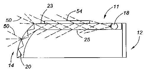
FIGURE 4 shows a light ray diagram for light emitting diode
embedded into the shell of the illuminating device of Figure 1A,
FIGURE 5A is a perspective view of the illuminating device
according to another embodiment of the invention,
Figure 5B is a top view of the illuminating device of Figure 5A,
and
Figure 5C is a cross-sectional view along the line A-A of Figure
5B.
DETAILED DESCRIPTION OF EMSODZMENTS OF THE INVENTION
As illustrated in Figs. 1A - 7.C, the illuminating device 10 has
a substantially translucent shell 11, having a first end 12 and
a second end 14. The device further includes a printed circuit
board (PCB) 16 mounted at the first end 12, including a light
source 18 comprising one or more light emitting diodes (LEDs)
18, batteries 34 and a required circuitry to operate the LEDs,
described hereinbelow. The LEDs 18 are disposed at the first end
12 so as to make the Licht emitted by LEDs 18 to prnpAgai down
7
CA 02570967 2006-12-11
CC-001-CA
the shell 11 and towards the second end 14 between an outer
surface 23 and inner surface 25 of the shell 11.
A light scattering element 20, e.g. in the form of shell surface
disturbances, plastic spheres, glass spheres or a diffraction
grating etc. is disposed at the second end 14 for receiving the
light propagated towards the second end 14 from the first end 12
and scattering (dispersing) the received light into a spatial
angle outside of the shell 11. For the purposes of embodiments
of the invention, the spatial angle is preferably smaller than 21t
steradians.
Thus, the shell 11 of the illuminating device 10 acts as a light
pipe or waveguide for transmitting light from the LEDs 18 to the
second end 14 of the illuminating device 10. The shell 11 can be
conveniently made of a translucent plastic such as polypropylene
or polystyrene, or any other substantially translucent and
preferably light material of similar physical properties. The
shell does not have to be entirely translucent, but it should
have at least a first translucent region for placing therein an
insignia or advertising material to be illuminated. The insignia
or advertising material may be disposed on or make part of the
shell 11 of the illuminating device 10, e.g. it may be disposed,
fixedly or preferably releasably, on an outer 23 or inner 25
surface of the shell 11, or it can be embedded in the shell 11.
Thus, when LEDs 18 are in operation, the advertising material is
illuminated with the light propagating down the shell 11 between
its outer and inner surfaces, thereby the material of the shell
and its surfaces forming a "leaky" light waveguide.
8
CA 02570967 2006-12-11
CC-001-CA
The thickness of the shell, if made of plastic, is preferably
within the range from about 0.5mm to about 6mm. In the
embodiment described herein, the thickness of the shell was
about 3 mm (0.12 in), i.e. comparable with the diameter of a
conventional LED.
Alternative light sources may be employed instead of, or
additionally to, LEDs, for example, incandescent (small format)
light, organic, cold-cathode fluorescent, laser, phosphor light,
electro-luminescent light and other conventional light sources.
Figure 2 shows a circuitry 30 mounted on the PCB 16 for
operating the illuminating device of Figures IA-1C. It includes
a tilt switch 32, resistors 33, 35 and 37, a battery 34 (which
is conveniently stored in the casing 22 of the shell 11 of the
illuminating device 10 as shown in Figure 1C), a LED 36, a
capacitor 38 and a transistor 40. The resistor 37 limits current
through the LED 36. The transistor 40 controls current flow
through the LED 36. The capacitor 38 combined with resistor 35
determines how long the transistor 40 stays on after the tilt
switch 32 closes. Once the capacitor 38 is fully charged, the
transistor 40 shuts off as resistor 35 pulls the gate to ground.
When the tilt switch opens, as will happen in a scenario
illustrated in Figure 3, the capacitor 38 discharges through
resistors 33 and 35. An optional diode 42 is provided to offer a
faster discharge path for capacitor 38.
It is conceivable, alternatively, to connect resistor 37
directly to the battery so that the resistor receives power all
the time, and connect the tilt switch only to resistor 33 and
capacitor 38. This modification offers the advantage or pa Ri nor
9
CA 02570967 2006-12-11
CC-001-CA
a relatively low current through the tilt switch 32. It is also
conceivable to install, if so desired, a manual switch (not
illustrated) beside the tilt switch.
Figure 3 illustrates an assembly 45 of the illuminating device
of the embodiment of the invention and a container to be
illuminated. The illuminating device 10 is mounted (e.g. by
means of Velcro(D or other conventional means) on the lid 46 of a
container 48, so that the light emitted by the LEDs) 18 exits
at the bottom of the device 10 as indicated by the arrows 50.
While a typical LED has a narrow divergence angle of a light
beam, in the range of a few degrees, the light beam becomes
expanded to a degree as it travels inside the shell 11 and
further dispersed as it exits through the light scattering
element 20 at the second end 14 of the shell 11. Preferably, in
order to better use the light energy available, the light
scattering element 20 should be selected so that the space
illuminated by the light rays 50 is limited to preferably not
more than Zit steradian in order to direct most of the light
towards the enclosure 52.
Figure 4 serves to illustrate the light guiding mechanism used
in the embodiment of the invention. As described earlier, the
plastic shell 11 is used as a light pipe, or more specifically,
a planar waveguide, for propagating light between the outer 23
and inner 25 surfaces of the shell 11 by internal reflection
(more specifically, by frustrated total internal reflection),
where a part of light is propagating down the shell 1.1 toward
the second end 14, and a part of light is leaving the waveguide,
thus illuminating the outer 23 and inner 25 surfaces of the
shell 11.
CA 02570967 2006-12-11
CC-001-CA
Thus, the light is conducted from the light source 18 down the
shell 11, being at least partly contained inside the shell 11,
to illuminate, by scattering, the first translucent portion of
the shell (exemplified by a region 13 in Figure 1A) and any
insignia or graphics or advertising material 54 that could be
disposed in the region 13. The scattering of light, at least in
the first translucent region 13, is virtually inevitable when
the shell 11 has no cladding and thus forms a "leaky" waveguide
unlike an optical fiber having a core and a cladding.
The light then hits the light scattering element 20 at the
second end 14 of the shell 11 and illuminates the enclosed space
52 of the container 48. The light scattering element 20 may
comprise, for example, a plurality of plastic or glass spheres,
prisms and/or lenses oriented randomly, or other similar optical
elements, which would provide re-direction of the light received
at the second end 14 of the shell 11 and scattering it into a
spatial angle sufficient to illuminated the dark enclosed space
52 of the container 48. Conveniently, the light scattering
element 20 may be molded into the bottom part of the shell 11 at
its end 14.
In the embodiment of the invention illustrated in Figure 4, the
shell 11 functions both as a light waveguide means for
delivering light energy to the insignia 54 in the region 13 and
as a light waveguide means to supply light for illuminating an
enclosed space 52 outside the illuminating device 10. It is
conceivable, however, to provide separate optical waveguides
(optical paths) from the light source 18 to the region 13 and to
the outside of the shell 11. It is also easily conceivable to
provide a cladding (or opaque coating) to parts of the surfaces
of the shell to avoid losses of light nutsidP t.hP de-,3jred ar_r?a.s,
11
CA 02570967 2006-12-11
CC-001-CA
As illustrated in Figure 4, the LED(s) 18 is a standard diode
with its own built-in lens installed about the lateral face of
the shell so as to inject light into the material between the
outer 23 and inner 25 surface of the shell that thus function as
a planar waveguide. It is also possible, though not illustrated,
to use a "raw" LED without a built-in lens, which has a much
wider divergence angle, to be embedded into the material of the
shell 11 to form an integral unit.
Turning now to Figures 5A-5C, another embodiment of the
illuminating device 10 has a casing 56 attached to a shell 11
that is made of a translucent plastic and shaped, for
advertising purposes, as a beer bottle cap_ The shell 11 has an
outer surface 23 and inner surface 25, which form a waveguide,
and a periphery of the beer cap-shaped shell having indentations
60, the indentations serving as the light scattering element 20.
If required, additional scattering elements may be embedded in
the material of the waveguide, e.g. glass or plastic beads,
small prisms or randomly oriented lenses, pieces of glass or
plastic etc., to increase light scattering inside the waveguide,
thus increasing the amount of light leaving the waveguide to the
outside of the shell 11. In the illuminating device of Figs 5A-
5C, the entire outer 23 and inner 25 surfaces of the shell 11
are substantially illuminated, thus forming the first
translucent portion 13 of the shell 11 to be illuminated. The
casing 56 houses a light source 18 (comprising a single LED 18),
and a PCB, comprising a circuitry similar to that of Figure 2
described above for operating the illuminating device 10 (only
battery 34 and electric leads 58 of the circuitry being shown).
It will be noted that, similarly to the arrangement shown in
Figures 13, 1C and Figure 4, the light T_ED 18 i e c; t,.,atAd so a~
12
CA 02570967 2006-12-11
CC-001-CA
to emit light into the material between the outer 23 and inner
surfaces 25 of the shell 11, wherein the shell 11 functions as a
waveguide_
The illuminating device 10 can be used in combination with
various containers having enclosed spaces to be illuminated,
e.g. camping coolers, tool chests, and emergency response kits
et al.
It is the advantage of the illuminating device 10 and the
assembly 45 of the illuminating device and the container 48 that
the illuminating device 10 can operate with a relatively low-
energy light source, for example a LED powered by a battery, and
yet, owing to the specific structure of the device, the
available light energy is used effectively to simultaneously
illuminate, when the device is mounted on the lid of the
container, the shell 11 of the device 10 which may contain an
advertising material, marks or insignia, and the enclosure 52 of
the container 48.
Although specific embodiments of the invention have been
described in detail, it will be apparent to one skilled in the
art that variations and modifications to the embodiments may be
made within the scope of the following claims.
For example, the light source may be adapted to change
properties e.g. a colour-changing light emitting diode or
multiple diodes may be employed. Also, it is conceivable to
embed a waveguide, e.g. a glass or plastic waveguide, into the
shell to fulfil the functionality of the invention, rather than
to use the shell as the waveguide. It will be appreciated that
the functionality Gan be achieved either by usinc an imperfect
13
CA 02570967 2006-12-11
CC-001-CA
waveguide (the shell in the embodiment of the invention) with
inherent "leakage" of light, or using an efficient traditional
waveguide with core and cladding and having frustrated regions
to allow the light leak from the waveguide.
14