Note : Les descriptions sont présentées dans la langue officielle dans laquelle elles ont été soumises.
CA 02579702 2007-02-27
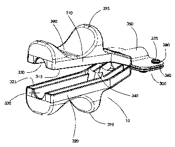
CATHETER GRIPPING DEVICE
Background of the Invention
Field of the invention
[0001] The present invention relates to a gripping device for gripping a
urinary
catheter within a closed pouch. Particularly, the invention relates to a
device that
allows the user of a urinary catheter contained within a sterile urinary
catheter pouch
to manually grip the urinary catheter as it is advanced out of the pouch for
use, with
minimal need for user dexterity or personal grip strength.
Background of the Invention
[0002] A wide variety of catheters are available for insertion into the body
for
introduction or withdrawal of fluids. Urinary catheters are flexible tubes
designed to
drain urine from the bladder by insertion into the urethra. They are packaged
in sterile
containers and can be lubricated for insertion prior to packaging or priot to
use.
Intermittent urinary catheters are designed to be inserted for each use and
are
commonly used by patients who are able to catheterize themselves. One type of
intermittent catheter comprises a urine catheter pouch, which also serves as
the
sterile package for the catheter. See, for example, U.S. patents 3,854,483 to
Powers,
5,226,530 to Golden, 6,004,305 to Hursman et al, 5,147,341 to Starke et al and
6,053,905 to Daignault et al. Another type of catheter is an intermittent
catheter
contained in a conduit pouch, whereby the pouch can be opened and used to
transfer urine to the toilet or a urine collection container.
[0003] Catheterization is accomplished by introducing the proximal tip of a
catheter into the urethra, and then "longitudinally collapsing and extending
the pouch
in an accordion-like manner until the tip reaches the bladder" as described in
US
Patents 6,602,224 to Kavanagh and 4,062,363 to Bonner. The portion of the
catheter
remaining within the pouch is gripped between the walls of the pouch advanced
out
of the pouch and into the urethra. During the pouch-extending phase, the
catheter is
1
CA 02579702 2007-02-27
held to resist a movement of the catheter back into the pouch by gripping the
catheter between the pouch walls. The operation requires two hands to
accomplish,
as well as dexterity to make sure that the catheter does not retract back into
the
pouch. It is a difficult, if not impossible, activity for a quadriplegic, high
paraplegic or
person with low grip strength to accomplish. Few, if any, products serve the
setf
catheterization market for these users.
[0004] Further, complications can make the process next to impossible, even
for those with great dexterity or strength. For example, the fluid pressure
from the
bladder or the weight from the urine may tend to pull the lubricated catheter
from the
urethra and back into the urinary catheter pouch. To prevent this from
occurring, the
user must continuously grip the catheter until voiding is completed. Catheters
are
normally heavily lubricated and have to be gripped between the walls of the
plastic
pouch. This can create a "slippery noodle" effect, which means that the grip
strength
and dexterity required to immobilize the catheter from retracting into the
pouch may
be so great that self-catheterization becomes impossible, even for someone
with
normal grip strength.
[0005] What is needed is a device to assist in the gripping of a urinary
catheter,
while it is in a urinary catheter pouch, for use by persons with limited
strength and
dexterity.
2
CA 02579702 2007-02-27
SUMMARY OF THE INVENTION
[0006] The present invention relates to a urinary catheter gripping device for
use with a urinary catheter located within a urinary catheter pouch. In one
aspect,
the urinary catheter pouch has a port defined in its exterior surface, whereby
the port
is in communication with the interior cavity of the urinary catheter pouch. In
this
aspect, the urinary catheter is substantially disposed therein the pouch and
is
configured to selectively pass therethrough the port. The gripping device can
be
positioned on the pouch at any convenient location that aids in the holding of
the
catheter.
[0007] The gripping device, in one aspect, comprises a gripper assembly with
a first gripper member and a second gripper member. In one aspect, the first
and
second gripper members define the catheter pathway to be configured such that
a
catheter may fit in the pathway, along with the pouch material, when the
catheter is
gripped through the pouch walls with the gripping device. The pathway is
further
designed to allow the catheter to move therethrough when the gripping device
is
being repositioned with respect to the catheter as the gripping device is
disengaged.
[0008] These and other objects of the present invention will be clear when
taken in view of the detailed specification and disclosure in conjunction with
the
appended figures.
DETAILED DESCRIPTION OF THE DRAWINGS
[0009] The accompanying drawings, which are incorporated in and constitute a
part of this specification, illustrate certain aspects of the instant
invention and
together with the description, serve to explain, without limitation, the
principles of the
invention. Like reference characters used therein indicate like parts
throughout the
several drawings.
3
CA 02579702 2007-02-27
[0010] Fig.1 is a top perspective view of one gripper member of the gripping
device according to the present invention.
[0011] Fig. 2 is a bottom perspective view of one gripper member of the
gripping device of Fig. 1.
[0012] Fig. 3 a top perspective view of the gripping device of Fig. 1.
[0013] Fig. 4 is a side perspective view of the gripping device of Fig. 1.
[0014] Fig. 5 is a cross-sectional view of the gripping device of Fig. 1,
showing
a urinary catheter within a urinary catheter pathway.
[0015] Fig. 6 is a perspective view of the gripping device of Fig. 1, mounted
on
a urinary catheter pouch.
[0016] Fig. 7 is a perspective view of an alternate embodiment of the gripping
device according to the present invention.
[0017] Fig. 8 is a cross-sectional view of the gripping device of Fig. 7,
showing
two pincher points.
[0018] Fig. 9 is an opened assembly view of an altemate embodiment of the
gripping device according to the present invention, where the first and second
gripper
members are permanently joined.
[0019] Fig. 10 is a perspective view of the gripping device of Fig. 9.
[0020] Fig. 11 is a frontal view of the gripping device of Fig. 7, showing
gripper
seals.
4
CA 02579702 2007-02-27
[0021] Fig. 12 is a perspective view of the gripping device of Fig. 11.
[0022] Fig. 13 is a perspective view of on gripper members of the gripping
device of Fig. 7, showing the gripper seals and a pincher point.
DETAILED DESRIPTION OF THE INVENTION
[0023] The present invention may be understood more readily by reference to
the following detailed description of the invention and the Examples included
therein
and to the Figures and their previous and following description.
[0024] Before the present systems, articles, devices, and/or methods are
disclosed and described, it is to be understood that this invention is not
limited to
specific systems, specific devices, or to particular methodology, as such may,
of
course, vary. It is also to be understood that the terminology used herein is
for the
purpose of describing particular embodiments only and is not intended to be
limiting.
[0025] The following description of the invention is provided as an enabling
teaching of the invention in its best, currently known embodiment. To this
end, those
skilled in the relevant art will recognize and appreciate that many changes
can be
made to the various aspects of the invention described herein, while still
obtaining
the beneficial results of the present invention. It will also be apparent that
some of
the desired benefits of the present invention can be obtained by selecting
some of
the features of the present invention without utilizing other features.
Accordingly,
those who work in the art will recognize that many modifications and
adaptations to
the present invention are possible and can even be desirable in certain
circumstances and are a part of the present invention. Thus, the following
description is provided as illustrative of the principles of the present
invention and not
in limitation thereof.
CA 02579702 2007-02-27
[0026] As used in the specification and the appended claims, the singular
forms "a," "an" and "the" include plural referents unless the context clearly
dictates
otherwise. Thus, for example, reference to "a gripping device" includes two or
more
such gripping devices, and the like.
[0027] Ranges can be expressed herein as from "about" one particular value,
and/or to "about" another particular value. When such a range is expressed,
another
embodiment includes from the one particular value and/or to the other
particular
value. Similarly, when values are expressed as approximations, by use of the
antecedent "about," it will be understood that the particular value forms
another
embodiment. It will be further understood that the endpoints of each of the
ranges
are significant both in relation to the other endpoint, and independently of
the other
endpoint. It is also understood that there are a number of values disclosed
herein,
and that each value is also herein disclosed as "about" that particular value
in
addition to the value itself. For example, if the value "10" is disclosed,
then "about
10" is also disclosed. It is also understood that when a value is disclosed
that "less
than or equal to" the value, "greater than or equal to the value" and possible
ranges
between values are also disclosed, as appropriately understood by the skilled
artisan.
For example, if the value "10" is disclosed the "less than or equal to 10"as
well as
"greater than or equal to 10" is also disclosed. It is also understood that
throughout
the application, data is provided in a number of different formats and that
this data
represents endpoints and starting points, and ranges for any combination of
the data
points. For example, if a particular data point "10" and a particular data
point 15 are
disclosed, it is understood that greater than, greater than or equal to, less
than, less
than or equal to, and equal to 10 and 15 are considered disclosed as well as
between 10 and 15. It is also understood that each unit between two particular
units
are also disclosed. For example, if 10 and 15 are disclosed, then 11, 12, 13,
and 14
are also disclosed.
6
CA 02579702 2007-02-27
[0028] "Optional" or "optionally" means that the subsequently described event
or circumstance may or may not occur, and that the description includes
instances
where said event or circumstance occurs and instances where it does not.
[0029] The present invention relates to a urlnary catheter gripping device 10
for use with a urinary catheter 100 located within a urinary catheter pouch
200. In
one aspect, the urinary catheter pouch 200 has a port 210 defined in its
exterior
surface 220, whereby the port 210 is in communication with the interior cavity
230 of
the urinary catheter pouch. In this aspect, the urinary catheter 100 is
substantially
disposed therein the pouch and is configured to selectively pass therethrough
the
port. As one skilled in the art can appreciate, the catheter may or may not be
lubricated.
[0030] The gripping device 10 can be positioned on the pouch at any
convenient location that aids in the holding of the catheter. In one
embodiment, the
user or health care worker obtains the gripping device separately from the
catheter
and positions and attaches the gripping device in a desired location on the
urine
catheter pouch for optimum use of the individual user. In other embodiments,
the
gripping device is pre-positioned and attached prior to use by the end user or
health
care worker. Normally, a location closer to the user would be preferred, but
positioning is well within the skill in the art.
[0031] The gripping device 10, in one aspect, comprises a gripper assembly
300 with a first gripper member 310 and a second gripper member 320. In
another
aspect, the first gripper member 310 comprises a first pinch face 315 and the
second
gripper member 320 comprises a second pinch face 325. The first and second
gripper members may be attached to each other such that they define a catheter
pathway 330. In one aspect, the first and second gripper members define the
catheter pathway 330 to be configured such that a catheter 100 may fit in the
pathway, along with the pouch material, when the catheter is gripped through
the
pouch walls with the gripping device The pathway is further designed to allow
the
7
CA 02579702 2007-02-27
catheter to move therethrough when the gripping device is being repositioned
with
respect to the catheter as the gripping device is disengaged. In one aspect,
the
pathway extends from the point of attachment of the gripping device to the
opposite
end of the gripping device 10. In another aspect, the pathway is essentially
half of a
channel on the pinch face side of each gripper member. The shape of the
pathway
can be tubular, rectangular, or a combination of shapes. However, regardless
of the
exact shape, it will define a bounded area that the catheter can move through.
In one
aspect, the catheter pathway 330 is tubular at each end and is a bounded area
in the
middle which is in the shape of the pinch face side of the gripper member.
[0032] Each gripper member may act as a lever arm. "Lever arm," as meant
herein, is a rigid or semi-rigid bar or beam that is free to pivot, bend, flex
or the like
around a fixed point or moment in order to take advantage of the mechanical
force
produced by the moment action. The two gripper members of the invention may be
positioned in opposing positions to produce an opposing gripping force from
both
sides of a catheter 100 to be gripped. When applying force to each gripper
member
in combination, the gripping device increases the amount of force being
applied to
the catheter, as compared with gripping the catheter directly through the
urinary
catheter pouch with fingers alone. Each gripper member can be, for example,
made
of a substantially rigid or semi-rigid material, such as a rigid polymer,
metal, wood,
laminated material, or the like. Some examples of suitable rigid polymers of
the
invention include polypropylene, polyethylene, polycarbonate, or the like.
Further,
rigidity or flexibility can be adjusted by the thickness of the material
selected, design
factors, such as cross beams, as well as other structural support means known
in the
art.
[0033] In yet another aspect, the gripper assembly 300 is configured to attach
to the exterior surface 220 of the urinary catheter pouch, such that the
catheter,
which is located within the interior cavity 230 of the urinary catheter pouch,
is
positioned substantially within the catheter pathway. As such, in one aspect,
at least
a portion of at least one of the first and second gripper members are
selectively
8
CA 02579702 2007-02-27
movable between a first position, in which the respective first and second
pinch faces
of the first and second gripper members do not engage the urinary catheter
(the
catheter is free to move relative to the catheter pathway), and a second
position, in
which at least a portion of the respective first and second pinch faces of the
first and
second gripper members engage a portion of the urinary catheter such that the
catheter is prevented from moving relative to the catheter pathway. In use,
the user
engages the gripping device to the catheter 100, advances a portion of the
catheter
therethrough a port in the urinary catheter pouch, disengages the gripping
device
from the catheter, repositions the gripper to another point along the
longitudinal
length of the catheter, and repeats the process until a sufficient length of
the catheter
has been advanced to achieve urine flow.
[0034] In one aspect of the invention for a urinary catheter gripping device,
the
first pinch face 315 of the first gripper member is positioned adjacent the
second
pinch face 325 of the second gripper member 320. In another aspect, the first
pinch
face of the first gripper member substantially faces the second pinch face of
the
second gripper member. In this aspect, the second pinch face of the second
gripper
member is configured to cooperate with the first pinch face of the first
gripper
member 310.
[0035] In one aspect, each pinch face comprises one or more pincher points
340. For example, and not meant to be limiting, the pincher points 340 may
comprise
a plurality of protrusions configured to grasp the urinary catheter 100 within
the
catheter pathway 330. In this aspect, when force is applied to each gripper
member,
most of the force is directed to the pincher points. By "pincher points" it is
meant
herein as a means for grasping, crimping or otherwise immobilizing or
preventing
longitudinal movement of a catheter positioned in the catheter pathway when
the
gripping device is engaged. In one aspect, the pincher points are designed
such that
they will not puncture the urinary catheter pouch 200 nor damage the catheter
during
use. In another aspect, the pincher points consist of one or more protrusions
of a
shape designed to function as described. One embodiment is a triangular shaped
9
CA 02579702 2007-02-27
pincher point, although a rectangular or other type pincher point is also
disclosed.
Likewise, the choice of one, two, or more pincher points 340 will depend on
the size
of the catheter, the material from which it is made, as well as a number of
other
physical factors known in the art. The pincher points can be on one gripper
member
or both gripper members. For ease in manufacturing, identical gripper members
can
be manufactured as suggested above, thus having opposing pincher points on
opposite sides of a catheter placed in the channel. In another embodiment, the
pincher points are staggered.
[0036] The length of each gripper member depends on several factors. In one
aspect, each gripper member is the same length. As one skilled in the art will
appreciate, the longer the lever, the greater the grip strength created.
However, the
longer the gripper members are, the further the arms stick out from the
urinary
catheter pouch surface when used, thus creating an obstruction. If grip
strength is too
great, the pincher points 340 can damage the urinary catheter pouch 200 or the
catheter 100 during use. The length of the gripper member will depend on the
size of
the catheter as well. One skilled in the art in view of this disclosure can
vary the
length of the gripper member and optimize the length for a given catheter and
urinary
catheter pouch combination. In one aspect, the length of the lever is from
about 1.25
cm to about 15 cm. In another aspect, the gripper member is straight. However,
in
yet another aspect, the gripper member has an angle bend from about 20 degrees
to
about 60 degrees.
[0037] In one aspect, the gripper members are positioned such that, in their
open relaxed state, they do not impede the movement of the catheter in the
catheter
pathway. Particularly, the pincher points should allow for the movement of the
catheter during distal or proximal movement. One way to achieve this, for
example, is
to ensure the levers are about 25-45 degrees relative to the surface of the
pouch 200
to achieve catheter clearance.
CA 02579702 2007-02-27
[0038] In yet another aspect of the invention, the first gripper member
comprises a first mount member 350 that is hingedly connected to the first
pinch face
315. In one aspect, the second gripper member 320 also comprises a second
mount
member 360 that is connected to the second pinch face 325. The second mount
member 360 may be hingedly connected to the second pinch face. The mount
members are configured to engage an outer portion of the urinary catheter
pouch to
mount the gripping device 10 thereto.
[0039] The mount members, as discussed herein, have a variety of means for
attaching the gripping device to the urinary catheter pouch. For instance, at
least
one male tab 370 may extend therefrom at least one of the respective first and
second mount members. The male tab 370 would be configured to be operatively
received within at least one female cavity 380 which would be defined therein
at least
one of the respective first and second mount members. In one aspect, each male
tab and each female cavity 380 form a snap-fit connection. In another aspect,
as the
mount members are attached to a portion of the urinary catheter pouch, the
exterior
surface of the urinary catheter pouch is interposed therebetween the connected
first
and second mount members such that first mount member is connected to the
front
face of the urinary catheter pouch and the second mount member 360 is
connected
to the back face of the urinary catheter pouch 200. This "snap-fit" method is
easy to
attach, but takes a great deal of force to disengage. In one aspect, there are
2 or
more corresponding male tabs and female cavities. In yet another aspect, the
female
cavities and male tabs are matching such that identical gripper members can be
used
for the first and second gripper members of the invention and when lined up on
opposite sides of the pouch their opposing male tabs 370 and female cavities
align.
In another aspect, the mount members are attached to the pouch by use of
cantilever
beam tabs and cavities, as seen in Fig. 7. The male tabs can also be designed
to
puncture the bag. Where snaps, rivets, or the like are used, which puncture
the
pouch, a pin or the like that is used can be swaged or heat staked to increase
locking
force. Where the bag is not punctured by the attachment mechanism, various
means
11
CA 02579702 2007-02-27
to seal the puncture from leakage can be used. For example, sealing washers or
0-
rings can be used to prevent leakage.
[0040] Each of the gripper members may also comprise a gripping tab 390. A
"gripping tab" as used herein is a surface texture treatment of the gripping
device that
allows a more secure place to grip with the fingers by increasing the friction
or
surface area of the surface in the area to be gripped. This can be
accomplished by
roughing the area, placing knobs, raised surface bumps, or the like, which
increase
surface area and make gripping by the fingers easier. It can also be an
indentation, a
valley, or a flat area that holds the fingers relatively stationary at the
desired location.
The gripping tab 390 can be constructed as either a universal hand style, or
be
angled to be used by either a right hand or left hand. It could also be
designed to be
gripped by the thumb and forefinger or the crook of the hand between the thumb
and
forefinger. The area to be gripped can be positioned toward the distal end of
each
gripper member in order to make the most use of the leverage produced by the
gripper member.
[0041] In one aspect, the first gripper member is equipped with a finger
placement guide 395, which is opposed to the first pinch face. The finger
placement
guide should help position the fingers on the gripping device properly and
further aid
in gripping the gripping device during use. Similarly, in one aspect, the
second
gripper member is equipped with a finger placement guide which is opposed to
the
second pinch face. In one aspect, the finger placement guides 395 consist of a
raised area of sufficient height to prevent substantial movement of the
fingers during
normal use of the gripping device.
[0042] Another embodiment of the invention relates to a method of preventing
movement of a urinary catheter 100 relative to a urinary catheter pouch by
using the
apparatuses as described herein. In one aspect, the method comprises the steps
of
a) providing a urinary catheter that is at least partially disposed in the
interior cavity of
a urinary catheter pouch; and b) selectively pressing opposed gripper members
12
CA 02579702 2007-02-27
toward each other to thereby force opposed portions of the urinary catheter to
frictionally engage the urinary catheter with sufficient force to selectively
prevent
movement of the urinary catheter relative to the catheter pathway 330. Once
the
gripper members are engaged with the urinary catheter, the catheter 100 may be
advance therethrough the port 210 in the urinary catheter pouch 200 for the
user to
perform necessary functions, such as, for example, insertion into the urethra.
[0043] Although several embodiments of the invention have been disclosed in
the foregoing specification, it is understood by those skilled in the art that
many
modifications and other embodiments of the invention will come to mind to
which the
invention pertains, having the benefit of the teaching presented in the
foregoing
description and associated drawings. It is thus understood that the invention
is not
limited to the specific embodiments disclosed herein above, and that many
modifications and other embodiments are intended to be included within the
scope of
the appended claims.
[0044] Moreover, although specific terms are employed herein, as well as in
the claims which follow, they are used only in a generic and descriptive
sense, and
not for the purposes of limiting the described invention, nor the claims which
follow.
13