Sélection de la langue

Search

Sommaire du brevet 2583899 

Énoncé de désistement de responsabilité concernant l'information provenant de tiers

Une partie des informations de ce site Web a été fournie par des sources externes. Le gouvernement du Canada n'assume aucune responsabilité concernant la précision, l'actualité ou la fiabilité des informations fournies par les sources externes. Les utilisateurs qui désirent employer cette information devraient consulter directement la source des informations. Le contenu fourni par les sources externes n'est pas assujetti aux exigences sur les langues officielles, la protection des renseignements personnels et l'accessibilité.

Disponibilité de l'Abrégé et des Revendications

L'apparition de différences dans le texte et l'image des Revendications et de l'Abrégé dépend du moment auquel le document est publié. Les textes des Revendications et de l'Abrégé sont affichés :

  • lorsque la demande peut être examinée par le public;
  • lorsque le brevet est émis (délivrance).
(12) Brevet: (11) CA 2583899
(54) Titre français: MICRO BLINDE POUR DISPOSITIF DE COMMUNICATION MOBILE
(54) Titre anglais: SHIELDED MICROPHONE FOR MOBILE COMMUNICATIONS DEVICE
Statut: Accordé et délivré
Données bibliographiques
(51) Classification internationale des brevets (CIB):
  • H05K 09/00 (2006.01)
  • H04R 01/00 (2006.01)
  • H04R 01/02 (2006.01)
(72) Inventeurs :
  • PHILLIPS, ROBERT W. (Canada)
(73) Titulaires :
  • RESEARCH IN MOTION LIMITED
(71) Demandeurs :
  • RESEARCH IN MOTION LIMITED (Canada)
(74) Agent: NORTON ROSE FULBRIGHT CANADA LLP/S.E.N.C.R.L., S.R.L.
(74) Co-agent:
(45) Délivré: 2011-03-08
(22) Date de dépôt: 2007-04-04
(41) Mise à la disponibilité du public: 2007-10-07
Requête d'examen: 2007-04-04
Licence disponible: S.O.
Cédé au domaine public: S.O.
(25) Langue des documents déposés: Anglais

Traité de coopération en matière de brevets (PCT): Non

(30) Données de priorité de la demande:
Numéro de la demande Pays / territoire Date
06112357.6 (Office Européen des Brevets (OEB)) 2006-04-07

Abrégés

Abrégé français

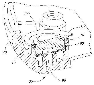
L'invention porte sur un micro blindé et sur le procédé de blindage connexe. Ce micro est destiné à servir dans un dispositif de communication mobile équipé d'une carte de circuits imprimés et d'un micro, notamment lorsque ledit dispositif est aussi muni d'une antenne montée tout près du micro. Le micro est logé dans un réceptacle offrant une protection électromagnétique (p. ex. une boîte de blindage) et muni d'un séparateur résilient (joint torique ou disque) monté sur le blindage. Le boîtier du dispositif est monté par dessus le séparateur et le blindage, alors que ce dernier est placé au dessus de la carte de circuits imprimés, le micro étant pris en sandwich entre le boîtier et la carte. En empilant ainsi les composants, le séparateur appuie sur le blindage de façon à pousser celui-ci contre la carte de circuits pour la mettre à la masse, le micro étant aussi branché à la carte de circuits. Ce dernier se trouve donc coincé entre la carte de circuits et le blindage qui l'isole de l'énergie électromagnétique diffusée par l'antenne avoisinante. La résilience du séparateur laisse un jeu suffisant pour l'empilage des composants.


Abrégé anglais


A shielded microphone, and method for shielding a microphone, are provided for
use in a communications device having a circuit board and a microphone,
especially where the device also has an antenna in close proximity to the
microphone. The microphone is provided in an electromagnetic shield (e.g.
formed as a shielding can) and a resilient separator (e.g. o-ring or disk) is
provided over the shield. The device housing is stacked over the separator and
shield, while the latter are stacked over the circuit board so that the
separator and
shield, with microphone there under, are sandwiched between the housing and
the circuit board. By this sandwiching the separator is loaded onto the shield
to
drive the shield directly against the circuit board to make an electrical
ground
connection therewith, the microphone also being electrically connected to the
printed circuit board. The microphone is thereby enclosed between the circuit
board and the shield, such that the shield shields the microphone against
electromagnetic energy radiated by the proximate antenna. The resilience of
the
separator accommodates the variation in the stacking of the components.

Revendications

Note : Les revendications sont présentées dans la langue officielle dans laquelle elles ont été soumises.


8
Claims:
1. A shielded microphone assembly comprising a microphone and a
conductive, electromagnetic shield, for use in a communications device having
a
circuit board and a housing, and in use being proximate to an antenna,
characterized by a resilient separator over said electromagnetic shield,
wherein
said conductive, electromagnetic shield is over said microphone and said
assembly is configured to co-operate with said housing and said circuit board
to
electrically connect each of said microphone and said electromagnetic shield
to
said circuit board upon loading said housing onto said separator and said
electromagnetic shield onto said circuit board, thereby enclosing said
microphone between said circuit board and said electromagnetic shield and
grounding said electromagnetic shield.
2. A shielded microphone assembly according to claim 1, wherein said
electromagnetic shield is formed as a shielding can having a lip, said
shielding
can electrically connecting to said circuit board by means of said lip.
3. A shielded microphone assembly according to claim 2, wherein said
separator is a resilient o-ring surrounding an outside perimeter of said
shielding can over said lip.
4. A shielded microphone assembly according to claim 1, wherein said
electromagnetic shield is formed as a shielding can and said separator is a
resilient disk positioned over a ceiling of said shielding can, said ceiling
configured for positioning adjacent said housing upon said loading of said
housing.
5. A shielded microphone assembly according to claim 4, wherein said disk
is aligned over said shielding can, upon said loading of said housing, by
means
of a channel formed in said housing.

9
6. A shielded microphone assembly according to any one of claims 1-5,
wherein said separator comprises an electrically insulating material.
7. A shielded microphone assembly according to any one of claims 1-6,
wherein said circuit board is a printed circuit board.
8. A shielded microphone assembly according to any one of claims 1-7,
wherein said electromagnetic shield comprises an outlet for communication of
sound waves to said microphone.
9. A shielded microphone assembly according to claim 4 or claim 5, wherein
said disk comprises a central aperture for communication of sound waves to
said
microphone.
10. A mobile communications device comprising an antenna and a shielded
microphone assembly in accordance with any one of claims 1 to 9.
11. A method of shielding a microphone in a communications device
having a circuit board and a housing, said device being used with an antenna
either as part of said device or in proximity to said device, the method
comprising
shielding said microphone with a conductive, electromagnetic shield over said
microphone and characterized by the steps of:
providing a resilient separator over said electromagnetic shield; and
sandwiching said shielded microphone and separator between said
housing and said circuit board,
whereby said shielded microphone and separator are configured to co-
operate with said housing and said circuit board to electrically connect each
of
said microphone and said electromagnetic shield to said circuit board, said
electromagnetic shield being thereby grounded, said sandwiching producing a
loading of said housing onto said separator and said electromagnetic shield
onto
said circuit board, thereby enclosing said microphone between said circuit
board

and said electromagnetic shield.
12. A method according to claim 11, whereby said electromagnetic shield is
formed as a shielding can having a lip, said shielding can electrically
connecting
to said circuit board by means of said lip.
13. A method according to claim 12, whereby said separator is a resilient o-
ring provided to surround an outside perimeter of said shielding can.
14. A method according to claim 11, whereby said electromagnetic shield is
formed as a shielding can and said separator is a resilient disk provided over
a
ceiling of said shielding can, said ceiling being positioned adjacent said
housing
upon said loading of said housing.
15. A method according to any one of claims 11 to 14, whereby said separator
comprises an electrically insulating material.
16. A method according to any one of claims 11 to 15, whereby said
electromagnetic shield comprises an outlet for communication of sound waves to
said microphone.
17. A method according to any one of claims 11 to 16, whereby said
microphone is fixed to said circuit board and said circuit board is a printed
circuit
board.
18. A method according to any one of claims 11 to 17, whereby said
microphone is held against said circuit board by said electromagnetic shield.

Description

Note : Les descriptions sont présentées dans la langue officielle dans laquelle elles ont été soumises.


CA 02583899 2007-04-04
1
SHIELDED MICROPHONE FOR MOBILE COMMUNICATIONS DEVICE
Mobile, handheld communications devices typically contain a miniature
microphone such as an electret condenser microphone. In such devices, the
microphone is typically held against a printed circuit board and electrically
connects to the circuit board via a pair of small coil springs. Such devices
also
typically have an antenna in close proximity to the microphone with the
attendant
possibility that the microphone can undesirably pick up, as noise,
electromagnetic
energy radiated by the antenna. In the case of mobile telephones, this
undesirable noise is sometimes referred to in the industry as "GSM buzz". To
shield the microphone against such noise pick-up, a grounded shield
(hereinafter
alternatively referred to as an "electromagnetic shield") is typically used to
surround or enclose the microphone so as to isolate the microphone,
electromagnetically, from such radiation.
In the typical mass production of handheld, mobile communications devices, a
number of parts are stacked together and enclosed in a housing. The stack of
parts must, when fully assembled, occupy the space defined by the housing of
the
device. The variability in the size of the parts in the stack and their proper
placement during assembly requires that tolerances be factored into the design
of
the stack of parts. The pressure between the various parts in the stack
ultimately
depends upon the aggregate size of the parts made to occupy the well-defined
space. As excess pressure between the parts may cause undesirable strain and
damage thereto, resilient parts capable of absorbing the stack pressure are
typically included. Furthermore, in assembling such devices, it is important
that
the method of mounting the microphone and the electromagnetic shield onto the
circuit board be able to accommodate the tolerances of assembly while, at the
same time, ensure that an effective electrical connection is made, as
required,
between the circuit board and each of the microphone and electromagnetic
shield.
The problem of providing for both the tolerances of assembly and electrical
connection between the electromagnetic shield and circuit board have been
addressed by placing a conductive gasket between the shield and the circuit

CA 02583899 2007-04-04
2
board, with such gasket being sufficiently compliant to absorb the stack
pressure
and required assembly tolerances and the its conductivity providing an
electrical
connection between the shield and the circuit board. However, those gaskets
are
relatively expensive and their placement is critical and, thus, poses greater
difficult
during assembly of the device, since they function as an intermediary
component
between the shield and the circuit board to establish the electrical
connection
between them.
There is, therefore, a need, in a communications device having a microphone
and
an antenna in close proximity, for a shield assembly which both protects the
microphone against energy radiated by the antenna and is able to economically
achieve the necessary electrical connections that withstand manufacturing
tolerances.
BRIEF DESCRIPTION OF THE DRAWINGS
An understanding of exemplary embodiments of the invention will be obtained
from the following description, with reference to the following drawings in
which
like reference numerals refer to like components throughout:
FIG. 1 shows a cross-sectional, pictorial perspective view of an exemplary
shielded microphone assembly in accordance with one such embodiment (of
which the circuit board has been omitted to better show the remaining
components);
FIG. 2 shows a cross-sectional, pictorial plan view of the embodiment of FIG.
1 in
which an o-ring-type separator is used;
FIG. 3 shows a cross-sectional, pictorial, plan view of another exemplary
embodiment of the microphone assembly in which a gasket-type separator is
used; and,

CA 02583899 2007-04-04
3
FIG. 4 shows a flowchart illustrating steps of a method in accordance with
another
aspect of the invention for assembling a shielded microphone for mounting onto
a
circuit board.
DESCRIPTION OF PREFERRED EMBODIMENTS
In accordance with an aspect of the invention, a shielded microphone assembly
is
preferably provided for use in a communications device having a circuit board
and
a housing and having an antenna or used proximate to an antenna. The
microphone is placed inside a conductive, electromagnetic shield (e.g. a
shielding
can) and a separator (e.g. an o-ring-type) is placed over the shield, forming
an
assembly configured to co-operate with the housing and the circuit board to
electrically connect each of the microphone and the electromagnetic shield to
the
circuit board. The device housing can then be stacked over the assembly,
namely, over the shield to load the separator onto the shield and drive the
shield
directly against the circuit board, whereby the shield becomes grounded
through
an electrical connection with the circuit board. As a result, the microphone
is
enclosed between the circuit board and the electromagnetic shield, and is
shielded against electromagnetic energy radiated by the nearby antenna. Since
the separator is resilient it accommodates the variation in the stack of
parts. The
electromagnetic shield, when formed as a shielding can, may have a lip whereby
the shielding can electrically connects to the circuit board by means of the
lip.
The separator (preferably an electrical insulator), when formed as a resilient
o-
ring, preferably surrounds an outside perimeter of the shielding can over the
lip.
Or, the separator, when formed as a resilient disk, is preferably positioned
over a
ceiling of the shielding can, where the ceiling is configured to be positioned
adjacent the housing upon the loading of the housing. The electromagnetic
shield
may include an outlet for communication of sound waves to the microphone.
A further aspect of the invention preferably provides a mobile communications
device comprising an antenna and a shielded microphone assembly according to
the foregoing.

CA 02583899 2007-04-04
4
A still further aspect of the invention preferably provides a method of
shielding a
microphone in such a communications device whereby the microphone is
shielded with a conductive, electromagnetic shield; a resilient separator is
provided over the electromagnetic shield; and, the shielded microphone and
separator are sandwiched between the housing and the circuit board. The
shielded microphone and separator are configured to co-operate with the
housing
and the circuit board to electrically connect each of the microphone and the
electromagnetic shield to the circuit board, thereby grounding the
electromagnetic
shield. The sandwiching produces a loading of the housing onto the separator
and the electromagnetic shield onto the circuit board, thereby enclosing the
microphone between the circuit board and the electromagnetic shield.
The foregoing disadvantages of the known shielded microphone assemblies can
be overcome by using a shielded microphone as described herein and illustrated
by FIG.'s 1 - 4. As shown for the embodiment illustrated by Fig.'s 1 and 2,
the
shielded microphone assembly 10 can be used in any suitable communications
device 20 having a circuit board 30 (see Fig. 2), which may be a printed
circuit
board, a housing 40 and, in a mobile communications device, an antenna (not
shown). The shielded microphone assembly 10 has an electromagnetic shield in
the form of a shielding can 50, a microphone 60 and a separator 70. The
shielding can 50 is composed of a conductive material and is grounded through
an electrical connection with an electrical ground contact of the circuit
board 30.
The shielding can 50 and the circuit board 30, when in contact, define an
enclosure 80. The microphone 60 is contained within the enclosure 80 and when
installed in a communications device is electrically connected with the
circuit
board 30. The shielding can 50 and the microphone 60 may be any suitable
shape such that the microphone 60 fits within the enclosure; accordingly, the
cross-sectional shape of the shielding can 50 may be circular, square,
hexagonal
or any other suitable shape which co-operates with the shape of the microphone
and circuit board. The microphone 60 may be held against the circuit board 30
by
the shielding can 50; alternatively, the microphone 60 may be soldered or
otherwise affixed to the circuit board 30.

CA 02583899 2007-04-04
The shielding can 50 includes an outlet 90 or other means for communicating
sound waves into the shielding can 50 and, thence, to the microphone 60. The
separator 70, which is made of a resilient material and may also be insulating
(e.g. rubber), is positioned between the shielding can 50 and the housing 40.
In
5 this manner, the shielding can 50 shields the enclosed microphone 60 from
electromagnetic energy, including electromagnetic energy from a proximate
antenna, while the separator 70, being resilient, is springy and able to
rebound
from, and absorb, pressure between the housing 40 and the shielding can 50.
In the exemplary embodiment of FIG.'s 1 and 2, the separator 70 is an o-ring-
type
separator positioned over the shielding can 50 and apart from the circuit
board 30,
so as to surround the outside perimeter of the shielding can 50. The shielding
can
50 of this embodiment includes a lip 100 over which the separator 70 is
positioned
such that, when installed in a communications device by stacking these
components with the housing 40 positioned there over and the circuit board 30
positioned there under, the lip 100 of the shielding can 50 is pressed into
electrical
contact with the circuit board 30. By this stacking, the separator 70 is
sandwiched
between the housing 40 and the lip 100, and the lip 100 is sandwiched between
the separator 70 and the circuit board 30.
Alternatively, as shown in FIG. 3, the separator 70 may be a resilient disk
positioned over a shielding can 50 which does not include such a lip. In this
embodiment, the ceiling (top) 55 of the shielding can 50 parallel to the
housing 40
is sandwiched between the disk separator 70 and the circuit board 30. As shown
for this embodiment, the disk separator 70 is aligned over the shielding can
50 by
means of an appropriately sized channel 110 formed in the housing 40. Further,
the disk separator 70 may include a central aperture 57, as shown, aligned in
the
stack with the counterpart outlet 90 of the ceiling of the shielding can 50
for
communication of sound waves to the microphone 60.
The challenges associated with the known methods of assembling a shielded
microphone, as discussed above, are overcome by using the method described
herein and illustrated by the flowchart of FIG. 4. The method 120 can be used
for

CA 02583899 2007-04-04
6
the production of any suitable communications device having a circuit board,
which may be a printed circuit board, a housing and, for mobiles devices, an
antenna. The method 120 is used for assembling a shielded microphone 10 and
mounting it onto a circuit board 30, wherein the shielded microphone assembly
includes a shielding can 50 and a microphone 60. As described above, the
shielding can 50 includes means for communicating sound waves into the
shielding can 50 to the microphone 60.
The shielding can 50 and the microphone 60 are mounted together, the
microphone being placed within the shielding can, and positioned 130 on the
circuit board 30 so that both the microphone and shielding are in electrical
contact
with the circuit board 30. A resilient separator 70 is positioned 140 over the
shielding can 50. The housing 40 is stacked over and pressed onto 150 the
separator 70 so as to load the separator 70, sandwiching it between the
housing
40 and the shielding can 50. In turn, the shielding can 50 is pressed against
the
circuit board 30, whereby the shielded microphone assembly becomes mounted
on the circuit board 30. The resilience of the separator 70 enables it to
absorb
(tolerate) the load placed on it by this stacking of the housing 40 onto the
shielding can 50 and circuit board 30 there under.
Alternatively, as illustrated in Fig. 4 by step 170 shown in dotted outline to
indicate
that it replaces the foregoing step 130 for this alternative, the microphone
60 of
the shielded microphone assembly may first be mounted onto the circuit board
30
(e.g. by soldering), followed by mounting of the shielding can 50 onto the
circuit
board 30 so as to cover the microphone 60.
As compared to the solutions known heretofore, the solutions described herein
facilitate the manufacturing of such devices while at the same time reducing
the
overall cost of parts.
With the foregoing exemplary embodiments having been disclosed, it will be
apparent to those skilled in the art that various changes and modifications
can be
made to appropriately suit the needs and objectives of another application and
still

CA 02583899 2007-04-04
7
achieve the advantages of the invention; all such changes and modifications
are
intended to fall within the scope of the invention as defined by the claims
that
follow.
Note: This patent disclosure and document contains material which is subject
to
copyright protection. The copyright owner has no objection to the facsimile
reproduction of any one of the patent disclosure or patent document, as it
appears
in the Patent Office patent file or records, but otherwise reserves all
copyright
rights whatsoever.

Dessin représentatif
Une figure unique qui représente un dessin illustrant l'invention.
États administratifs

2024-08-01 : Dans le cadre de la transition vers les Brevets de nouvelle génération (BNG), la base de données sur les brevets canadiens (BDBC) contient désormais un Historique d'événement plus détaillé, qui reproduit le Journal des événements de notre nouvelle solution interne.

Veuillez noter que les événements débutant par « Inactive : » se réfèrent à des événements qui ne sont plus utilisés dans notre nouvelle solution interne.

Pour une meilleure compréhension de l'état de la demande ou brevet qui figure sur cette page, la rubrique Mise en garde , et les descriptions de Brevet , Historique d'événement , Taxes périodiques et Historique des paiements devraient être consultées.

Historique d'événement

Description Date
Lettre envoyée 2024-04-04
Représentant commun nommé 2019-10-30
Accordé par délivrance 2011-03-08
Inactive : Page couverture publiée 2011-03-07
Inactive : Taxe finale reçue 2010-12-16
Préoctroi 2010-12-16
Un avis d'acceptation est envoyé 2010-07-16
Inactive : Lettre officielle 2010-07-16
Lettre envoyée 2010-07-16
Un avis d'acceptation est envoyé 2010-07-16
Inactive : Approuvée aux fins d'acceptation (AFA) 2010-06-18
Lettre envoyée 2010-05-10
Exigences relatives à la révocation de la nomination d'un agent - jugée conforme 2010-04-26
Inactive : Lettre officielle 2010-04-26
Exigences relatives à la nomination d'un agent - jugée conforme 2010-04-26
Requête en rétablissement reçue 2010-04-09
Modification reçue - modification volontaire 2010-04-09
Exigences de rétablissement - réputé conforme pour tous les motifs d'abandon 2010-04-09
Demande visant la nomination d'un agent 2010-04-07
Demande visant la révocation de la nomination d'un agent 2010-04-07
Inactive : Abandon. - Aucune rép dem par.30(2) Règles 2009-09-18
Modification reçue - modification volontaire 2009-09-18
Inactive : Dem. de l'examinateur par.30(2) Règles 2009-03-18
Inactive : Dem. de l'examinateur art.29 Règles 2009-03-18
Inactive : Page couverture publiée 2007-10-07
Demande publiée (accessible au public) 2007-10-07
Inactive : CIB en 1re position 2007-06-28
Inactive : CIB attribuée 2007-06-28
Inactive : CIB attribuée 2007-06-27
Demande reçue - nationale ordinaire 2007-05-03
Lettre envoyée 2007-05-03
Inactive : Certificat de dépôt - RE (Anglais) 2007-05-03
Exigences pour une requête d'examen - jugée conforme 2007-04-04
Toutes les exigences pour l'examen - jugée conforme 2007-04-04

Historique d'abandonnement

Date d'abandonnement Raison Date de rétablissement
2010-04-09

Taxes périodiques

Le dernier paiement a été reçu le 2010-04-06

Avis : Si le paiement en totalité n'a pas été reçu au plus tard à la date indiquée, une taxe supplémentaire peut être imposée, soit une des taxes suivantes :

  • taxe de rétablissement ;
  • taxe pour paiement en souffrance ; ou
  • taxe additionnelle pour le renversement d'une péremption réputée.

Les taxes sur les brevets sont ajustées au 1er janvier de chaque année. Les montants ci-dessus sont les montants actuels s'ils sont reçus au plus tard le 31 décembre de l'année en cours.
Veuillez vous référer à la page web des taxes sur les brevets de l'OPIC pour voir tous les montants actuels des taxes.

Titulaires au dossier

Les titulaires actuels et antérieures au dossier sont affichés en ordre alphabétique.

Titulaires actuels au dossier
RESEARCH IN MOTION LIMITED
Titulaires antérieures au dossier
ROBERT W. PHILLIPS
Les propriétaires antérieurs qui ne figurent pas dans la liste des « Propriétaires au dossier » apparaîtront dans d'autres documents au dossier.
Documents

Pour visionner les fichiers sélectionnés, entrer le code reCAPTCHA :


Pour visualiser une image, cliquer sur un lien dans la colonne description du document (Temporairement non-disponible). Pour télécharger l'image (les images), cliquer l'une ou plusieurs cases à cocher dans la première colonne et ensuite cliquer sur le bouton "Télécharger sélection en format PDF (archive Zip)" ou le bouton "Télécharger sélection (en un fichier PDF fusionné)".

Liste des documents de brevet publiés et non publiés sur la BDBC .

Si vous avez des difficultés à accéder au contenu, veuillez communiquer avec le Centre de services à la clientèle au 1-866-997-1936, ou envoyer un courriel au Centre de service à la clientèle de l'OPIC.

({010=Tous les documents, 020=Au moment du dépôt, 030=Au moment de la mise à la disponibilité du public, 040=À la délivrance, 050=Examen, 060=Correspondance reçue, 070=Divers, 080=Correspondance envoyée, 090=Paiement})


Description du
Document 
Date
(aaaa-mm-jj) 
Nombre de pages   Taille de l'image (Ko) 
Description 2007-04-03 7 289
Revendications 2007-04-03 3 104
Abrégé 2007-04-03 1 26
Dessins 2007-04-03 4 62
Dessin représentatif 2007-09-16 1 14
Revendications 2010-04-08 3 112
Abrégé 2010-12-15 1 26
Avis du commissaire - Non-paiement de la taxe pour le maintien en état des droits conférés par un brevet 2024-05-15 1 556
Accusé de réception de la requête d'examen 2007-05-02 1 176
Courtoisie - Certificat d'enregistrement (document(s) connexe(s)) 2007-05-02 1 105
Certificat de dépôt (anglais) 2007-05-02 1 158
Avis de retablissement 2010-05-09 1 171
Courtoisie - Lettre d'abandon (R30(2)) 2010-04-25 1 164
Avis du commissaire - Demande jugée acceptable 2010-07-15 1 164
Correspondance 2010-04-06 2 98
Correspondance 2010-04-25 1 18
Correspondance 2010-04-25 1 15
Correspondance 2010-12-15 2 69