Note : Les descriptions sont présentées dans la langue officielle dans laquelle elles ont été soumises.
CA 02597364 2007-08-15
1
"Synthetic grass turf and related manufacturing
method"
***
The present invention relates to synthetic (or
"artificial") grass coverings.
Synthetic-grass coverings have been used for quite
some time now, in particular to provide areas of
greenery for urban decoration and similar amenities,
for areas for bordering swimming-pools, and, in
general, for replacing natural-grass cover in all those
conditions where the laying and maintenance of a
natural-grass cover may prove critical. The use of
synthetic-grass coverings has received new impulse in
recent times in order to provide coverings for sports
facilities, for example, soccer pitches. The
corresponding literature is extremely extensive, as is
witnessed, at a patent level, by documents such as: US-
A-3 731 923, US-A-4 337 283, US-A-5 958 527, US-A-
5 961 389, US-A-5 976 645, JP-B-32 53 204, JP-A-
10037122, DE-A-44 44 030, EP-A-0 377 925, and EP-A-
1 158 099.
In particular, from the document mentioned last,
which is owned by the owner of the present applicant, a
synthetic-grass structure is known, which comprises a
sheet-like substrate with a plurality of filiform
formations extending from the substrate for simulating
the grassy sward of natural turf and a particulate
filling material, or infill, dispersed between the
filiform formations so as to keep the filiform
formations themselves in a substantially upright
condition. Specifically, the above synthetic-grass
covering is characterized in that the particulate
filling material (infill) is constituted by a
CA 02597364 2014-02-07
2
substantially homogeneous mass of a granular material
chosen in the group constituted by polyolefin-based
materials and by vinyl polymer-based materials.
Further advantageous developments of the above
solution are described in the documents EP-A-1 319 753,
EP-A-1 375 750, EP-A-1 371 779, as well as EP-A-1 486 613,
and EP1803841, all of said documents being filed in the
name of the present applicant.
In the course of the last few years, as regards
application to the construction of grass coverings for
sports facilities, the activity of innovation has been
aimed chiefly at the characteristics and modalities of
distribution of the filling material or infill.
As a whole, less attention has instead been paid to
the characteristics of the yarn used for making said
filiform formations. In this connection, reference may be
made, for example, to EP-A-0 259 940, which describes,
instead, the possibility of using, in a synthetic-grass
covering, a yarn obtained with the co-extrusion of
polymeric materials of different composition, in
particular with different coefficients of friction.
A solution widely used for making the aforesaid
filiform formations envisages resorting to a yarn having
a base of plastic material, such as polyethylene. The
material in question is initially laminated so as to form
a sheet of the thickness of, for example, 200 - 300
micron. The sheet is then subjected to a cutting
operation, which divides the sheet into a large number of
strips of small width (for example, 10 - 20 mm). The
cutting operation is usually followed by one or more
operations of longitudinal stretching, as well as by
possible operations of fibrillation.
CA 02597364 2007-08-15
3
An alternative technique ("single-
thread"
technique) envisages, instead, that a material
originating as a single thread from a threading die is
subjected to a process of longitudinal stretching.
Whatever the technique adopted for making it, the
yarn thus obtained is wound onto reels. The reels in
question are then used for supplying workstations that
form the basic structure of a synthetic-grass covering
of the type described previously, i.e., with the
filiform formations that extend from a sheetlike
substrate. Said workstations operate typically with
known techniques resembling techniques of tufting or
the like.
In particular, these techniques aim at
"implanting" in the sheetlike substrate (which is
continuous or substantially continuous, for example,
because it is provided with draining holes) yarn
formations having a general U-shaped configuration.
Each formation basically constitutes a sort of tuft
with a looped part that passes underneath the
substrate, and two lateral branches that extend
vertically above the substrate simulating blades of
grass. In the case of the single thread, instead, the
tuft is constituted by four, six or else eight strands
or "blades", according to the thickness and/or width of
the blade itself.
The operation of fibrillation (performed either
before or after implantation in the substrate)
basically has the purpose of "giving more body" to the
yarn and hence the tuft formed therewith. The tuft is
in fact usually constituted by one or more threads that
tend to widen out so that the single tuft of synthetic
grass appears more dense and hence more similar to a
tuft of natural grass. In the case of bladelike
CA 02597364 2007-08-15
4
elements, the blades subjected to fibrillation each
split into a number of strands.
Albeit as a whole satisfactory, these traditional
techniques leave room for further improvements as
regards various aspects.
An important aspect relates to the anchorage of
the filiform formations to the sheetlike substrate.
A widely used technique envisages applying, on the
underside of the substrate (i.e., the one that is to be
oriented downwards when the synthetic-grass covering is
laid), an aqueous dispersion of latex, such as SBR
latex. The solution in question is dried and the latex,
so to speak, plugs or "stops" the openings for passage
of the filiform formations through the sheetlike
substrate. The action of anchorage thus achieved
cannot, however, be said to be satisfactory in so far
as the filiform formations can be torn away with
relative ease.
Other solutions (such as for example, the ones
described in US-B-6 338 885 or US-B-6 723 412) envisage
the application, once again on the underside of the
substrate, of strips of adhesive tape or adhesive
material that are to anchor the looped parts of the U-
shaped configurations referred to previously more
firmly.
An important drawback of this technique derives
from the fact that the aforesaid strips form a ribbing
on the underside of the filiform substrate, which no
longer rests completely on the laying foundation and
ends up assuming marked directional characteristics as
regards resistance to mechanical stresses.
The aspect mentioned last assumes particular
importance in view of the fact that the sheetlike
substrate of the synthetic-grass covering should be
able to perform an effective action of dimensional
CA 02597364 2007-08-15
stablization of the synthetic-grass covering, an action
that is not in general performed satisfactorily by
sheet layers of a traditional type, for example, with a
base of laminas of polyester and/or polypropylene.
5 The main object then of the present invention is
to improve existing synthetic-grass coverings in regard
both to the aspects referred to previously, i.e.,
anchorage of the filiform formations to the substrate
and the action of stablization of the synthetic-grass
covering by the sheetlike substrate.
According to the present invention, this object is
achieved thanks to a synthetic-grass covering having
the characteristics referred to specifically in the
ensuing claims. The invention also relates to a
corresponding method.
The claims form an integral part of the technical
disclosure provided herein in relation to the
invention.
The invention will now be described, purely by
way of non-limiting example with reference to the
figures of the annexed plate of drawings, in which:
- Figures 1 to 4 illustrate successive steps of a
possible method of construction of a synthetic-grass
covering of the type described herein;
- Figure 5 illustrates a possible variant
embodiment of the synthetic-grass covering illustrated
in Figures 1 to 4; and
- Figure 6 is a schematic illustration of a
synthetic-grass covering of the type described herein
integrated with an infill of granular material, in the
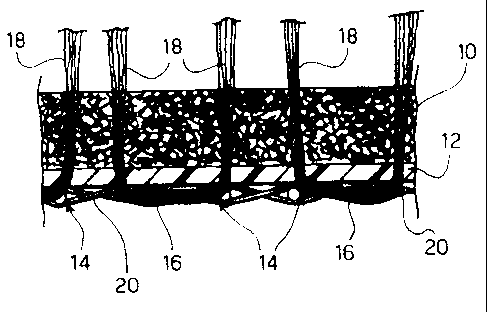
typical position of laying and final use.
In Figure 1 of the annexed plate of drawings, the
reference number 10 designates a pad having a thickness
substantially equal to 3 mm and a weight per unit area
CA 02597364 2007-08-15
6
substantially equal to 300 g/m2, constituted with a
base of polyester or PET.
In the framework of the invention, there may in
any case advantageously be used thicknesses typically
of between by 1.5 mm (weight per
unit area:
150 g/m2) and 4 mm (weight per unit area: 400 g/m2)
and/or any polyolefin-based material.
The term "pad" is herein meant to indicate a sheet
material obtained starting from threads, yarns or
fibres associated together in such a way as to:
- bestow upon the layer of material 10 qualities
of mechanical resistance to tensile forces, such as to
cause the pad 10 not to tear in the normal conditions
of use referred to in what follows; and
- cause there to be in any case present, between
the threads, yarns or fibres, empty spaces such as to
enable a firm anchorage of the pad 10 to a further
layer of coating 12 (and, possibly a mesh 20),
described in greater detail in what follows.
For example, the pad 10 can be made in the form
of:
- a simple-woven fabric (so as to present a weft
and a warp),
- a knitted fabric,
- a non-woven fabric or a felt, possibly
stabilized with a weft quilting.
Of course, the embodiments described above can
also be combined together, envisaging, for example, the
formation of the pad 10 in the form of a non-woven
fabric subsequently quilted/matelasse with a warp-and-
weft pattern.
When the above characteristic does not already
derive intrinsically from the constitutive material (as
in the case of polyester or PET), the pad 10 can be
CA 02597364 2007-08-15
7
treated with known agents so as to be rendered
hydrophobic.
Figure 2 illustrates coupling of the pad 10 to the
layer 12, as mentioned previously.
The layer 12 is constituted by a thermoplastic
(hence heat-meltable) material, typically by a
polyolefin-based material, such as, for example,
polyethylene.
Coupling of the layer 12 to the pad 10 can be
obtained with various techniques in themselves known.
For example, the layer of material 12 can be
coupled to the pad 10 via hot-pressing. Alternatively,
the layer 12 can be spread on the pad 10. Alternative
techniques comprise spraying of the layer of the
material 12 in the liquid or molten state with
subsequent consolidation, and connection obtained via
the application of ultrasound.
The connection is obtained preferably in a
continuous way over the entire facing surfaces of the
pad 10 of the layer 12. Less preferred solutions
envisage that the connection is made only on portions
of the facing surfaces (for example, with a knitted or
sewn pattern) and/or with a connection of a mechanical
type, for example, via quilting or the like.
In an embodiment that is particularly preferred
(but in itself not imperative), it is envisaged that,
as represented schematically in Figure 5, up against
the layer 12 there is set (preferably coupled to the
layer 12 applied on the pad 10, operating in a single
passage) a stabilizing mesh 20, constituted, for
example, by a mesh once again made of thermoplastic and
hence heat-meltable material, and preferably of a
polyester with a thermoset and stabilized meshwork,
with weight per unit area of between 30 g/m2 and
150 g/m2 (preferably substantially equal to 80 g/m2).
CA 02597364 2007-08-15
8
The combined laminated material (pad 10 plus layer
12 and, if present, mesh 20) thus obtained is then used
as laminar substrate for the construction of a
synthetic-grass covering according to the modalities
(in themselves known) referred to schematically in
Figure 3.
The combined laminated material 10, 12 (and,
possibly, 20) is fed into equipment (not illustrated,
but of a type in itself widely known in the sector of
manufacture of synthetic-grass coverings) substantially
resembling a tufting machine.
The equipment in question implants in the
sheetlike substrate 10, 12 (and, possibly, 20) yarn
formations 14 having a general U-shaped configuration.
Each formation basically constitutes a sort of tuft
with a looped part 16 that passes underneath the
substrate 10, 12 and two branches 18 that extend
vertically above the substrate 10, 12 simulating blades
of grass.
In subsequent steps of the method of manufacture
of the synthetic-grass covering (steps not illustrated
herein, also because in themselves they are not
important for the purposes of understanding and
implementing the invention), the aforesaid two branches
18 can be subjected to further treatments for example,
fibrillation, curling, etc. designed to cause the
threads that make them up to reproduce in an even more
faithful way the appearance of the grassy sward of
natural turf.
The operation of implantation of the filiform
formations 14 is obtained in such a way that the looped
parts 16 are in contact with the layer 12 (and the mesh
20, if present), whilst the formations 18 protrude with
respect to the general plane of the substrate 10, 12 on
the side where the pad 10 is set.
CA 02597364 2007-08-15
9
The structure of synthetic-grass covering thus
obtained is then subjected to the action of a heating
element H (e.g., a plate or heated roller, which
operates preferably in contact) according to the
modalities schematically represented in Figure 4, the
purpose being to produce localized melting - with
consequent mutual welding - of the looped parts 16 and
of the areoles of the layer 12 (and of the mesh 20, if
present) in an area corresponding to which the looped
parts 16 extend.
The welding is obtained thanks to the fact that
both the material of the filiform formations 14 (and
hence of the looped parts 16) and the material of the
layer 12 (and of the mesh 20, if present) are made of
thermoplastic material, hence heat-meltable and heat-
weldable. For this very reason, in a particularly
preferred embodiment of the invention, the material of
the layer 12 is chosen so that it is the same as - or
at least substantially similar to - the material
constituting the filiform formations 14.
As has already been said, polyethylene constitutes
a preferential choice from this standpoint. The choice
of polyethylene enables in fact a homogeneous and
intimate welding to be obtained, applying on the
underside of the structure represented in Figure 3
temperatures in the range of 110 C to 200 C, according
to the rate/time of application, hence without any risk
of inducing negative phenomena either in the pad 10 or
in the parts of the filiform formations 14 designated
by 18, which are to simulate the grassy sward of
natural turf.
The connection by heat-welding is immediately
appreciable in the sense that the filiform formations
14 are connected in a definitive and very firm way to
the laminar substrate or sheetlike substrate
CA 02597364 2007-08-15
constituted by the pad 10 and by the layer 12 (and, if
present, by the mesh 20).
At the same time, the ensemble formed by the pad
10 and by the layer 12 (and by the mesh 20, if present)
5 provides the sheetlike substrate of the synthetic-grass
covering with excellent qualities of dimensional
stability and of resistance to tensile forces, to
deformation and tearing. These qualities are manifested
in a practically uniform way in all directions, thus
10 preventing said substrate (and hence the synthetic-
grass covering as a whole) from presenting undesirable
characteristics of directionality of behaviour.
The fact that the layer 10 presents the
characteristics of a pad of a certain thickness has the
beneficial effect of giving "body" to the synthetic-
grass covering also in the case where the latter is not
subsequently filled with a granular infill.
The characteristics of hydrophobicity of the pad
10 moreover mean that the synthetic-grass covering
presents excellent qualities of draining of rainwater,
thus preventing the formation of puddles or drenched
areas that could lead to stagnation.
As schematically illustrated in Figure 6, the
synthetic-grass covering described previously can
advantageously be integrated with "seeding" of a
filling material or "infill" 22 constituted by a
granular material, for example, a polyolefin-based one
(said term comprising of course also the so-called
"thermoplastic elastomers").
In an embodiment of the invention that at the
moment is particularly preferred, the aforesaid filling
material 22 is of the type described in EP-A-1 158 099.
Of course, without prejudice to the principle of
the invention, the details of construction and the
embodiments may widely vary with respect to what is
CA 02597364 2007-08-15
11
described and illustrated herein, without thereby
departing from the scope of the invention as defined by
the annexed claims.